

Page 1
http://www.BDTIC.com/ATMEL
AVR1502: Xplain Training - Direct Memory
Access Controller
Prerequisites
• Required knowledge
AVR1500: Xplain Training - XMEGA
• Software prerequisites
Atmel® AVR® Studio® 4.18 or later
WinAVR/GCC 20100110 or later
• Hardware prerequisites
JTAGICE mkII
Xplain evaluation board
• Estimated completion time:
2 hours
1 Introduction
This application note covers the basic features of the Atmel XMEGA Direct Memory
Access Controller (DMAC). The goal for this training is to getting started with
simple memory transfers almost without using CPU time, and reading and writing
to peripherals with hardly any CPU intervention.
™
Basics
8-bit
Microcontrollers
Application Note
There are four DMA channels that have individual source, destination, triggers and
block sizes. The DMA Controller can move data from one memory area to another,
between memories and peripherals and between peripherals.
Rev. 8310A-AVR-06/10
Page 2
2 Setting up the DMA Controller
http://www.BDTIC.com/ATMEL
The Atmel XMEGA Direct Memory Access Controller (DMAC) is a highly flexible fourchannel DMA Controller capable of transferring data between memories and
peripherals with minimal CPU intervention. While the CPU spends time in low-power
sleep modes or performs other tasks, the XMEGA DMAC offloads the CPU by taking
care of mere data copying from one area to another. The following sub-chapters are
meant to complement the understanding when doing the tasks in this training.
2.1 DMA Transaction
A complete DMA read and write operation between memories and/or peripherals is
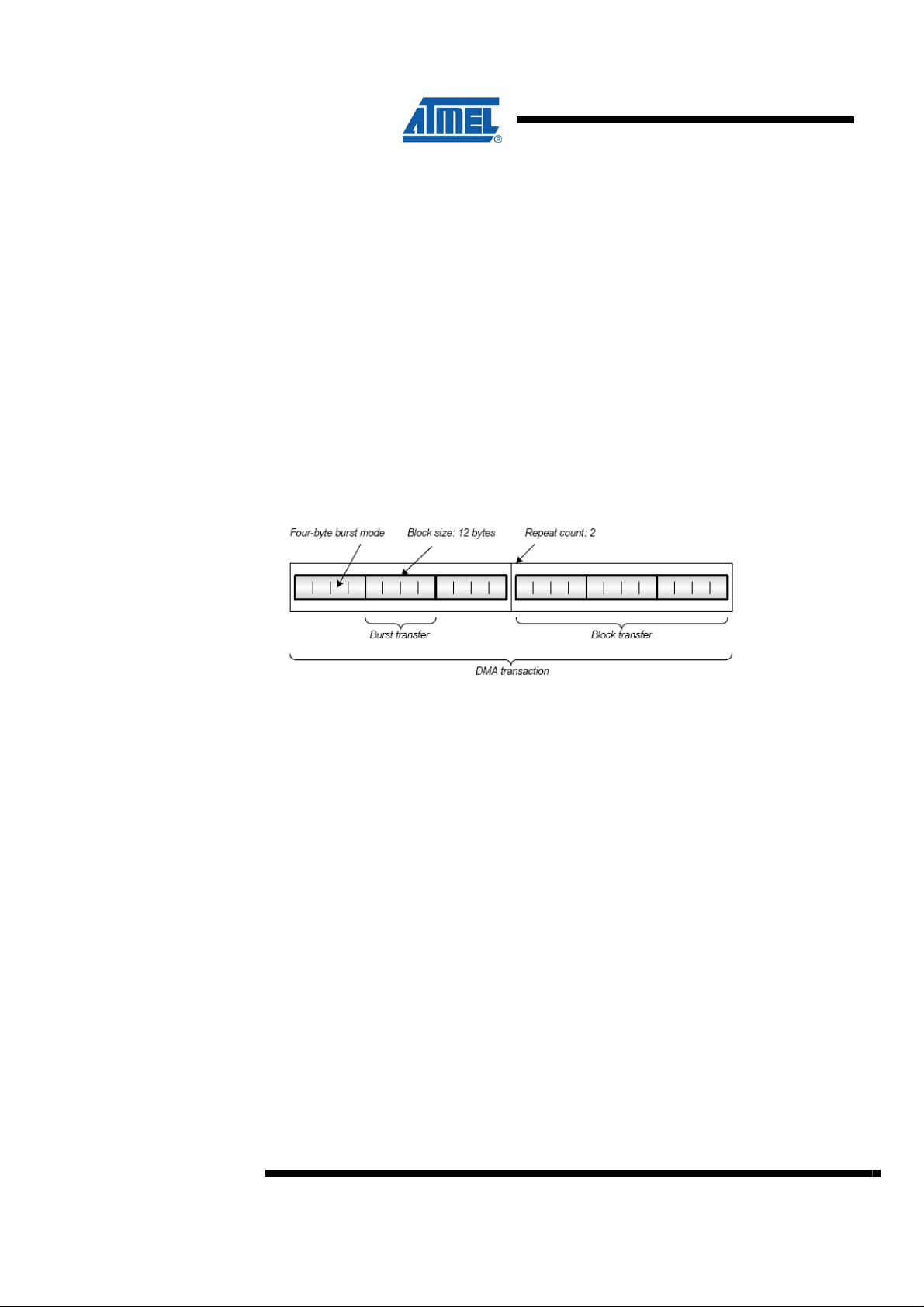
called a DMA transaction. A transaction is done in data blocks and the size of the
transaction (number of bytes to transfer) is selectable from software and controlled by
the block size and repeat counter settings. Each block transfer is divided into smaller
bursts, see Figure 2-1.
Figure 2-1. DMA Transaction
2.2 Addressing
When a DMA channel requests a data transfer, the bus arbiter will wait until the AVR
core is not using the data bus and permit the DMA Controller to transfer data.
Transfers are done in bursts of 1, 2, 4 or 8 bytes. Addressing can be static,
incremental or decremental. Automatic reload of source and/or destination address
can be done after each burst transfer, block transfer, when transfer is complete, or
disabled. DMA transfers can be triggered by application software, peripherals and
events.
The size of the block transfer is set by the Block Transfer Count Register, and can be
anything from 1 byte to 64 Kbytes. A repeat counter can be enabled to set a number
of repeated block transfers before a transaction is complete. The repeat is from 1 to
255 and unlimited repeat count can be achieved by setting the repeat count to zero.
A bus arbiter controls when the DMA controller and the AVR core can use the bus.
The core always has priority, so as long as the core request access to the bus, any
pending burst transfer must wait. The core requests bus access when it executes an
instruction that write or read data to SRAM, IO memory, EEPROM and the External
Bus Interface.
If the source or destination is SRAM, the user will most likely want to increment or
decrement the address pointer. Therefore, it is possible to set the DMAC source /
destination in incremental or decremental mode.
2
AVR1502
8310A-AVR-06/10
Page 3
http://www.BDTIC.com/ATMEL
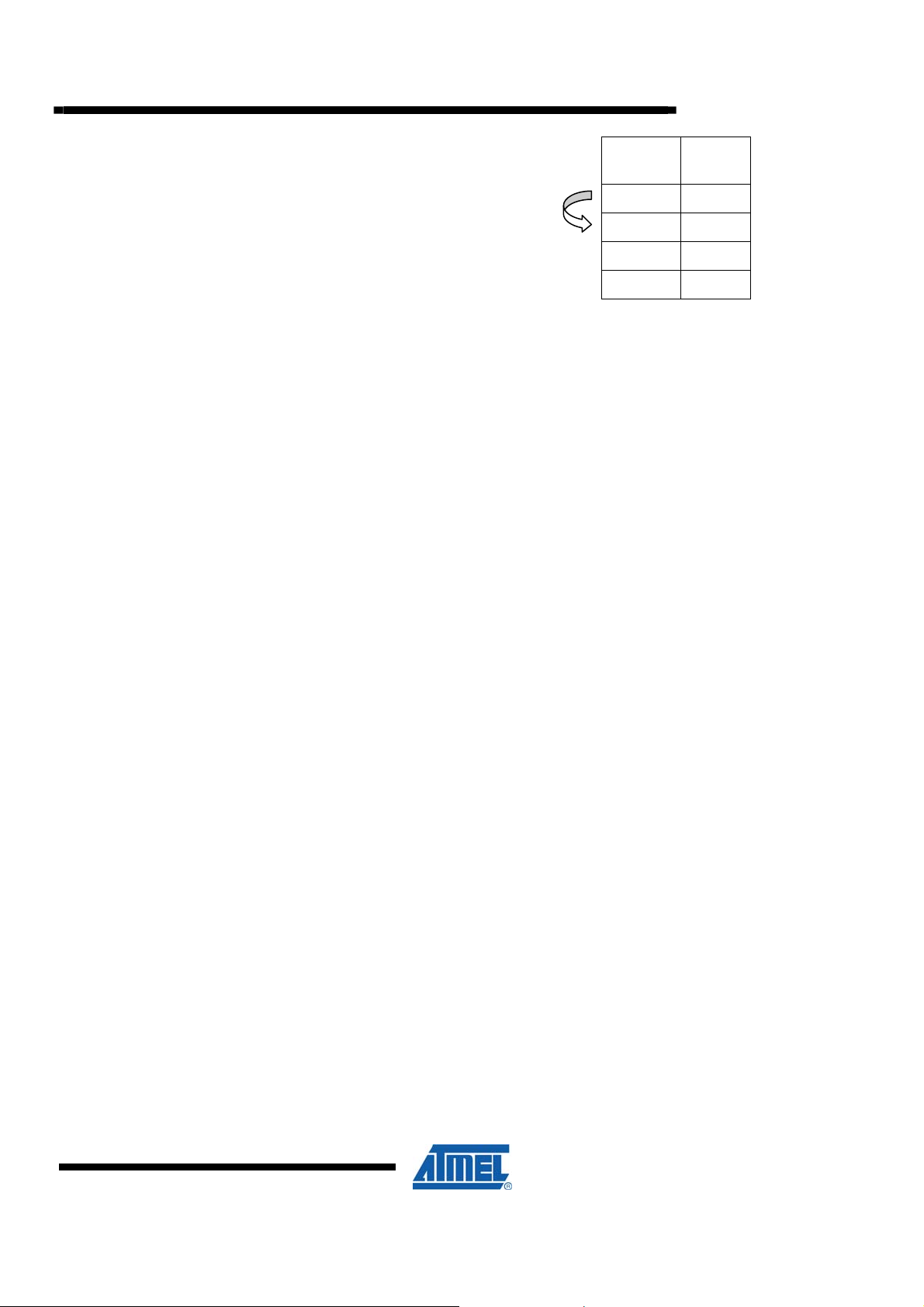
SRAM
Address
The DMAC will increment the
address pointer automatically in
incremental mode
In incremental mode, the DMAC will start at the source address. After the first byte
has been sent, the next byte will be read from the previous address plus one.
In decremental mode, it is opposite, where the DMAC will start at a given source
address and proceed with the previous addresses.
The original source and destination addresses are stored by the DMA controller, so
that the source and destination addresses can be individually configured to be
reloaded at the following points:
• End of each burst transfer
• End of each block transfer
• End of transaction
• Never reload
When using the DMAC with a peripheral, such as the SPI, the data register is fixed,
and it is important that the addressing mode is static.
0x2066 34
0x2067 76
0x2068 13
0x2069 113
Value
AVR1502
2.3 Transfer Triggers
2.4 Interrupts
The main purpose of the DMA triggers is to synchronize the peripherals with the
transfer rate. For instance, when using the USART and transferring at 9600 baud, the
DMA should not be triggered more often than the transfer complete flag is set.
DMA transfers can only be started when a DMA transfer request is detected. A
transfer request can be triggered from software, from an external trigger source
(peripheral) or from an event. There are dedicated source trigger selections for each
DMA channel. The available trigger sources may vary from one device to another,
depending on the modules or peripherals that exist in the device (see the XMEGA
manual for different transfer triggers).
The DMA Controller can generate interrupts when an error is detected on a DMA
channel or when a transaction is complete for a DMA channel. Each DMA channel
has a separate interrupt vector, and there are different interrupt flags for error and
transaction complete. If repeat is not enabled the transaction complete flag is set at
the end of the Block Transfer. If unlimited repeat is enabled, the transaction complete
flag is also set at the end of each Block Transfer.
8310A-AVR-06/10
3
Page 4

3 Overview
http://www.BDTIC.com/ATMEL
4 Task 1: Memory copy
Here is a short overview of the tasks in this training:
Task 1: Memory Copy
This task shows how to copy blocks of memory from one location to another without
CPU intervention. The task is divided in two parts.
1. The first part will show how to copy memory in SRAM with the DMAC
2. The second part will show how to set up an interrupt to indicate that the transfer is
done
Task 2: Interrupt mode
This task shows how to implement a simple recorder that records a ten second
sequence of switch presses and plays them back on the LEDs. The recording and
playback process is performed without CPU intervention.
DMA controllers are perfect for copying large chunks of memory from one location to
another. This task will demonstrate the block memory copy routine from the driver file.
It will also show how to set up the PMIC to get interrupt when the transfer is done.
The goal for this task is that you know how to:
• Use the driver code to set up the DMAC and start memory copy operations
• Set up the PMIC to trigger an interrupt when the transfer is done
4.1 Memory Copy: Polling approach
1. Open the project file MemoryCopy.aps in Atmel AVR Studio, and see the file
task1.c
2. Build the project (press F7) and start debugging (click on Play)
3. Locate the
both of them (“Add watch…” in right-click menu), see Figure 4-1
memoryBlockA and memoryBlockB definitions and add data watches for
4
AVR1502
8310A-AVR-06/10
Page 5

Figure 4-1. Locate memory blocks at top of task1.c
http://www.BDTIC.com/ATMEL
AVR1502
4. In main(), right-click on the call to
click menu, see Figure 4-2
5. Expand
contents. Are they equal? See Figure 4-3
Figure 4-2. Run to cursor
Figure 4-3. Compare memoryBlockA and memoryBlockB
memoryBlockA and memoryBlockB in the watch window and look into their
MemCopy and select ”Run to Cursor” in the right-
6. Step Over (F10) the call to
and
8310A-AVR-06/10
MemCopy and look onto the contents of memoryBlockA
memoryBlockB again. Are they equal now?
5
Page 6

7. Reset execution (Shift-F5) and run to MemCopy again. This time step into (press
http://www.BDTIC.com/ATMEL
F11) to access the function. Further, step into
driver configures the DMAC for you. You may want to refer to the introduction
chapter in order to answer these questions:
a) Is the memory copy set up as static, incrementing or decrementing? Why
is it set up this way?
b) Could another DMA channel have been used?
c) The software trigger source is used as default for this between memories
transfer. Why do you think this is convenient when copying from SRAM to
SRAM?
d) What is the burst length? Why do you think it is configurable?
4.2 Memory Copy: Interrupt approach
1. Add a break-point to the start of test two, as shown in Figure 4-4. And press F5 to
run
Figure 4-4. Add break point here
DMA_SetupBlock to see how the
2. If the previous test went fine (no errors in the transfer), then we are ready for the
next test. Single-step (press F10) some steps and notice that an interrupt is set up
to trigger when the next DMA transaction has completed
3. Look at the function
is no call to
The function DMA_ReturnStatus_blocking is polling until the DMA transfer has
finished. When using an interrupt instead to indicate that the transfer has finished, the
CPU will be free to do other operations.
4. At the bottom of task1.c, add a break-point in the interrupt service routine
ISR(DMA_CH0_vect), as shown in Figure 4-5. Press F5 to run
DMA_ReturnStatus_non_blocking
AsyncMemCopy. Notice that, in comparison with MemCopy, there
6
AVR1502
8310A-AVR-06/10
Page 7

5 Task 2: Recorder
http://www.BDTIC.com/ATMEL
Figure 4-5. Wait for interrupt
5. Run to completion (press F5) and break execution (Ctrl+F5) after a while. Verify
that the transfer went well by comparing
An application, for which the DMAC is really useful, is to copy data between memory
and peripherals such as ADCs and DACs. This task shows how to implement a
simple recorder that samples the switches for a period of time, stores it in a SRAM
buffer, and then plays the data back on the LEDs over and over again. The exact
same principle would be used if you should record sound with an ADC and play it
back on a DAC.
memoryBlockA and memoryBlockB
AVR1502
The goal for this task is that you know how to:
• Configure the DMAC to copy data from peripheral to SRAM
• Configure the DMAC to copy data from SRAM to peripheral
• Use a timer tick as a trigger source for DMA data transfers
1. Open the project file
and have a look at
2. Build the project (press F7), start debugging (click on Play), and run code (press
F5) to use the recorder:
a) The LEDs flash once
b) Press any switch
c) The LEDs flashes again
d) You have approximately 10 seconds to hammer at the switches while the
DMAC records the switch states
e) The LEDs flashes again
f) Press any switch
g) The LEDs flashes again
h) The DMAC will play back the switch recording on the LEDs until a switch is
pressed
i) The procedure starts over
3. Try changing the SAMPLE_COUNT definition or the sample rate. Recompile, run,
and see what happens. See Figure 5-1
DMA_Recorder.aps in the task2 folder in Atmel AVR Studio
task2.c
8310A-AVR-06/10
7
Page 8

Figure 5-1. Try changing SAMPLE_COUNT
http://www.BDTIC.com/ATMEL
4. Try to walk through the code to understand what happens. You may refer to the
introduction chapter when answering theses questions:
a) In the
b) In the
c) What would happen if you set the DMAC up with software trigger source, in
d) For the Read-channel, why are the source address fixed and the destination
e) Could the burst-length have been different, such as 4 or 8?
SetupReadChannel, what is the source and what is the destination?
SetupWriteChannel, what is the source and what is the destination?
this case?
address incremental?
8
AVR1502
8310A-AVR-06/10
Page 9

6 Summary
http://www.BDTIC.com/ATMEL
7 Resources
• Memory copy; DMAC from SRAM to SRAM
• Using interrupt source to indicate end of transfer
• Recording switch presses using DMAC. This application recorded the port pin
input states and saved the information in SRAM. The information that was saved
in SRAM was then set out to the LEDs. A timer overflow was used as a trigger
source
• Atmel XMEGA Manual and Datasheets.
o http://www.atmel.com/xmega
• Atmel AVR Studio with help files
o http://www.atmel.com/products/AVR/
• WINAVR GCC compiler
o http://winavr.sourceforge.net/
• Atmel IAR Embedded Workbench
o http://www.iar.com/
®
compiler
AVR1502
8 Atmel Technical Support Center
Atmel has several support channels available:
• Web portal: http://support.atmel.no/
• Email: avr@atmel.com
• Email: avr32@atmel.com
Please register on the web portal to gain access to the following services:
• Access to a rich FAQ database
• Easy submission of technical support requests
• History of all your past support requests
• Register to receive Atmel microcontrollers’ newsletters
• Get information about available trainings and training material
All Atmel microcontrollers
All AVR products
All 32-bit AVR products
8310A-AVR-06/10
9
Page 10

http://www.BDTIC.com/ATMEL
Disclaimer
Headquarters International
Atmel Corporation
2325 Orchard Parkway
San Jose, CA 95131
USA
Tel: 1(408) 441-0311
Fax: 1(408) 487-2600
Atmel Asia
Unit 1-5 & 16, 19/F
BEA Tower, Millennium City 5
418 Kwun Tong Road
Kwun Tong, Kowloon
Hong Kong
Tel: (852) 2245-6100
Fax: (852) 2722-1369
Atmel Europe
Le Krebs
8, Rue Jean-Pierre Timbaud
BP 309
78054 Saint-Quentin-enYvelines Cedex
France
Tel: (33) 1-30-60-70-00
Fax: (33) 1-30-60-71-11
Atmel Japan
9F, Tonetsu Shinkawa Bldg.
1-24-8 Shinkawa
Chuo-ku, Tokyo 104-0033
Japan
Tel: (81) 3-3523-3551
Fax: (81) 3-3523-7581
Product Contact
Web Site
www.atmel.com
Disclaimer: The information in this document is provided in connection with Atmel products. No license, express or implied, by estoppel or otherwise, to any
intellectual property right is granted by this document or in connection with the sale of Atmel products. EXCEPT AS SET FORTH IN ATMEL’S TERMS AND
CONDITIONS OF SALE LOCATED ON ATMEL’S WEB SITE, ATMEL ASSUMES NO LIABILITY WHATSOEVER AND DISCLAIMS ANY EXPRESS, IMPLIED
OR STATUTORY WARRANTY RELATING TO ITS PRODUCTS INCLUDING, BUT NOT LIMITED TO, THE IMPLIED WARRANTY OF MERCHANTABILITY,
FITNESS FOR A PARTICULAR PURPOSE, OR NON-INFRINGEMENT. IN NO EVENT SHALL ATMEL BE LIABLE FOR ANY DIRECT, INDIRECT,
CONSEQUENTIAL, PUNITIVE, SPECIAL OR INCIDENTAL DAMAGES (INCLUDING, WITHOUT LIMITATION, DAMAGES FOR LOSS OF PROFITS,
BUSINESS INTERRUPTION, OR LOSS OF INFORMATION) ARISING OUT OF THE USE OR INABILITY TO USE THIS DOCUMENT, EVEN IF ATMEL HAS
BEEN ADVISED OF THE POSSIBILITY OF SUCH DAMAGES. Atmel makes no representations or warranties with respect to the accuracy or completeness of the
contents of this document and reserves the right to make changes to specifications and product descriptions at any time without notice. Atmel does not make any
commitment to update the information contained herein. Unless specifically provided otherwise, Atmel products are not suitable for, and shall not be used in,
automotive applications. Atmel’s products are not intended, authorized, or warranted for use as components in applications intended to support or sustain life.
© 2010 Atmel Corporation. All rights reserved. Atmel®, Atmel logo and combinations thereof, AVR®, AVR® logo AVR Studio® and others, are
the registered trademarks, XMEGA
be trademarks of others.
Literature Request
www.atmel.com/literature
TM
and others are trademarks of Atmel Corporation or its subsidiaries. Other terms and product names may
Technical Support
avr@atmel.com
Sales Contact
www.atmel.com/contacts
8310A-AVR-06/10
 Loading...