

Page 1

http://www.BDTIC.com/ATMEL
AVR1501: Xplain training – XMEGA
Timer/Counter
Prerequisites
• Required knowledge
Completed AVR1500: XMEGA
• Software prerequisites
Atmel® AVR® Studio® 4.18 SP2 or later
WinAVR/GCC 20100110 or later
• Hardware prerequisites
- Xplain evaluation board
- JTAGICE mkII
• Estimated completion time:
- 2 hours
1 Introduction
Atmel XMEGA has a set of high-end and very flexible 16-bit Timer/Counters (TC).
Their basic capabilities include accurate program execution timing, frequency and
waveform generation, event management, and time measurement of digital
signals.
™
Basics training
8-bit
Microcontrollers
Application Note
In this hand-on we will learn more about the XMEGA timers, PWM generation, High
resolution Extension and Advanced Waveform extension.
Rev. 8309A-AVR-06/10
Page 2

2 Overview
http://www.BDTIC.com/ATMEL
Atmel XMEGA has a set of high-end and very flexible 16-bit Timer/Counters (TC).
Their basic capabilities include accurate program execution timing, frequency and
waveform generation, event management, and time measurement of digital signals.
The Timer/Counter consists of a Counter (COUNT) and a set of Compare and
Capture (CC) channels. It has direction (DIR) control and period (PER) settings that
can be used for timing.
The Hi-Resolution Extension (Hi-Res) and Advanced Waveform Extension (AWeX)
can be used together with a Timer/Counter to ease implementation of more advanced
and specialized frequency and waveform generation features.
Here is a short overview of the tasks in this training:
Task 1: Starting the Timer/Counter
In the first task you will be guided through initial setup to start the Timer/Counter,
including the prescaler and period settings.
Task 2: Compare Match
In this task you will learn how to use the Capture/Compare (CCx) registers for
compare checking.
Task 3: Waveform Generation
The CC channels and compare match can be used for waveform generation output
on the I/O pins, and in this task you will learn how to configure this.
Task 4: AWeX and Pattern Generation
The Timer/Counter extensions can be used to enable more specialized features. In
this task we will look at the Common Waveform and Pattern Generation modes.
Good luck!
2
AVR1501
8309A-AVR-06/10
Page 3

3 Task 1: Starting the Timer/Counter
http://www.BDTIC.com/ATMEL
The Timer/Counter needs a clock source to run. The available clock sources are the
(pre-scaled) Peripheral Clock and the Event System. In this task we will only use the
Peripheral Clock, but setting up the TC to use the Event System is equally easy.
The goal for this task is that you know how to:
• Start the Timer/Counter using the prescaler (CLKSEL bits) in the CTRLA register
• Use the PER register, to set how far the counter should count
TASK:
1. Locate the Atmel XMEGA-TimerCounter folder, find the Task 1 folder and open the
StartingTheTimer.aps project file in Atmel AVR Studio
2. Look through the code and ensure that you understand how things are set up
3. Build the project; ensure that there are no errors
4. Start the debugging session
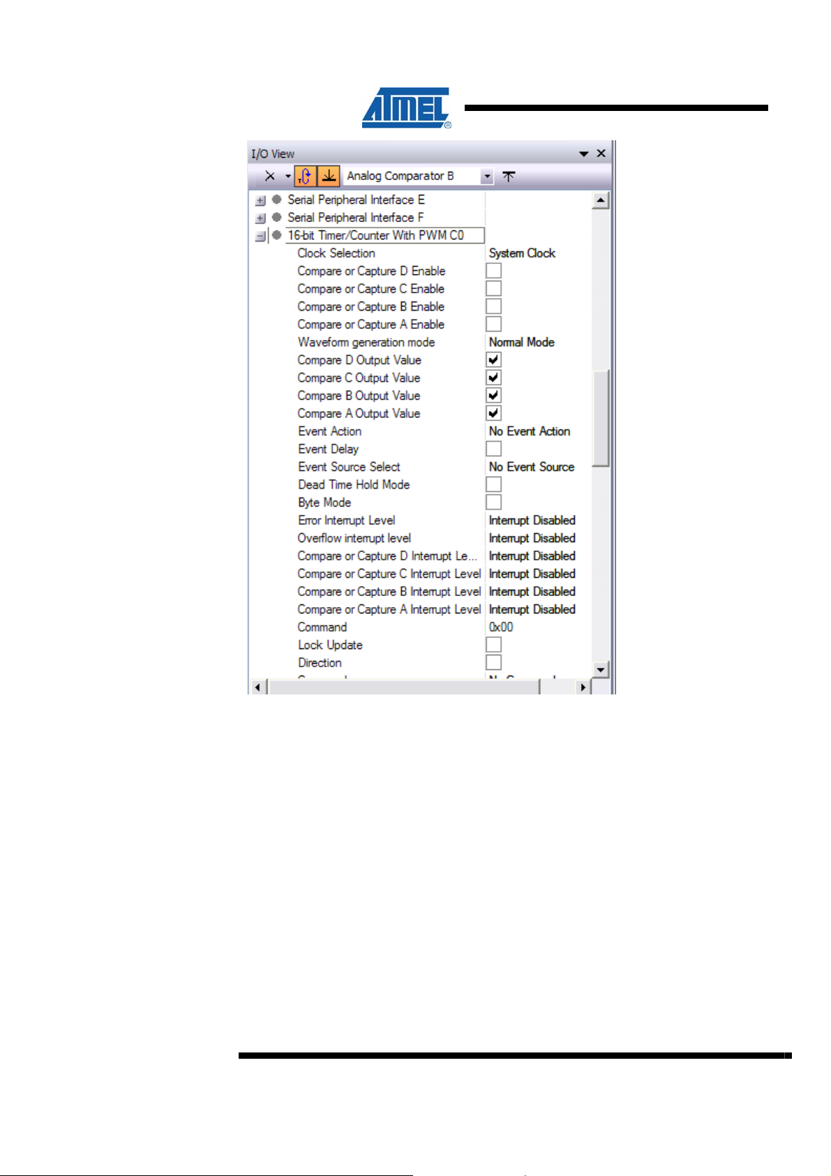
5. In the I/O-view locate the 16-bit Timer/Counter with PWM C0, and expand it, so
you can see the settings change as you start debugging
AVR1501
8309A-AVR-06/10
3
Page 4
http://www.BDTIC.com/ATMEL
4
6. Single step through the code until you reach the while (1) statement
7. The TCC0 is now running in Normal Mode with no pre-scaling, and you can see
the TCC0 setup details by using the IO view
8. Continue to single step and you will see that the Count (CNT) value is changing
and that the OVVIF in INTFLAGS is set when the Count (CNT) register reach 0x30
and wraps around. The LED will toggle
9. Run the code (F5). You will notice that both LED0 and LED1 will be on. This is
because the code runs too fast for you to see the LEDs toggle
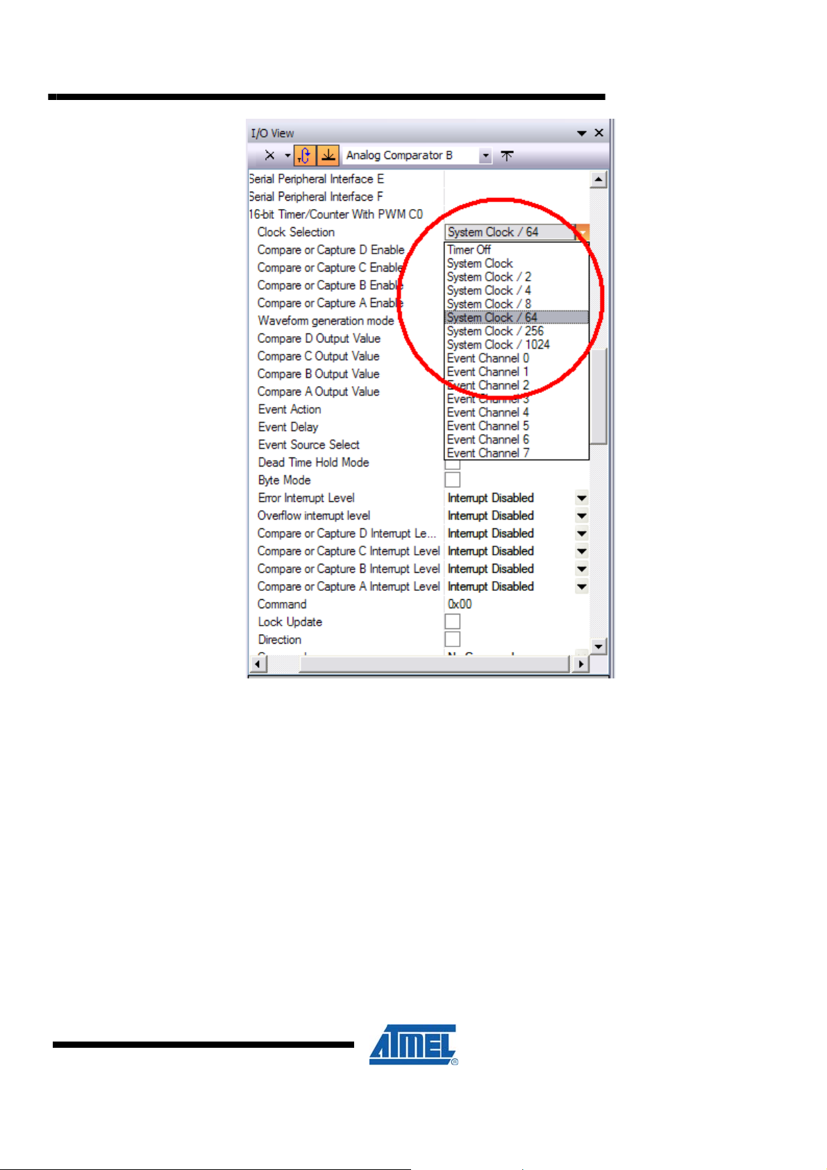
10. Break the execution (Ctrl+F5). Change the Clock Selection so that the TC runs
from the Peripheral Clock divided by 64 using the I/O view in Atmel AVR Studio
AVR1501
8309A-AVR-06/10
Page 5
http://www.BDTIC.com/ATMEL
AVR1501
8309A-AVR-06/10
11. Change the Period (PER) register to a higher value so you can see that the LED
toggles when you run the code
12. A higher PER setting gives a longer period for the timer, hence the LED will toggle
with a slower frequency
5
Page 6

http://www.BDTIC.com/ATMEL
6
AVR1501
8309A-AVR-06/10
Page 7

4 Task 2: Compare Match in Normal Mode
http://www.BDTIC.com/ATMEL
Task1 showed how to set up a basic timer function. Task2 will show how to use the
Compare Match feature.
In addition to the counter and the period settings, the Atmel XMEGA timers/counters
of type TC0 has 4 Capture and Compare (CC) channels that can be used for
compare match, Waveform Generation (WG) or input capture. XMEGA timer/counters
of type TC1 have 2 Capture channels available. The ATxmega128A1 has 4 timers of
type 0 (TCC0, TCD0, TCE0, TCF0), and 4 timers of type 1 (TCC1, TCD1, TCE1,
TCF1).
In task2 we will use the TC in Normal Mode as in task1, but use compare match to
check when the Counter has reached a specific value. We will use one CC channel to
detect when the counter has reached a specific value. This can be used for interrupt
and event generation, but for now we will use polled software to detect the compare
match condition.
The goal for this task is that you know:
• How to use the CCx register for compare checking
• How the double buffering work
AVR1501
TASK:
1. Locate the XMEGA-TimerCounter folder, find the Task 2 folder and open the
CompareMatch.aps project file in AVR Studio. Spend some time to understand the
code
2. Notice how we in this task use a function from the
the clock source. In the TC driver files you can see the basic functions that are
available for using the XMEGA TC
task2.c we need to set a compare value for the CC channel to use for compare
3. In
match. Add code that sets the CCA register to the value to compare the counter to
for example 0x0300
4. Build the project; ensure there are no errors and run the code. You should see the
LED toggle, and that the on and off time changes as we increase the compare
value for each overflow
5. Why is the LED having a different on and off time now? (Recall from task1 that the
on and off time was the same)
6. Leave debug mode by (press Ctrl+Shift+F5). Change the code where you update
the CCABUF register, to instead update the CCA register directly: CCA += 0x1000;
7. Recompile the code, start a new debug session and run the code
TC_driver.c file to configure
The LED is not blinking as before. This has to do with the double buffering, why?
8309A-AVR-06/10
7
Page 8

http://www.BDTIC.com/ATMEL
5 Task 3: Waveform Generation Modes
In task1 and task2 we used Normal Mode to run the timer and toggle LEDs in
software on overflow or compare match.
In addition to Normal Mode, the TC has different Waveform Generation (WG) modes
that can be used to output a frequency or waveform on the port pins directly.
The goal for this task is that you know how to:
• Enable and use a waveform generation mode
• Enable the individual CC channels to override the corresponding port pin output
register and output the waveform
• Use port pin to invert the output signal from the TC
TASK:
1. Locate the Atmel XMEGA-TimerCounter folder, find the Task 3 folder and open the
WaveformGeneration.aps project file in AVR Studio. Spend some time to
understand how the code works
2. The basic time function is already set up as in task1 and task2, but we need to
enable the correct WG mode and set the override enable signals
3. At the top of the
add the missing code as described. Use the Atmel XMEGA Manual or the
ATxmega128A1.h header file to find the group configurations for the WG modes
4. Build the project; ensure that there are no errors, and enter debug mode in AVR
Studio
5. Start debugging, and step over the initialization until the whole loop
6. If you open the IO view for the TCEO you can now see the mode of the timer, and
the modes available. Try changing the configuration, and see how it affects the
output
main() function, locate the place where the code is missing, and
8
AVR1501
8309A-AVR-06/10
Page 9

http://www.BDTIC.com/ATMEL
AVR1501
8309A-AVR-06/10
9
Page 10

6 Task 4: AWeX and Pattern Generation
http://www.BDTIC.com/ATMEL
The Advanced Waveform Extension (AWeX) provides extra features to the TC when
using WG (Waveform Generation) modes. The AWeX enables easy and robust
implementation of advanced motor control (AC, Brushless DC, Switched Reluctance,
and Stepper motors) and power control applications.
Each of the waveform generator outputs from the Timer/Counter0 is split into a
complimentary pair of outputs when any AWeX features are enabled.
10
In this task we will use the Pattern Generation Mode (PGM), which is used to
generate a synchronized bit pattern on the port (PORTE) to which TCE0 is
connected. In addition, the waveform generator output from the CCA channel is
distributed to and overriding all the port pins. The PGM is ideal for DC motor control
and similar applications, but since no motor is available for this training, we use a
more simple approach and use a switch to control the pattern. In a motor control
application, the commutation sequence will control the pattern.
The bit pattern (which pins should output the waveform) is stored in the DTLSBUF
register when PGM is enabled. This means that bit 0 in DTLSBUF register, control the
output on pin 0, and so on. Setting bit 0 in DTLSBUF will enable the waveform output
on pin0. The High Side register holds the default PORT output that would be used
when the corresponding Low Side bit is not set to override the port value. On
UPDATE condition and if there are valid data (V) in the DTLSBUF register, the bit
pattern is updated with the correct pattern.
AVR1501
8309A-AVR-06/10
Page 11

http://www.BDTIC.com/ATMEL
The goal for this task is that you:
AVR1501
• Know how to enable features in the AWeX and use this
• Understand how Common Waveform Channel mode is working
• Know what Pattern Generation is
• Know that the AWeX has separate output override enable bits (just like the TC)
TASK:
1. Locate the Atmel XMEGA-TimerCounter folder, find the Task 4 folder and open the
AWex.aps project file in Atmel AVR Studio. Spend some time to understand the
code
We need to enable the Common Waveform Mode (CGM) to enable the CCA
waveform output to all the pins. This is done by setting the CWCM. We also need to
enable Pattern Generation Mode by setting the PGM mode in the CTRL register
2. Locate the top of the
two missing lines to enable AWEX correctly
3. In the code, notice how the AWEX_DTICCxEN bits must be set in order to enable
port override for the CC channel when the AWEX is enabled. This is the same as
for the override enable bits for the Timer/Counter
4. Build the project; ensure that there are no errors and open the debug file in AVR
Studio
main(), and find the parts where code is missing. Insert the
8309A-AVR-06/10
11
Page 12

5. Run the code and see how the pattern changes when the switch is pressed. To
http://www.BDTIC.com/ATMEL
prevent multiple changes, keep the switch pressed only for a short time
6. Break the debug session, and add a breakpoint on the line:
AWEXC.DTLSBUF = new_pattern;
7. Single step a few times, expand the I/O-view to look at the Advanced Waveform
Extension E, and verify how the OUTOVEN and DTLSBUF register now have
different values
7 Summary
8 Resources
8. Remove the breakpoint, run the code again before you break. Notice how the
OUTOVEN and DTLSBUF have the same value
When is OUTOVEN updated, and what is the Timer/Counter condition that causes
this?
In this training you have learned about the Atmel XMEGA timers, the PWM
generation and Advanced Waveform extension, and how they are configured and
used in an application.
• Atmel XMEGA Manual and Datasheets
o http://www.atmel.com/xmega
• Atmel AVR Studio with help files
o http://www.atmel.com/products/AVR
• WINAVR GCC compiler
o http://winavr.sourceforge.net/
• Atmel IAR Embedded Workbench
o http://www.iar.com/
®
compiler
12
AVR1501
8309A-AVR-06/10
Page 13

9 Atmel Technical Support Center
http://www.BDTIC.com/ATMEL
Atmel has several support channels available:
AVR1501
• Web portal: http://support.atmel.no/
• Email: avr@atmel.com
• Email: avr32@atmel.com
Please register on the web portal to gain access to the following services:
• Access to a rich FAQ database
• Easy submission of technical support requests
• History of all your past support requests
• Register to receive Atmel microcontrollers’ newsletters
• Get information about available trainings and training material
All Atmel AVR products
All Atmel microcontrollers
All 32-bits AVR products
8309A-AVR-06/10
13
Page 14

http://www.BDTIC.com/ATMEL
Disclaimer
Headquarters International
Atmel Corporation
2325 Orchard Parkway
San Jose, CA 95131
USA
Tel: 1(408) 441-0311
Fax: 1(408) 487-2600
Atmel Asia
Unit 1-5 & 16, 19/F
BEA Tower, Millennium City 5
418 Kwun Tong Road
Kwun Tong, Kowloon
Hong Kong
Tel: (852) 2245-6100
Fax: (852) 2722-1369
Atmel Europe
Le Krebs
8, Rue Jean-Pierre Timbaud
BP 309
78054 Saint-Quentin-enYvelines Cedex
France
Tel: (33) 1-30-60-70-00
Fax: (33) 1-30-60-71-11
Atmel Japan
9F, Tonetsu Shinkawa Bldg.
1-24-8 Shinkawa
Chuo-ku, Tokyo 104-0033
Japan
Tel: (81) 3-3523-3551
Fax: (81) 3-3523-7581
Product Contact
Web Site
www.atmel.com
Disclaimer: The information in this document is provided in connection with Atmel products. No license, express or implied, by estoppel or otherwise, to any
intellectual property right is granted by this document or in connection with the sale of Atmel products. EXCEPT AS SET FORTH IN ATMEL’S TERMS AND
CONDITIONS OF SALE LOCATED ON ATMEL’S WEB SITE, ATMEL ASSUMES NO LIABILITY WHATSOEVER AND DISCLAIMS ANY EXPRESS, IMPLIED
OR STATUTORY WARRANTY RELATING TO ITS PRODUCTS INCLUDING, BUT NOT LIMITED TO, THE IMPLIED WARRANTY OF MERCHANTABILITY,
FITNESS FOR A PARTICULAR PURPOSE, OR NON-INFRINGEMENT. IN NO EVENT SHALL ATMEL BE LIABLE FOR ANY DIRECT, INDIRECT,
CONSEQUENTIAL, PUNITIVE, SPECIAL OR INCIDENTAL DAMAGES (INCLUDING, WITHOUT LIMITATION, DAMAGES FOR LOSS OF PROFITS,
BUSINESS INTERRUPTION, OR LOSS OF INFORMATION) ARISING OUT OF THE USE OR INABILITY TO USE THIS DOCUMENT, EVEN IF ATMEL HAS
BEEN ADVISED OF THE POSSIBILITY OF SUCH DAMAGES. Atmel makes no representations or warranties with respect to the accuracy or completeness of the
contents of this document and reserves the right to make changes to specifications and product descriptions at any time without notice. Atmel does not make any
commitment to update the information contained herein. Unless specifically provided otherwise, Atmel products are not suitable for, and shall not be used in,
automotive applications. Atmel’s products are not intended, authorized, or warranted for use as components in applications intended to support or sustain life.
© 2010 Atmel Corporation. All rights reserved. Atmel®, Atmel logo and combinations thereof, AVR®, AVR® logo AVR Studio® and others, are
the registered trademarks, XMEGA
be trademarks of others..
Literature Request
www.atmel.com/literature
TM
and others are trademarks of Atmel Corporation or its subsidiaries. Other terms and product names may
Technical Support
avr@atmel.com
Sales Contact
www.atmel.com/contacts
8309A-AVR-06/10
Page 15

http://www.BDTIC.com/ATMEL
8309A-AVR-06/10
 Loading...