


http://www.BDTIC.com/ATMEL
AVR067: JTAGICE mkII
Communication Protocol
Features
• Commands sent from AVR Studio to JTAGICE mkII
• Replies sent from JTAGICE mkII to AVR Studio
• Configurable Parameters
• Different Memory Types
• Special Characters and Packet Formats for Packet Synchronization and
Error Control
• Break Point Handling in JTAGICE mkII (tinyAVR / megaAVR devices only)
1 Introduction
This document describes the communication protocol used between AVR Studio
and JTAGICE mkII. The purpose of this document is to enable third party vendors
to design their own front-end to the JTAGICE mkII.
8-bit
Microcontrollers
Application Note
Rev. 2587D-AVR-11/09

http://www.BDTIC.com/ATMEL
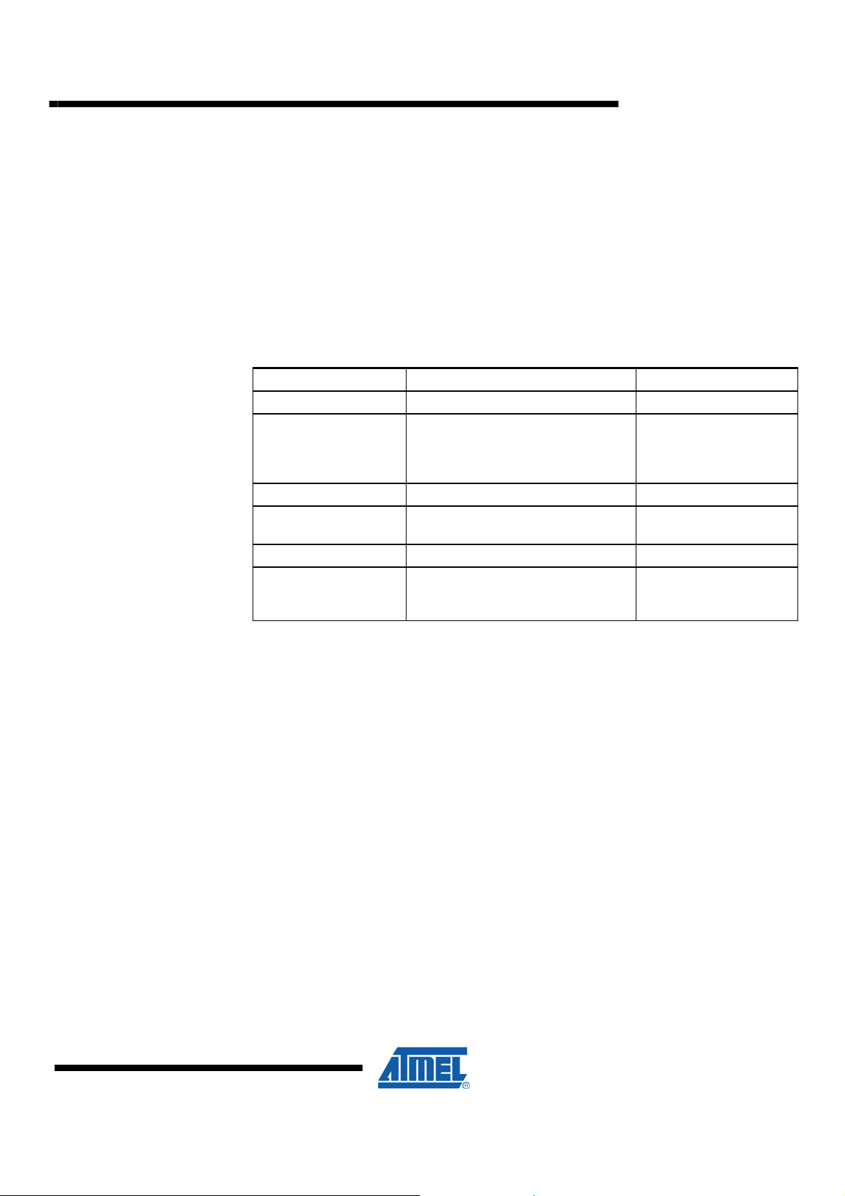
2 Theory of operation
The communication protocol operates in a master – slave environment, AVR Studio
being the master and JTAGICE mkII being the slave.
The JTAGICE mkII slave is always operating in one of three states (with
enumeration):
1. STOPPED
2. RUNNING
3. PROGRAMMING
Some commands can only be executed while the slave is in STOPPED mode, others
may be allowed in all modes. The details are described for each different command.
Events are messages sent from the slave with no prior commands given from the
master.
Serial communication is asynchronous by nature, so is the JTAGICE mkII protocol. All
commands and responses have tokens and CRC checks included enabling the
receiver to verify the validity of the received message.
This transport protocol guarantees that every packet that is received is verified
correctly, but it does not guarantee that every packet is received. Retransmission and
lost packets are to be handled by the application layer, not the transmission layer.
When USB is used, the hardware layer handles retransmission automatically. This is
not the case with RS232.
The protocol is “Little Endean”, LSB is always transferred first in memory addresses.
2.1 USB and RS-232 Connection
The JTAGICE mkII has both a USB and an RS-232 interface for connecting to a host
computer. They share the same message format (see section 3).
USB is preferred due to speed.
2.1.1 RS-232 Connection
The RS-232 connection’s power-on settings are 19,200 bps, 8N1, no handshake.
However, using the Set Parameter command and the Baud rate parameter, the baud
rate can be changed.
2.1.2 USB Connection
The JTAGICE mkII has a USB port capable of USB full-speed connection (12Mbps).
In addition to data transfer, the USB cable can also supply power to the emulator, so
no external power is required. After enumeration, the emulator can draw up to 500mA
from the USB hub.
2.1.3 USB Configuration
The JTAGICE mkII has one configuration with one interface containing two bulk
transfer endpoints. The USB descriptors can be found in section 7.
The JTAGICE mkII messages are transferred through the bulk endpoints. Maximum
packet size is shown in the endpoint descriptors.
2
AVR067
2587D-AVR-11/09
3 Message Format
http://www.BDTIC.com/ATMEL
In addition to the framing mechanisms supplied by the JTAGICE mkII frame format,
the emulator uses short packets (both IN and OUT endpoints) to indicate which USB
packet is the last one in a JTAGEICE mkII frame. The host driver must also support
short packets.
All commands, responses and events share a common message format:
<MESSAGE_START, SEQUENCE_NUMBER, MESSAGE_SIZE, TOKEN,
MESSAGE_BODY, CRC>
Table 3-1. Parameters of messages.
Parameter Name Usage Format
MESSAGE_START ASCII 27 (ESC character) [BYTE]
SEQUENCE_NUMBER
MESSAGE_SIZE Size of the message body in bytes [BYTE]*4, LSB first
TOKEN
MESSAGE_BODY Message body [BYTE]*MESSAGE_SIZE
CRC
First byte of the message body is always the MESSAGE_ID. The size of the
MESSAGE_BODY is at least 1 byte.
Incremented by one for each
message sent. Wraps to zero after
0xFFFE. 0xFFFF is reserved for
(asynchronous) EVENTS.
ASCII 14, making the protocol more
robust.
Uses all characters in message
including MESSAGE_START and
MESSAGE_BODY.
[BYTE]*2, LSB first.
[BYTE]
[BYTE]*2
AVR067
4 Message parsing
4.1 Introduction
2587D-AVR-11/09
• Messages use MESSAGE_ID in the range from 0x01 to 0x3F
• Success responses use MESSAGE_ID in the range from 0x80 to 0x9F
• Failure responses use MESSAGE_ID in the range from 0xA0 to 0xBF
• Events use MESSAGE_ID in the range from 0xE0 to 0xFF
• Message start is ASCII 27 (0x1B), not to be changed.
• Token is ASCII 14 (0x0E), not to be changed.
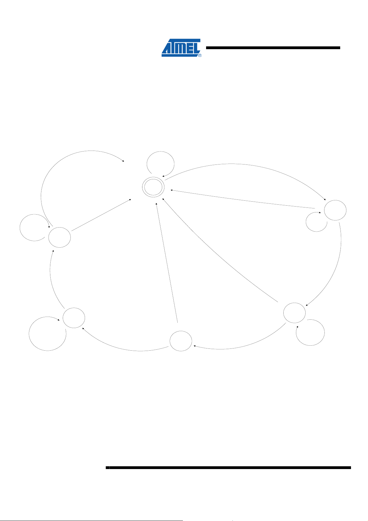
Messages either way should be read as a byte stream by a state machine. Every time
a MESSAGE_START character occurs, the state machine starts to decode the
message, either completing the message or falling out of the byte stream if a
message rule is violated.
Messages can come in any order and there is no specific timing regarding required
timeframes between commands. The emulator implements a message queue, when
the state machine has parsed and verified a complete message it is serialized and put
on a message queue. The emulator executes the messages in the sequence found
3
http://www.BDTIC.com/ATMEL
on the queue. Responses to the messages are given when they are processed by the
emulator.
The same state machine is used for both RS232 and USB transmission. An interrupt
routine on the communication control processor in the JTAGICE mkII reads the
appropriate UART and puts the incoming data in a FIFO implemented in SRAM. The
state machine reads and parses the data from the FIFO.
4.2 Common State Machine Implementation
Figure 4-1. State Diagram
Char < > A S CII 27
E: CRC byte 0
C: nmb char ==
MESSAGE_SIZE
E: New char
C: nmb char <
MESSAGE_SIZE
CRC
E: New char
Get D a ta
E: CR C b yte 1
C: CRC illegal
A: Clear buffers
update statistics
E: CR C b yte 1
C: CRC legal
A: Store complete
message in queue.
E: Legal Token
C: Message Size > 0
A: Start timeout timer
Start
E: Illegal Token
A: Clear message
buffer, update illegal
message statistics
Get Token
E: Cha r = = A SCII27
A: Start timeout timer
A: Send Timeout
response to master
E: Timeout
A: Send Timeout
Response to Master
E: Message Size
Complete
A: Start Timeout Timer
E: Timeout
Get
Message
Size
Read bytes 0-2
Get
Sequence
Number
Read bytes 0-1
E: Message ID read
A: Start Timeout Timer
4
AVR067
2587D-AVR-11/09
http://www.BDTIC.com/ATMEL
AVR067
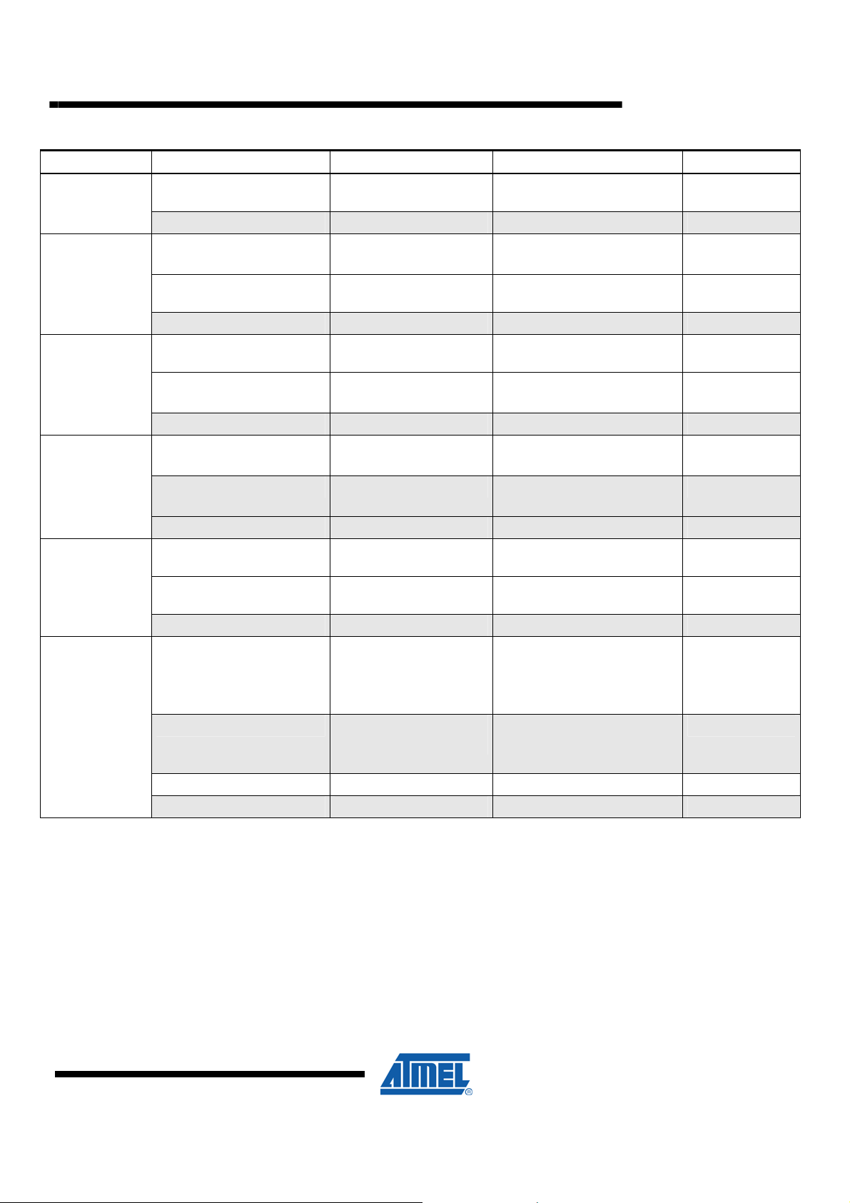
Table 4-1. State table. Gray fields represent “message failed”, non grayed fields are “message valid”.
Current State Event Condition Action Next State
Start
Get Sequence
Number
Get Message
Size
Get Token
Get Data
Get CRC
Read character from inbuf Char == ASCII 27 Start timeout timer
Read character from inbuf Char <> ASCII 27 None Start
Read character from inbuf
Read character from inbuf
Timeout None Update message statistics Start
Read character from inbuf
Read character from inbuf
Timeout None Update message statistics Start
Read character from inbuf Char == ASCII 14 Start timeout timer
Read character from inbuf Char <> ASCII 14 Update message statistics
Timeout None Update message statistics Start
Read character from inbuf
Read character from inbuf
Timeout None Update message statistics Start
Read character from inbuf CRC Byte Count == 2
Read character from inbuf CRC Byte Count == 2
Read character from inbuf CRC Byte Count < 2 Start timeout timer Get CRC
Timeout None Update message statistics Start
Sequence Number Byte
Counter == 2
Sequence Number Byte
Counter < 2
Message Size Byte
Counter < 4
Message Size Byte
Counter ==4
Nmb char read ==
MESSAGE_SIZE
Nmb char read <
MESSAGE_SIZE
CRC OK
CRC NOT OK
Start timeout timer
Start timeout timer
Start timeout timer Get Message Size
Start timeout timer
Calculate MESSAGE_SIZE
Stop timeout timer
Start timeout timer Get CRC
Start timeout timer Get Data
Calculate CRC
Update message statistics
Execute command
Stop timeout timer
Calculate CRC
Update message statistics
Stop timeout timer
Get Sequence
Number
Get Message Size
Get Sequence
Number
Get Token
Get Data
Start
Start
Start
5 Commands and responses
5.1 Master Commands
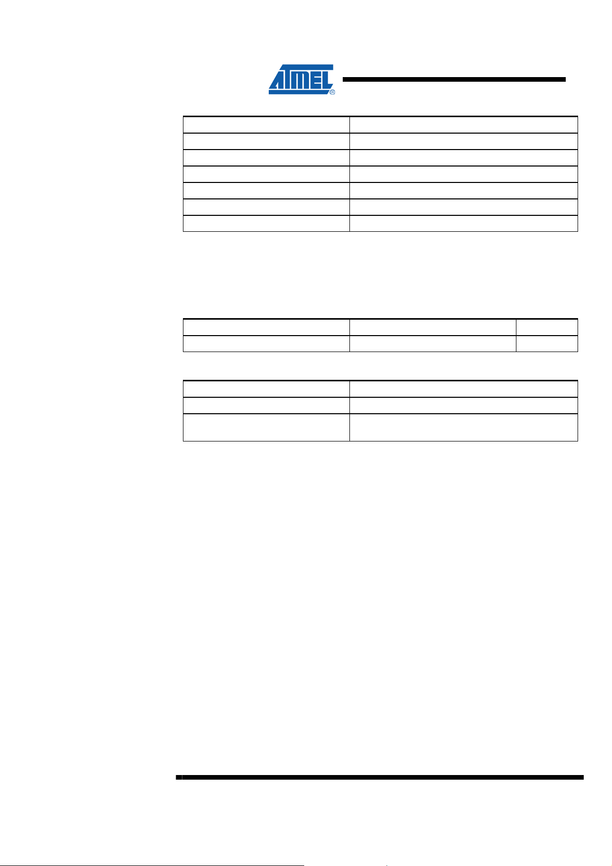
5.1.1 Sign off (CMND_SIGN_OFF: 0x00)
The master issues this command when it terminates a debugging session.
Slave state: All states.
2587D-AVR-11/09
5
http://www.BDTIC.com/ATMEL
Table 5-1. Message Format
Parameter Name Description
MESSAGE_START ASCII 27 (ESC character)
SEQUENCE_NUMBER Incremented for each packet sent.
MESSAGE_SIZE 0x01
TOKEN ASCII 14
MESSAGE_BODY None
CRC 2-byte CRC.
The MESSAGE_BODY consists of:
<MESSAGE_ID>
Table 5-2. Parameters
Parameter Name Usage Format
MESSAGE_ID 0x00 (CMND_SIGN_OFF) [BYTE]
Table 5-3. Response
Parameter Name Description
RSP_OK The command was executed.
RSP_FAILED
The JTAGICE mkII is there, but it did not understand
the command.
6
AVR067
2587D-AVR-11/09
http://www.BDTIC.com/ATMEL
5.1.2 Check if Emulator is present (CMND_GET_SIGN_ON: 0x01)
The master uses this command to see if an emulator is attached and alive.
Slave state: All states.
Table 5-4. Message Format.
Parameter Name Description
MESSAGE_START ASCII 27 (ESC character)
SEQUENCE_NUMBER Incremented for each packet sent.
MESSAGE_SIZE 0x01
TOKEN ASCII 14
MESSAGE_BODY None
CRC 2-byte CRC.
The MESSAGE_BODY consists of:
<MESSAGE_ID>
AVR067
Table 5-5. Parameters.
Parameter Name Usage Format
MESSAGE_ID 0x01 (CMND_GET_SIGN_ON) [BYTE]
Table 5-6. Response.
Parameter Name Description
RSP_SIGN_ON
RSP_FAILED
TIMEOUT
Garbage
Contains sign on string for JTAGICE mkII.
Compatibility issues with other emulators must be
resolved.
Sign on (RSP_SIGN_ON : 0x86)
The JTAGICE mkII is there, but it did not understand
the command.
No slave response within the defined timeout time.
The slave is either not there, or it is not turned on.
If serial communication is used, HW error UART
configuration error (wrong baud rate, parity bit setting
etc)
If USB communication is used, HW error.
2587D-AVR-11/09
7
http://www.BDTIC.com/ATMEL
5.1.3 Write Emulator Parameter (CMND_SET_PARAMETER: 0x02)
The emulator hosts a number of set-up parameters. This command is used to write all
parameters. The parameter ID identifies the parameter written.
Slave state: Depending on the parameter.
Table 5-7. Message Format.
Parameter Name Description
MESSAGE_START ASCII 27 (ESC character)
SEQUENCE_NUMBER Incremented for each packet sent.
MESSAGE_SIZE The size of the MESSAGE_BODY in bytes.
TOKEN ASCII 14
MESSAGE_BODY See below
CRC 2-byte CRC.
The message body consists of:
<MESSAGE_ID, PARAMETER_ID, PARAMETER_VALUE>
Table 5-8. Parameters.
Parameter Name Usage Format
MESSAGE_ID 0x02 (CMND_SET_PARAMETER) [BYTE]
PARAMETER_ID Parameter ID [BYTE]
PARAMETER_VALUE Parameter value, can be of any size
[BYTE] * N,
LSB first if
applicable.
Table 5-9. Response.
Parameter Name Description
RSP_OK The parameter is written OK.
RSP_FAILED
RSP_ILLEGAL_PARAMETER
RSP_ILLEGAL_VALUE The given value was invalid or out or range
RSP_ILLEGAL_EMULATOR_MODE
Timeout No response from the slave within the timeout time.
The command was not understood by the JTAGICE
mkII
The JTAGICE mkII does not support the selected
parameter (AVR Studio 4 – JTAGICE mkII FW
incompatibility).
The operation cannot be performed in this emulator
mode. (JTAG / debugWire).
The parameter description is found in a later section in this document.
8
AVR067
2587D-AVR-11/09
5.1.4 Read Emulator Parameter (CMND_GET_PARAMETER: 0x03)
http://www.BDTIC.com/ATMEL
Reads emulator set-up parameters back to AVR Studio. Parameter descriptions
found in a later section in this document.
Slave state: Depending on the parameter.
Table 5-10. Message Format.
Parameter Name Description
MESSAGE_START ASCII 27 (ESC character)
SEQUENCE_NUMBER Incremented for each packet sent.
MESSAGE_SIZE 0x02
TOKEN ASCII 14
MESSAGE_BODY Defined below
CRC 2-byte CRC.
The MESSAGE_BODY consists of:
<MESSAGE_ID, PARAMETER_ID>
Table 5-11. Parameters.
Parameter Name Usage Format
MESSAGE_ID 0x03 (CMND_GET_PARAMETER) [BYTE]
PARAMETER_ID The requested emulator parameter [BYTE]
AVR067
Table 5-12. Response.
Parameter Name Description
RSP_PARAMETER Returns the requested parameter.
RSP_FAILED
RSP_ILLEGAL_PARAMETER
RSP_ILLEGAL_EMULATOR_MODE
Timeout No response from the slave within the timeout time.
5.1.5 Write Memory (CMND_WRITE_MEMORY: 0x04)
Write a memory block to any address in any memory area.
Slave state: STOPPED.
Table 5-13. Message Format.
Parameter Name Description
MESSAGE_START ASCII 27 (ESC character)
SEQUENCE_NUMBER Incremented for each packet sent.
MESSAGE_SIZE The size of the MESSAGE_BODY in bytes.
Parameter return (RSP_PARAMETER : 0x81)
The command was not understood by the JTAGICE
mkII
The JTAGICE mkII does not support the selected
parameter (AVR Studio 4 – JTAGICE mkII FW
incompatibility).
The operation cannot be performed in this emulator
mode. (JTAG / debugWire).
2587D-AVR-11/09
9
http://www.BDTIC.com/ATMEL
Parameter Name Description
TOKEN ASCII 14
MESSAGE_BODY See below
CRC 2-byte CRC.
The MESSAGE_BODY consists of:
<MESSAGE_ID, MEMORY_TYPE, BYTE_COUNT, START_ADDRESS, DATA>
Table 5-14. Parameters.
Parameter Name Usage Format
MESSAGE_ID 0x04 (CMND_WRITE_MEMORY) [BYTE]
MEMORY_TYPE
BYTE_COUNT Number of bytes to be written
START_ADDRESS Start memory address
DATA The data
Memory type (Flash, SRAM,
EEPROM...)
[BYTE]
[BYTE]*4 LSB
first
[BYTE]*4 LSB
first
[BYTE] *
BYTE_COUNT
Definitions and parameter values of the different memory types are found in the
Memory Types section.
Table 5-15. Response.
Parameter Name Description
RSP_OK The memory is written OK.
RSP_FAILED
RSP_ILLEGAL_MEMORY_TYPE
RSP_ILLEGAL_MEMORY_RANGE
RSP_ILLEGAL_EMULATOR_MODE
RSP_ILLEGAL_MCU_STATE
Timeout No response from the slave within the timeout time.
The command was not understood by the JTAGICE
mkII
The JTAGICE mkII does not support the selected
memory.
The memory write was outside the bounds of the
selected memory area.
The operation cannot be performed in this emulator
mode. (JTAG / debugWire).
The operation cannot be performed with the target
MCU in its current state.
10
AVR067
2587D-AVR-11/09
http://www.BDTIC.com/ATMEL
5.1.6 Read Memory (CMND_READ_MEMORY: 0x05)
Read a memory block from any address in any memory area.
Slave state: STOPPED
Table 5-16. Message Format.
Parameter Name Description
MESSAGE_START ASCII 27 (ESC character)
SEQUENCE_NUMBER Incremented for each packet sent.
MESSAGE_SIZE 10 bytes.
TOKEN ASCII 14
MESSAGE_BODY See below
CRC 2-byte CRC.
The MESSAGE_BODY consists of:
<MEMORY_TYPE, BYTE_COUNT, START_ADDRESS>
AVR067
Table 5-17. Parameters.
Parameter Name Usage Format
MESSAGE_ID 0x05 (CMND_READ_MEMORY) [BYTE]
MEMORY_TYPE
BYTE_COUNT Number of bytes to be read
START_ADDRESS Start memory address
Memory type (Flash, SRAM,
EEPROM...)
[BYTE]
[BYTE]*4 LSB
first
[BYTE]*4 LSB
first
Definitions and parameter values of the different memory types are found in the
Memory Types section.
Table 5-18. Response.
Parameter Name Description
RSP_MEMORY The memory is read OK.
Memory read (RSP_MEMORY : 0x82)
RSP_FAILED
RSP_ILLEGAL_MEMORY_TYPE
RSP_ILLEGAL_MEMORY_RANGE
RSP_ILLEGAL_EMULATOR_MODE
The command was not understood by the JTAGICE
mkII
The JTAGICE mkII does not support the selected
memory.
The memory write was outside the bounds of the
selected memory area.
The operation cannot be performed in this emulator
mode. (JTAG / debugWire).
2587D-AVR-11/09
11
http://www.BDTIC.com/ATMEL
Parameter Name Description
RSP_ILLEGAL_MCU_STATE
Timeout No response from the slave within the timeout time.
5.1.7 Write Program Counter (CMND_WRITE_PC: 0x06)
Writes the AVR Program Counter.
Slave state: STOPPED.
Table 5-19. Message Format.
Parameter Name Description
MESSAGE_START ASCII 27 (ESC character)
SEQUENCE_NUMBER Incremented for each packet sent.
MESSAGE_SIZE 5
TOKEN ASCII 14
MESSAGE_BODY See below.
CRC 2-byte CRC.
The operation cannot be performed with the target
MCU in its current state.
The MESSAGE_BODY consists of:
<MESSAGE_ID, PROGRAM_COUNTER>
Table 5-20. Parameters.
Parameter Name Usage Format
MESSAGE_ID 0x06 (CMND_WRITE_PC) [BYTE]
PROGRAM_COUNTER Program Counter
[BYTE]*4 LSB
first.
Table 5-21. Response.
Parameter Name Description
RSP_OK The program counter was written OK.
RSP_FAILED
RSP_ILLEGAL_EMULATOR_MODE
RSP_ILLEGAL_MCU_STATE
Timeout No response from the slave within the timeout time.
The command was not understood by the JTAGICE
mkII
The operation cannot be performed in this emulator
mode. (JTAG / debugWire).
The operation cannot be performed with the target
MCU in its current state.
5.1.8 Read Program Counter (CMND_READ_PC: 0x07)
Reads the AVR Program Counter.
12
AVR067
2587D-AVR-11/09
http://www.BDTIC.com/ATMEL
AVR067
Slave state: STOPPED.
Table 5-22. Message Format.
Parameter Name Description
MESSAGE_START ASCII 27 (ESC character)
SEQUENCE_NUMBER Incremented for each packet sent.
MESSAGE_SIZE 1
TOKEN ASCII 14
MESSAGE_BODY See below.
CRC 2-byte CRC.
The MESSAGE_BODY consists of:
<MESSAGE_ID>
Table 5-23. Parameters.
Parameter Name Usage Format
MESSAGE_ID 0x07 (CMND_READ_PC) [BYTE]
Table 5-24. Response.
Parameter Name Description
RSP_PC The program counter is returned.
Program Counter Read (RSP_PC : 0x84)
RSP_FAILED
RSP_ILLEGAL_EMULATOR_MODE
RSP_ILLEGAL_MCU_STATE
Timeout No response from the slave within the timeout time.
The command was not understood by the JTAGICE
mkII
The operation cannot be performed in this emulator
mode. (JTAG / debugWire).
The operation cannot be performed with the target
MCU in its current state.
2587D-AVR-11/09
13
http://www.BDTIC.com/ATMEL
5.1.9 Start Program Execution (CMND_GO: 0x08)
Starts program execution at current Program Counter address.
Slave state: STOPPED or RUNNING. When the command is executed the state
either changes to or remains in RUNNING.
Table 5-25. Message Format.
Parameter Name Description
MESSAGE_START ASCII 27 (ESC character)
SEQUENCE_NUMBER Incremented for each packet sent.
MESSAGE_SIZE 1
TOKEN ASCII 14
MESSAGE_BODY None
CRC 2-byte CRC.
The MESSAGE_BODY consists of:
< MESSAGE_ID >
Table 5-26. Parameters.
Parameter Name Usage Format
MESSAGE_ID CMND_GO : 0x08 [BYTE]
Table 5-27. Response.
Parameter Name Description
RSP_OK The command was executed.
RSP_FAILED
RSP_ILLEGAL_EMULATOR_MODE
Timeout No response from the slave within the timeout time.
5.1.10 Single Step (CMND_SINGLE_STEP: 0x09)
Starts one-step execution at current Program Counter address.
Slave state: STOPPED. After execution the slave is in RUNNING state until it hits the
next breakpoint. Then a Break Event is issued, and the slave returns to STOPPED
state.
The command was not understood by the JTAGICE
mkII
The operation cannot be performed in this emulator
mode. (JTAG / debugWire).
Table 5-28. Message Format.
Parameter Name Description
MESSAGE_START ASCII 27 (ESC character)
14
AVR067
2587D-AVR-11/09
http://www.BDTIC.com/ATMEL
Parameter Name Description
SEQUENCE_NUMBER Incremented for each packet sent.
MESSAGE_SIZE 3
TOKEN ASCII 14
MESSAGE_BODY High level or low level flag, see below.
CRC 2-byte CRC.
AVR067
The MESSAGE_BODY consists of:
<MESSAGE_ID, FLAG>
Table 5-29. Parameters.
Parameter Name Usage Format
MESSAGE_ID 0x09 (CMND_SINGLE_STEP) [BYTE]
FLAG 0x01 : Low level
0x02 : High level.
STEP_MODE 0x00: STEP_OVER
0x01: STEP_INTO
0x02: STEP_OUT
[BYTE]
[BYTE]
Table 5-30. Response.
Parameter Name Description
RSP_OK The command is executed.
RSP_FAILED
RSP_ILLEGAL_EMULATOR_MODE
RSP_ILLEGAL_MCU_STATE
Timeout No response from the slave within the timeout time.
5.1.11 Stop Program Execution (CMND_FORCED_STOP: 0x0A)
Stops program execution.
Slave state: STOPPED or RUNNING. After execution of the command the slave is in
STOPPED state.
Table 5-31. Message Format.
Parameter Name Description
MESSAGE_START ASCII 27 (ESC character)
SEQUENCE_NUMBER Incremented for each packet sent.
MESSAGE_SIZE 2 Bytes
TOKEN ASCII 14
MESSAGE_BODY See below
CRC 2-byte CRC.
The command was not understood by the JTAGICE
mkII
The operation cannot be performed in this emulator
mode. (JTAG / debugWire).
The operation cannot be performed with the target
MCU in its current state.
2587D-AVR-11/09
15
http://www.BDTIC.com/ATMEL
The MESSAGE_BODY consists of:
<MESSAGE_ID, MODE>
Table 5-32. Parameters.
Parameter Name Usage Format
MESSAGE_ID 0x0A (CMND_FORCED_STOP) [BYTE]
MODE 0x01: LOW LEVEL
0x02: HIGH LEVEL
(stops at next high level statement)
Table 5-33. Response.
Parameter Name Description
RSP_OK The command is executed.
RSP_FAILED
RSP_ILLEGAL_EMULATOR_MODE
Timeout No response from the slave within the timeout time.
The command was not understood by the JTAGICE
mkII
The operation cannot be performed in this emulator
mode. (JTAG / debugWire).
[BYTE]
5.1.12 Reset User Program (CMND_RESET: 0x0B)
Emulator performs all actions to restart program execution
Slave state: Any. If the slave is in RUNNING mode prior to this operation, the slave
will change to STOPPED state prior to the execution of this command
Table 5-34. Message Format.
Parameter Name Description
MESSAGE_START ASCII 27 (ESC character)
SEQUENCE_NUMBER Incremented for each packet sent.
MESSAGE_SIZE Size of message body
TOKEN ASCII 14
MESSAGE_BODY See below
CRC 2-byte CRC.
High level or low level flag. High level typically
returns to main. Give a procedure. Give low level
reset with “run afterwards”.
16
AVR067
2587D-AVR-11/09
http://www.BDTIC.com/ATMEL
AVR067
The MESSAGE_BODY consists of:
<MESSAGE_ID, FLAG>
Table 5-35. Parameters.
Parameter Name Usage Format
MESSAGE_ID 0x0B (CMND_RESET) [BYTE]
FLAG 0x01: Low level
0x02: High level (reset, then run to
main)
0x04: Reset with debugWire
disable.
[BYTE]
Table 5-36. Response.
Parameter Name Description
RSP_OK The command is executed.
RSP_FAILED
RSP_ILLEGAL_EMULATOR_MODE
Timeout No response from the slave within the timeout time.
The command was not understood by the JTAGICE
mkII
The operation cannot be performed in this emulator
mode. (JTAG / debugWire).
5.1.13 Set Device Descriptor (CMND_SET_DEVICE_DESCRIPTOR: 0x0C)
Transmits all parameters relevant for a specific device set-up
Slave state: STOPPED.
Table 5-37. Message Format.
Parameter Name Description
MESSAGE_START ASCII 27 (ESC character)
SEQUENCE_NUMBER Incremented for each packet sent.
MESSAGE_SIZE Size of message body
TOKEN ASCII 14
MESSAGE_BODY All parameters for a specific device set-up.
CRC 2-byte CRC.
The MESSAGE_BODY consists of:
<MESSAGE_ID, PARAMETERS>
Table 5-38. Parameters.
Parameter Name Usage Format
MESSAGE_ID
0x0C
(CMND_SET_DEVICE_DESCRIPTOR)
[BYTE]
2587D-AVR-11/09
17
http://www.BDTIC.com/ATMEL
Parameter Name Usage Format
PARAMETERS
Table 5-39. Response.
Parameter Name Description
RSP_OK The command is executed.
RSP_FAILED
RSP_ILLEGAL_EMULATOR_MODE
RSP_ILLEGAL_MCU_STATE
Timeout No response from the slave within the timeout time.
5.1.14 Erase Page SPM (CMND_ERASEPAGE_SPM: 0x0D)
Erases a whole page in Flash memory
All parameters required to set up a
device in raw binary form, identical to the
JTAGICE descriptor.
The command was not understood by the JTAGICE
mkII
The operation cannot be performed in this emulator
mode. (JTAG / debugWire).
The operation cannot be performed with the target
MCU in its current state.
[BYTE] *
298
Slave state: STOPPED
Table 5-40. Message Format.
Parameter Name Description
MESSAGE_START ASCII 27 (ESC character)
MESSAGE_ID 0x0D (CMND_ERASEPAGE_SPM)
SEQUENCE_NUMBER Incremented for each packet sent.
MESSAGE_SIZE 5
TOKEN ASCII 14
MESSAGE_BODY See below
CRC 2-byte CRC.
The MESSAGE_BODY consists of:
<MESSAGE_ID, PAGE_ADDRESS>
Table 5-41. Parameters.
Parameter Name Usage Format
MESSAGE_ID
PAGE_ADDRESS Address to the page to be erased
0x0D
(CMND_ERASEPAGE_SPM)
[BYTE]
[BYTE]*4, LSB
first
Table 5-42. Response.
Parameter Name Description
18
AVR067
2587D-AVR-11/09
Parameter Name Description
http://www.BDTIC.com/ATMEL
RSP_OK The command is executed.
RSP_FAILED
RSP_ILLEGAL_EMULATOR_MODE
RSP_ILLEGAL_MCU_STATE
Timeout No response from the slave within the timeout time.
5.1.15 Get Sync (CMND_GET_SYNC 0x0F)
Sent from AVR Studio in order to regain synchronization with JTAGICE mkII, if lost
Table 5-43. Message Format.
Parameter Name Description
MESSAGE_START ASCII 27 (ESC character)
SEQUENCE_NUMBER Incremented for each packet sent.
MESSAGE_SIZE 1
TOKEN ASCII 14
MESSAGE_BODY See below
CRC 2-byte CRC.
The command was not understood by the JTAGICE
mkII
The operation cannot be performed in this emulator
mode. (JTAG / debugWire).
The operation cannot be performed with the target
MCU in its current state.
AVR067
The MESSAGE_BODY consists of:
<MESSAGE_ID>
Table 5-44. Parameters.
Parameter Name Usage Format
MESSAGE_ID 0x0F (CMND_GET_SYNC) [BYTE]
Table 5-45. Response.
Parameter Name Description
RSP_OK The command is executed.
RSP_FAILED
Timeout No response from the slave within the timeout time.
5.1.16 Self test (CMND_SELFTEST: 0x10)
Makes the JTAGICE mkII perform self test and report back to the master.
Slave state: STOPPED
Table 5-46. Message Format.
Parameter Name Description
The command was not understood by the JTAGICE
mkII.
2587D-AVR-11/09
19
http://www.BDTIC.com/ATMEL
Parameter Name Description
MESSAGE_START ASCII 27 (ESC character).
SEQUENCE_NUMBER Incremented for each packet sent.
MESSAGE_SIZE Size of message body.
TOKEN ASCII 14
MESSAGE_BODY Parameters for self test (choose what to test).
CRC 2-byte CRC.
The MESSAGE_BODY consists of:
<MESSAGE_ID, FLAGS>
Table 5-47. Parameters.
Parameter Name Usage Format
MESSAGE_ID 0x10 (CMND_SELFTEST) [BYTE]
FLAGS
FLAGS identifying which tests to be
performed.
bit 7: internal tests (SRAM, FIFO…)
bit 6: <not used>
bit 5: <not used>
bit 4: <not used>
bit 3: STK500 RESET JUMPER
detector
bit 2: JTAG PUSH PULL
bit 1: debugWire Capacitance
bit 0: debugWire PUSH PULL
[BYTE]
Table 5-48. Response.
Parameter Name Description
RSP_SELFTEST The command is executed.
RSP_FAILED
RSP_ILLEGAL_EMULATOR_MODE
RSP_ILLEGAL_MCU_STATE
Timeout No response from the slave within the timeout time.
5.1.17 Set Breakpoint (CMND_SET_BREAK: 0x11)
Set a breakpoint. (For hardware breakpoints on megaAVR devices with JTAG
interface only, and software breakpoints)
Slave state: STOPPED
20
AVR067
Selftest (RSP_SELFTEST : 0x85)
The command was not understood by the JTAGICE
mkII.
The operation cannot be performed in this emulator
mode. (JTAG / debugWire).
The operation cannot be performed with the target
MCU in its current state.
2587D-AVR-11/09
http://www.BDTIC.com/ATMEL
AVR067
Table 5-49. Message Format.
Parameter Name Description
MESSAGE_START ASCII 27 (ESC character)
SEQUENCE_NUMBER Incremented for each packet sent.
MESSAGE_SIZE Size of message body
TOKEN ASCII 14
MESSAGE_BODY Breakpoint setting (see format below).
CRC 2-byte CRC.
The MESSAGE_BODY consists of:
<MESSAGE_ID, TYPE, NUMBER, ADDRESS, MODE>
Table 5-50. Parameters.
Parameter Name Usage Format
MESSAGE_ID 0x11 (CMND_SET_BREAK) [BYTE]
TYPE 0x01: program memory breakpoint
0x02: data breakpoint
0x03:mask for data breakpoint
NUMBER
ADDRESS Break address of mask value
MODE 0x00: Break on memory read
Breakpoint number, 0x01 to 0x04
(up to 4 breakpoints are supported
0x00 for SW BP
0x01: Break on memory write
0x02: Break on memory read or
write.
0x03: Program breakpoint
[BYTE]
[BYTE]
[BYTE] * 4,
LSB first
[BYTE]
2587D-AVR-11/09
21

http://www.BDTIC.com/ATMEL
Table 5-51. Response.
Parameter Name Description
RSP_OK The command is executed.
RSP_FAILED
RSP_ILLEGAL_BREAKPOINT The breakpoint number does not exist.
RSP_ILLEGAL_EMULATOR_MODE
RSP_ILLEGAL_MCU_STATE
RSP_ILLEGAL_BREAKPOINT
Timeout No response from the slave within the timeout time.
5.1.18 Get Breakpoint (CMND_GET_BREAK: 0x12)
Used by the host to read back the current breakpoint setting in the JTAGICE mkII.
(For hardware breakpoints on megaAVR devices with JTAG interface only, and
software breakpoints)
The command was not understood by the JTAGICE
mkII.
Illegal breakpoint (RSP_ILLEGAL_BREAKPOINT:
0xA8)
The operation cannot be performed in this emulator
mode. (JTAG / debugWire).
The operation cannot be performed with the target
MCU in its current state.
The breakpoint number is not supported (in this
mode)
Slave state: STOPPED
Table 5-52. Message Format.
Parameter Name Description
MESSAGE_START ASCII 27 (ESC character)
SEQUENCE_NUMBER Incremented for each packet sent.
MESSAGE_SIZE 2
TOKEN ASCII 14
MESSAGE_BODY See below
CRC 2-byte CRC.
The MESSAGE_BODY consists of:
<MESSAGE_ID, NUMBER>
Table 5-53. Parameters.
Parameter Name Usage Format
MESSAGE_ID 0x12 (CMND_GET_BREAK) [BYTE]
NUMBER
Breakpoint number, 0x01 to 0x04
(up to 4 breakpoints are supported
[BYTE]
Table 5-54. Response.
Parameter Name Description
22
AVR067
2587D-AVR-11/09
Parameter Name Description
http://www.BDTIC.com/ATMEL
RSP_GET_BREAK The command is executed, breakpoint returned.
RSP_FAILED
RSP_ILLEGAL_EMULATOR_MODE
RSP_ILLEGAL_MCU_STATE
RSP_ILLEGAL_BREAKPOINT
Timeout No response from the slave within the timeout time.
5.1.19 Chip erase (CMD_CHIP_ERASE: 0x13)
Used in order to do a complete chip erase. (megaAVR devices with JTAG interface
only. Devices with debugWire interface automatically erase flash pages before
programming. XMEGA devices use dedicated XMEGA Erase function, detailed later
in this document. )
Breakpoint read (RSP_GET_BREAK: 0x83)
The command was not understood by the JTAGICE
mkII
The operation cannot be performed in this emulator
mode. (JTAG / debugWire).
The operation cannot be performed with the target
MCU in its current state.
The breakpoint number is not supported (in this
mode)
AVR067
Table 5-55. Message Format.
Parameter Name Description
MESSAGE_START ASCII 27 (ESC character)
SEQUENCE_NUMBER Incremented for each packet sent.
MESSAGE_SIZE 1
TOKEN ASCII 14
MESSAGE_BODY See below
CRC 2-byte CRC.
The MESSAGE_BODY consists of:
<MESSAGE_ID>
Table 5-56. Parameters.
Parameter Name Usage Format
MESSAGE_ID 0x13 (CMD_CHIP_ERASE) [BYTE]
Table 5-57. Response.
Parameter Name Description
RSP_OK The command is executed.
RSP_FAILED
RSP_ILLEGAL_EMULATOR_MODE
The command was not understood by the JTAGICE
mkII
The operation cannot be performed in this emulator
mode. (JTAG / debugWire).
2587D-AVR-11/09
23

http://www.BDTIC.com/ATMEL
Parameter Name Description
RSP_ILLEGAL_MCU_STATE
Timeout No response from the slave within the timeout time.
5.1.20 Enter programming mode (CMND_ENTER_PROGMODE: 0x14)
Enter programming mode.
Table 5-58. Message Format.
Parameter Name Description
MESSAGE_START ASCII 27 (ESC character)
SEQUENCE_NUMBER Incremented for each packet sent.
MESSAGE_SIZE 1
TOKEN ASCII 14
MESSAGE_BODY See below
CRC 2-byte CRC.
The MESSAGE_BODY consists of:
The operation cannot be performed with the target
MCU in its current state.
<MESSAGE_ID>
Table 5-59. Parameters.
Parameter Name Usage Format
MESSAGE_ID
0x14
(CMND_ENTER_PROGMODE)
[BYTE]
Table 5-60. Response.
Parameter Name Description
RSP_OK The command is executed.
RSP_FAILED
RSP_ILLEGAL_JTAG_ID
RSP_ILLEGAL_EMULATOR_MODE
RSP_ILLEGAL_MCU_STATE
Timeout No response from the slave within the timeout time.
The command was not understood by the JTAGICE
mkII
The JTAG ID does not match the target device’s.
Illegal JTAG ID (RSP_ILLEGAL_JTAG_ID : 0xA9)
The operation cannot be performed in this emulator
mode. (JTAG / debugWire).
The operation cannot be performed with the target
MCU in its current state.
5.1.21 Leave programming mode (CMND_LEAVE_PROGMODE: 0x15)
Leave programming mode.
24
AVR067
2587D-AVR-11/09

http://www.BDTIC.com/ATMEL
AVR067
Table 5-61. Message Format.
Parameter Name Description
MESSAGE_START ASCII 27 (ESC character)
SEQUENCE_NUMBER Incremented for each packet sent.
MESSAGE_SIZE 1
TOKEN ASCII 14
MESSAGE_BODY See below
CRC 2-byte CRC.
The MESSAGE_BODY consists of:
<MESSAGE_ID>
Table 5-62. Parameters.
Parameter Name Usage Format
MESSAGE_ID
0x15
(CMND_LEAVE_PROGMODE)
[BYTE]
Table 5-63. Response.
Parameter Name Description
RSP_OK The command is executed.
RSP_FAILED
RSP_ILLEGAL_EMULATOR_MODE
RSP_ILLEGAL_MCU_STATE
Timeout No response from the slave within the timeout time.
5.1.22 Clear Breakpoint (CMND_CLR_BREAK: 0x1A)
Clear a breakpoint. (For hardware breakpoints on megaAVR devices with JTAG
interface only, and software breakpoints)
Slave state: STOPPED
Table 5-64. Message Format.
Parameter Name Description
MESSAGE_START ASCII 27 (ESC character)
SEQUENCE_NUMBER Incremented for each packet sent.
MESSAGE_SIZE Size of message body
TOKEN ASCII 14
MESSAGE_BODY Breakpoint setting (see format below).
The command was not understood by the JTAGICE
mkII
The operation cannot be performed in this emulator
mode. (JTAG / debugWire).
The operation cannot be performed with the target
MCU in its current state.
2587D-AVR-11/09
25

http://www.BDTIC.com/ATMEL
Parameter Name Description
CRC 2-byte CRC.
The MESSAGE_BODY consists of:
<MESSAGE_ID, NUMBER, ADDRESS >
Table 5-65. Parameters.
Parameter Name Usage Format
MESSAGE_ID 0x1A (CMND_CLR_BREAK) [BYTE]
NUMBER
ADDRESS Break address (for SW BP)
Table 5-66. Response.
Parameter Name Description
RSP_OK The command is executed.
RSP_FAILED
RSP_ILLEGAL_BREAKPOINT The breakpoint number does not exist.
RSP_ILLEGAL_EMULATOR_MODE
RSP_ILLEGAL_MCU_STATE
RSP_ILLEGAL_BREAKPOINT
Timeout No response from the slave within the timeout time.
Breakpoint number, 0x01 to 0x04
(up to 4 breakpoints are supported
The command was not understood by the JTAGICE
mkII
Illegal breakpoint (RSP_ILLEGAL_BREAKPOINT :
0xA8)
The operation cannot be performed in this emulator
mode. (JTAG / debugWire).
The operation cannot be performed with the target
MCU in its current state.
The breakpoint number is not supported (in this
mode)
[BYTE]
[BYTE] * 4,
LSB first
5.1.23 Run to Address (CMND_RUN_TO_ADDR: 0x1C)
Starts program execution at current Program Counter address and runs to the given
Program Counter Address.
Slave state: STOPPED. When the command is executed the state changes to
RUNNING.
Table 5-67. Message Format.
Parameter Name Description
MESSAGE_START ASCII 27 (ESC character)
SEQUENCE_NUMBER Incremented for each packet sent.
MESSAGE_SIZE 5
TOKEN ASCII 14
MESSAGE_BODY None
26
AVR067
2587D-AVR-11/09

http://www.BDTIC.com/ATMEL
Parameter Name Description
CRC 2-byte CRC.
AVR067
The MESSAGE_BODY consists of:
< MESSAGE_ID, P.C. Address >
Table 5-68. Parameters.
Parameter Name Usage Format
MESSAGE_ID CMND_RUN_TO_ADDR: 0x1C [BYTE]
Program Counter Address to stop at
[BYTE] * 4,
LSB first
Table 5-69. Response.
Parameter Name Description
RSP_OK The command was executed.
RSP_FAILED
RSP_ILLEGAL_EMULATOR_MODE
Timeout No response from the slave within the timeout time.
The command was not understood by the JTAGICE
mkII
The operation cannot be performed in this emulator
mode. (JTAG / debugWire).
5.1.24 Universal SPI command (CMND_SPI_CMD: 0x1D)
Runs a universal SPI command.
Slave state: STOPPED.
Table 5-70. Message Format.
Parameter Name Description
MESSAGE_START ASCII 27 (ESC character)
SEQUENCE_NUMBER Incremented for each packet sent.
MESSAGE_SIZE 5
TOKEN ASCII 14
MESSAGE_BODY None
CRC 2-byte CRC.
The MESSAGE_BODY consists of:
< MESSAGE_ID, COMMAND [4]>
Table 5-71. Parameters.
Parameter Name Usage Format
MESSAGE_ID
CMND_SPI_ENABLE_DW_FUSE :
0x1D
[BYTE]
2587D-AVR-11/09
27

http://www.BDTIC.com/ATMEL
Parameter Name Usage Format
COMMAND 4 byte SPI command [BYTE] * 4
Table 5-72. Response.
Parameter Name Description
RSP_SPI_DATA The command was executed.
RSP_FAILED
RSP_ILLEGAL_EMULATOR_MODE
Timeout No response from the slave within the timeout time.
5.1.25 Clear event memory (CMND_CLEAR_EVENTS: 0x22)
Instructs the JTAGICE mkII to clear its event memory (for SW breakpoints). Must be
called AFTER setting the device descriptor to ensure that only the required amount of
event memory is cleared.
Table 5-73. Message Format.
Parameter Name Description
MESSAGE_START ASCII 27 (ESC character)
SEQUENCE_NUMBER Incremented for each packet sent.
MESSAGE_SIZE 1
TOKEN ASCII 14
MESSAGE_BODY See below
CRC 2-byte CRC.
The command was not understood by the JTAGICE
mkII
The operation cannot be performed in this emulator
mode. (Must be in SPI mode).
28
AVR067
The MESSAGE_BODY consists of:
<MESSAGE_ID >
Table 5-74. Parameters.
Parameter Name Usage Format
MESSAGE_ID 0x22 (CMND_CLEAR_EVENTS) [BYTE]
Table 5-75. Response.
Parameter Name Description
RSP_OK The command is executed.
RSP_FAILED
RSP_ILLEGAL_MCU_STATE
Timeout No response from the slave within the timeout time.
The command was not understood by the JTAGICE
mkII
The operation cannot be performed with the target
MCU in its current state.
2587D-AVR-11/09

5.1.26 Restore target (CMND_RESTORE_TARGET: 0x23)
http://www.BDTIC.com/ATMEL
Instructs the JTAGICE mkII to restore the target device into a state where it can run
freely. This is to be done upon terminating a debug session, before signing off and
before disabling the OCD fuse (for JTAG). The command does the following:
• Stop target
• Replaces SW breakpoints with original instructions
• Reset target
• Run target
Table 5-76. Message Format.
Parameter Name Description
MESSAGE_START ASCII 27 (ESC character)
SEQUENCE_NUMBER Incremented for each packet sent.
MESSAGE_SIZE 1
TOKEN ASCII 14
MESSAGE_BODY See below
CRC 2-byte CRC.
AVR067
The MESSAGE_BODY consists of:
<MESSAGE_ID >
Table 5-77. Parameters.
Parameter Name Usage Format
MESSAGE_ID
Table 5-78. Response.
Parameter Name Description
RSP_OK The command is executed.
RSP_FAILED
RSP_ILLEGAL_MCU_STATE
Timeout No response from the slave within the timeout time.
5.1.27 Encapsulated ISP command (CMND_ISP_PACKET: 0x2F)
Used to send any ISP programming commands to the JTAGICE mkII. An ISP packet
compatible with the AVRISP mkII is encapsulated in a JTAGICE mkII packet. The
JTAGICE mkII then operates on the ISP packet in the same way as the AVRISP mkII.
Table 5-170 shows the ISP commands, which are supported on the JTAGICE mkII
0x23
(CMND_RESTORE_TARGET)
The command was not understood by the JTAGICE
mkII
The operation cannot be performed with the target
MCU in its current state.
[BYTE]
For further information regarding the ISP commands, consult document AVR069:
AVRISP mkII Communication Protocol.
2587D-AVR-11/09
29

http://www.BDTIC.com/ATMEL
Table 5-79. Message Format.
Parameter Name Description
MESSAGE_START ASCII 27 (ESC character)
SEQUENCE_NUMBER Incremented for each packet sent.
MESSAGE_SIZE Size of message body
TOKEN ASCII 14
MESSAGE_BODY See below
CRC 2-byte CRC.
The MESSAGE_BODY consists of:
<MESSAGE_ID, ISP_PACKET>
Table 5-80. Parameters.
Parameter Name Usage Format
MESSAGE_ID 0x2F (CMND_ISP_PACKET) [BYTE]
ISP_PACKET Encapsulated AVRISP data [BYTE] * n
Table 5-81. Response.
Parameter Name Description
RSP_OK The command is executed.
RSP_FAILED
RSP_ILLEGAL_MCU_STATE
Timeout No response from the slave within the timeout time.
The command was not understood by the JTAGICE
mkII
The operation cannot be performed with the target
MCU in its current state.
Table 5-170. Supported AVRISP mkII commands on the JTAGICE mkII
Command Usage
CMD_SET_PARAMETER Sets a parameter
CMD_GET_PARAMETER Reads back a parameter value
CMD_OSCCAL Performs OSCCAL calibration sequence
CMD_LOAD_ADDRESS Loads an address for programming functions
CMD_ENTER_PROGMODE_ISP Puts the target device into programming mode
CMD_LEAVE_PROGMODE_ISP Target device leaves programming mode
CMD_CHIP_ERASE_ISP Perform a chip erase on the target device
CMD_PROGRAM_FLASH_ISP Programs the flash memory on the target device
CMD_READ_FLASH_ISP Reads the flash memory on the target device
CMD_PROGRAM_EEPROM_ISP Programs the EEPROM on the target device
CMD_READ_EEPROM_ISP Reads the EEPROM on the target device
CMD_PROGRAM_FUSE_ISP Programs fuses on the target device
CMD_READ_FUSE_ISP Reads fuses on the target device
30
AVR067
2587D-AVR-11/09

Command Usage
http://www.BDTIC.com/ATMEL
CMD_PROGRAM_LOCK_ISP Programs lock bits on the target device
CMD_READ_LOCK_ISP Reads lock bits on the target device
CMD_READ_SIGNATURE_ISP Reads the signature bytes on the target device
CMD_READ_OSCCAL_ISP Reads the OSCCAL byte on the target device
CMD_SPI_MULTI Generic command used to execute ISP commands
5.1.28 Write JTAG Instruction (CMND_JTAG_INSTR: 0x24)
Write a JTAG Instruction to IR
Table 5-82. Message Format.
Parameter Name Description
MESSAGE_START ASCII 27 (ESC character)
SEQUENCE_NUMBER Incremented for each packet sent.
MESSAGE_SIZE 2
TOKEN ASCII 14
MESSAGE_BODY See below
CRC 2-byte CRC.
AVR067
The MESSAGE_BODY consists of:
<MESSAGE_ID, IR_VALUE>
Table 5-83. Parameters.
Parameter Name Usage Format
MESSAGE_ID 0x24 (CMND_JTAG_INSTR) [BYTE]
IR_VALUE Value to write to IR [BYTE]
Table 5-84. Response.
Parameter Name Description
RSP_SCAN_CHAIN_READ The command is executed, data returned
RSP_FAILED
RSP_ILLEGAL_EMULATOR_MODE
Timeout No response from the slave within the timeout time.
5.1.29 Write / read JTAG data (CMND_JTAG_DATA: 0x25)
Writes and reads data to / from JTAG DR
The command was not understood by the JTAGICE
mkII
The operation cannot be performed in this emulator
mode. (JTAG / debugWire).
Table 5-85. Message Format.
Parameter Name Description
2587D-AVR-11/09
31

http://www.BDTIC.com/ATMEL
Parameter Name Description
MESSAGE_START ASCII 27 (ESC character)
SEQUENCE_NUMBER Incremented for each packet sent.
MESSAGE_SIZE N
TOKEN ASCII 14
MESSAGE_BODY See below
CRC 2-byte CRC.
The MESSAGE_BODY consists of:
<MESSAGE_ID, BITS, DATA>
Table 5-86. Parameters.
Parameter Name Usage Format
MESSAGE_ID 0x25 (CMND_JTAG_DATA) [BYTE]
BITS Number of bits to write / read [BYTE]
DATA Data to write to DR [BYTE] * 4
Table 5-87. Response.
Parameter Name Description
RSP_SCAN_CHAIN_READ The command is executed, data returned
RSP_FAILED
RSP_ILLEGAL_EMULATOR_MODE
Timeout No response from the slave within the timeout time.
5.1.30 Write data to SAB (CMND_JTAG_SAB_WRITE: 0x28)
Writes data to the AVR32 SAB
Table 5-88. Message Format.
Parameter Name Description
MESSAGE_START ASCII 27 (ESC character)
SEQUENCE_NUMBER Incremented for each packet sent.
MESSAGE_SIZE 10
TOKEN ASCII 14
MESSAGE_BODY See below
CRC 2-byte CRC.
The command was not understood by the JTAGICE
mkII
The operation cannot be performed in this emulator
mode. (JTAG / debugWire).
The MESSAGE_BODY consists of:
<MESSAGE_ID, ADDRESS, DATA>
32
AVR067
2587D-AVR-11/09

http://www.BDTIC.com/ATMEL
Table 5-89. Parameters.
Parameter Name Usage Format
MESSAGE_ID 0x28 (CMND_JTAG_SAB_WRITE) [BYTE]
ADDRESS SAB address to write data to [BYTE] * 5
DATA Data to write to the SAB [BYTE] * 4
Table 5-90. Response.
Parameter Name Description
RSP_OK The command is executed
RSP_FAILED
RSP_ILLEGAL_EMULATOR_MODE
RSP_ILLEGAL_VALUE The command is given with illegal value.
Timeout No response from the slave within the timeout time.
5.1.31 Read SAB data (CMND_JTAG_SAB_READ: 0x29)
The command was not understood by the JTAGICE
mkII
The operation cannot be performed in this emulator
mode. (JTAG / debugWire).
AVR067
Reads data from AVR32 SAB
Table 5-91. Message Format.
Parameter Name Description
MESSAGE_START ASCII 27 (ESC character)
SEQUENCE_NUMBER Incremented for each packet sent.
MESSAGE_SIZE 6
TOKEN ASCII 14
MESSAGE_BODY See below
CRC 2-byte CRC.
The MESSAGE_BODY consists of:
<MESSAGE_ID, ADDRESS>
Table 5-92. Parameters.
Parameter Name Usage Format
MESSAGE_ID 0x25 (CMND_JTAG_DATA) [BYTE]
ADDRESS SAB address to read data from [BYTE] * 5
Table 5-93. Response.
Parameter Name Description
RSP_SCAN_CHAIN_READ The command is executed, data returned
2587D-AVR-11/09
33

http://www.BDTIC.com/ATMEL
Parameter Name Description
RSP_FAILED
RSP_ILLEGAL_EMULATOR_MODE
Timeout No response from the slave within the timeout time.
5.1.32 JTAG data block read (CMND_JTAG_BLOCK_READ: 0x2C)
Reads a block of data from AVR32 SAB
Table 5-94. Message Format.
Parameter Name Description
MESSAGE_START ASCII 27 (ESC character)
SEQUENCE_NUMBER Incremented for each packet sent.
MESSAGE_SIZE 7
TOKEN ASCII 14
MESSAGE_BODY See below
CRC 2-byte CRC.
The command was not understood by the JTAGICE
mkII
The operation cannot be performed in this emulator
mode. (JTAG / debugWire).
The MESSAGE_BODY consists of:
<MESSAGE_ID, SIZE, ADDRESS>
Table 5-95. Parameters.
Parameter Name Usage Format
MESSAGE_ID 0x2C (CMND_JTAG_BLOCK_READ) [BYTE]
SIZE Number of 32-bit words to read [BYTE]
ADDRESS SAB address to read data from [BYTE] * 5
Table 5-96. Response.
Parameter Name Description
RSP_SCAN_CHAIN_READ The command is executed, data returned
RSP_FAILED
RSP_ILLEGAL_EMULATOR_MODE
Timeout No response from the slave within the timeout time.
5.1.33 JTAG data block write (CMND_JTAG_BLOCK_WRITE: 0x2D)
The command was not understood by the JTAGICE
mkII
The operation cannot be performed in this emulator
mode. (JTAG / debugWire).
Writes a block of data to the AVR32 SAB
Table 5-97. Message Format.
Parameter Name Description
34
AVR067
2587D-AVR-11/09

http://www.BDTIC.com/ATMEL
Parameter Name Description
MESSAGE_START ASCII 27 (ESC character)
SEQUENCE_NUMBER Incremented for each packet sent.
MESSAGE_SIZE N
TOKEN ASCII 14
MESSAGE_BODY See below
CRC 2-byte CRC.
AVR067
The MESSAGE_BODY consists of:
<MESSAGE_ID, SIZE, ADDRESS, DATA>
Table 5-98. Parameters.
Parameter Name Usage Format
MESSAGE_ID 0x28 (CMND_JTAG_SAB_WRITE) [BYTE]
SIZE Number of 32-bit words to write [BYTE]
ADDRESS
DATA Data to write to the SAB [BYTE] * 4
SAB address to write data to
(padded)
[BYTE] * 8
Table 5-99. Response.
Parameter Name Description
RSP_OK The command is executed
RSP_FAILED
RSP_ILLEGAL_EMULATOR_MODE
RSP_ILLEGAL_VALUE The command is given with illegal value.
Timeout No response from the slave within the timeout time.
5.1.34 XMEGA Erase (CMND_XMEGA_ERASE : 0x34)
XMEGA erase functions
Slave state: PROGRAMMING
Table 5-100. Message Format.
Parameter Name Description
MESSAGE_START ASCII 27 (ESC character)
MESSAGE_ID 0x34 (CMND_XMEGA_ERASE)
SEQUENCE_NUMBER Incremented for each packet sent.
MESSAGE_SIZE 5
TOKEN ASCII 14
MESSAGE_BODY See below
CRC 2-byte CRC.
The command was not understood by the JTAGICE
mkII
The operation cannot be performed in this emulator
mode. (JTAG / debugWire).
2587D-AVR-11/09
35

http://www.BDTIC.com/ATMEL
The MESSAGE_BODY consists of:
<MESSAGE_ID, ERASE_MODE, ADDRESS>
Table 5-101. Parameters.
Parameter Name Usage Format
MESSAGE_ID 0x34 (CMND_XMEGA_ERASE) [BYTE]
ERASE_MODE 0x00 XMEGA_ERASE_CHIP
0x01 XMEGA_ERASE_APP
0x02 XMEGA_ERASE_BOOT
0x03 XMEGA_ERASE_EEPROM
0x04 XMEGA_ERASE_APP_PAGE
0x05 XMEGA_ERASE_BOOT_PAGE
0x06 XMEGA_ERASE_EEPROM_PAGE
0x07 XMEGA_ERASE_USERSIG
ADDRESS Address of the area to be erased
[BYTE]
[BYTE]*4, LSB
first
5.2 Slave Responses
5.2.1 OK (RSP_OK : 0x80)
Table 5-102. Response.
Parameter Name Description
RSP_OK The command is executed.
RSP_FAILED
RSP_ILLEGAL_EMULATOR_MODE
RSP_ILLEGAL_MCU_STATE
Timeout No response from the slave within the timeout time.
The command was not understood by the JTAGICE
mkII
The operation cannot be performed in this emulator
mode. (JTAG / debugWire).
The operation cannot be performed with the target
MCU in its current state.
Acknowledge: The slave understood the command and everything is OK.
Table 5-103. Message Format.
Parameter Name Description
MESSAGE_START ASCII 27 (ESC character)
SEQUENCE_NUMBER Identical to the associated request
MESSAGE_SIZE 1
TOKEN ASCII 14
MESSAGE_BODY See below
CRC 2-byte CRC.
36
AVR067
2587D-AVR-11/09

The MESSAGE_BODY consists of:
http://www.BDTIC.com/ATMEL
<MESSAGE_ID>
Table 5-104. Parameters.
5.2.2 Failed (RSP_FAILED: 0xA0)
The slave did not understand the command and did nothing. The message body can
be extended to encompass detailed information on WHAT actually failed, this
specification may be updated at this point.
Table 5-105. Message Format.
Parameter Name Usage Format
MESSAGE_ID 0x80 (RSP_OK) [BYTE]
Parameter Name Description
MESSAGE_START ASCII 27 (ESC character)
SEQUENCE_NUMBER Identical to the associated request
MESSAGE_SIZE 1
TOKEN ASCII 14
MESSAGE_BODY See below
CRC 2-byte CRC.
AVR067
The MESSAGE_BODY consists of:
<MESSAGE_ID>
Table 5-106. Parameters.
Parameter Name Usage Format
MESSAGE_ID 0xA0 (RSP_FAILED) [BYTE]
5.2.3 Illegal Parameter (RSP_ILLEGAL_PARAMETER: 0xA1)
The master has tried to write or read an emulator parameter that does not exist.
Table 5-107. Message Format.
Parameter Name Description
MESSAGE_START ASCII 27 (ESC character)
SEQUENCE_NUMBER Identical to the associated request
MESSAGE_SIZE 1
TOKEN ASCII 14
MESSAGE_BODY See below
CRC 2-byte CRC.
The MESSAGE_BODY consists of:
2587D-AVR-11/09
37
http://www.BDTIC.com/ATMEL
<MESSAGE_ID>
Table 5-108. Parameters.
Parameter Name Usage Format
MESSAGE_ID
5.2.4 Parameter return (RSP_PARAMETER: 0x81)
The emulator returns the requested parameter.
Table 5-109. Message Format.
Parameter Name Description
MESSAGE_START ASCII 27 (ESC character)
SEQUENCE_NUMBER Identical to the associated request
MESSAGE_SIZE See below
TOKEN ASCII 14.
MESSAGE_BODY See below
CRC 2-byte CRC.
0xA1
(RSP_ILLEGAL_PARAMETER)
[BYTE]
The MESSAGE_BODY consists of:
<MESSAGE_ID, PARAMETER_VALUE>
Table 5-110. Parameters.
Parameter Name Usage Format
MESSAGE_ID 0x81 (RSP_PARAMETER) [BYTE]
PARAMETER_VALUE The parameter value [BYTE]*N
5.2.5 Illegal Memory Access (RSP_ILLEGAL_MEMORY_TYPE: 0xA2)
The master has tried to write or read emulator memory type that does not exist.
Table 5-111. Message Format.
Parameter Name Description
MESSAGE_START ASCII 27 (ESC character)
SEQUENCE_NUMBER Identical to the associated request
MESSAGE_SIZE 1
TOKEN ASCII 14
MESSAGE_BODY See below
CRC 2-byte CRC.
The MESSAGE_BODY consists of:
38
AVR067
2587D-AVR-11/09

<MESSAGE_ID>
http://www.BDTIC.com/ATMEL
Table 5-112. Parameters.
Parameter Name Usage Format
MESSAGE_ID
0xA2
(RSP_ILLEGAL_MEMORY_TYPE)
5.2.6 Illegal Memory Access (RSP_ILLEGAL_MEMORY_RANGE: 0xA3)
The master has tried to write or read an unsupported memory size.
Table 5-113. Message Format.
Parameter Name Description
MESSAGE_START ASCII 27 (ESC character)
SEQUENCE_NUMBER Identical to the associated request
MESSAGE_SIZE 1
TOKEN ASCII 14
MESSAGE_BODY See below
CRC 2-byte CRC.
AVR067
[BYTE]
The MESSAGE_BODY consists of:
<MESSAGE_ID>
Table 5-114. Parameters.
Parameter Name Usage Format
MESSAGE_ID
5.2.7 Memory read (RSP_MEMORY: 0x82)
The emulator returns the requested memory block
Table 5-115. Message Format.
Parameter Name Description
MESSAGE_START ASCII 27 (ESC character)
SEQUENCE_NUMBER Identical to the associated request
MESSAGE_SIZE The size of MESSAGE_BODY in bytes.
TOKEN ASCII 14
MESSAGE_BODY See below
CRC 2-byte CRC.
0xA3
(RSP_ILLEGAL_MEMORY_RANGE)
[BYTE]
The MESSAGE_BODY consists of:
2587D-AVR-11/09
39

http://www.BDTIC.com/ATMEL
<MESSAGE_ID, DATA>
Table 5-116. Parameters.
Parameter Name Usage Format
MESSAGE_ID 0x82 (RSP_MEMORY) [BYTE]
DATA Memory read! [BYTE] * N
5.2.8 Breakpoint read (RSP_GET_BREAK: 0x83)
The emulator returns only the requested breakpoint:
Table 5-117. Message Format.
Parameter Name Description
MESSAGE_START ASCII 27 (ESC character)
SEQUENCE_NUMBER Identical to the associated request
MESSAGE_SIZE The size of MESSAGE_BODY in bytes.
TOKEN ASCII 14
MESSAGE_BODY See below
CRC 2-byte CRC.
The MESSAGE_BODY consists of:
<MESSAGE_ID, TYPE, ADDRESS, MODE>
Table 5-118. Parameters.
Parameter Name Usage Format
MESSAGE_ID 0x83 (RSP_GET_BREAK) [BYTE]
TYPE 0x01: program breakpoint
0x02: data breakpoint
ADDRESS Address
MODE
0x00: (Program breakpoint – not
used)
0x01: Break on memory read
0x02: Break on memory write
0x03: Break on memory read or
write.
5.2.9 Operation cannot be performed (RSP_ILLEGAL_EMULATOR_MODE: 0xA4)
The master has requested an operation that cannot be performed in the current
emulator mode:
[BYTE]
[BYTE] * 4,
LSB first
[BYTE]
Table 5-119. Message Format.
Parameter Name Description
40
AVR067
2587D-AVR-11/09

http://www.BDTIC.com/ATMEL
Parameter Name Description
MESSAGE_START ASCII 27 (ESC character)
SEQUENCE_NUMBER Identical to the associated request
MESSAGE_SIZE 2
TOKEN ASCII 14
MESSAGE_BODY See below
CRC 2-byte CRC.
AVR067
The MESSAGE_BODY consists of:
<MESSAGE_ID, CURRENT_MODE>
Table 5-120. Parameters.
Parameter Name Usage Format
MESSAGE_ID
CURRENT_MODE 0x00: EMULATOR_MODE_DEBUGWIRE
0xA4
(RSP_ILLEGAL_EMULATOR_MODE)
0x01: EMULATOR_MODE_JTAG
0x02: EMULATOR_MODE_UNKNOWN
[BYTE]
[BYTE]
5.2.10 Operation cannot be performed (RSP_ILLEGAL_MCU_STATE: 0xA5)
The master has requested an operation that cannot be performed in the current
operating state of the target MCU:
Table 5-121. Message Format
Parameter Name Description
MESSAGE_START ASCII 27 (ESC character)
SEQUENCE_NUMBER Identical to the associated request
MESSAGE_SIZE 2
TOKEN ASCII 14
MESSAGE_BODY See below
CRC 2-byte CRC.
The MESSAGE_BODY consists of:
<MESSAGE_ID, CURRENT_MODE>
Table 5-122. Parameters.
Parameter Name Usage Format
MESSAGE_ID
0xA5
(RSP_ILLEGAL_MCU_STATE)
[BYTE]
2587D-AVR-11/09
41

http://www.BDTIC.com/ATMEL
Parameter Name Usage Format
CURRENT_MODE 0x00: STOPPED
5.2.11 Program Counter Read (RSP_PC: 0x84)
Returns the current program counter to the master
Table 5-123. Message Format.
Parameter Name Description
MESSAGE_START ASCII 27 (ESC character)
SEQUENCE_NUMBER Identical to the associated request
MESSAGE_SIZE 5
TOKEN ASCII 14
MESSAGE_BODY See below
CRC 2-byte CRC.
The MESSAGE_BODY consists of:
[BYTE]
0x01: RUNNING
0x02: PROGRAMMING
<MESSAGE_ID, PROGRAM_COUNTER>
Table 5-124. Parameters.
Parameter Name Usage Format
MESSAGE_ID 0x84 (RSP_PC) [BYTE]
MESSAGE_BODY Program counter
5.2.12 Selftest (RSP_SELFTEST: 0x85)
Returns the result of a self-test. Content of self-test is described later. The self-test
serves two purposes:
1. Verifying the integrity of the unit itself.
2. Verifying that the actual debug set-up is working (device interface is ok, no stuck
lines etc)
Table 5-125. Message Format.
Parameter Name Description
MESSAGE_START ASCII 27 (ESC character)
SEQUENCE_NUMBER Identical to the associated request
MESSAGE_SIZE The size of MESSAGE_BODY in bytes.
TOKEN ASCII 14
MESSAGE_BODY See below
CRC 2-byte CRC.
[BYTE] * 4,
LSB first
42
AVR067
2587D-AVR-11/09

http://www.BDTIC.com/ATMEL
AVR067
The MESSAGE_BODY consists of 9 parts:
< MESSAGE_ID, SELFTEST_0, …, SELFTEST_7>
Table 5-126. Parameters.
Parameter Name Usage Format
MESSAGE_ID 0x85 (RSP_SELFTEST) [BYTE]
SELFTEST_0 TEST_SPECIFIC_RESULT [BYTE]
- ... - - ... - - ... SELFTEST_7 TEST_SPECIFIC_RESULT [BYTE]
Up to 8 individual self-test functions can be selected by the CMND_SELFTEST
command. Each test returns one byte to the response, regardless of whether it is
executed or not. The individual results are SELFTEST values, which can be
customized further for each specific test.
Table 5-127. Response.
Self-test response Value Meaning
SELFTEST_SKIPPED 0x00 This self-test was not executed
SELFTEST_OK 0x01 Self-test passed
SELFTEST_FAILED 0x80 Self-test failed
ST_USART_FAILURE 0x81 Internal USART test failed
ST_FIFO_M_FAILURE 0x82 Master side F I FO reading failed
ST_FIFO_S_FAILURE 0x83 Slave side FIFO reading failed
ST_FIFO_M_EMPTY_FAILURE 0x84 Master side EMPTY bit reading failed
ST_FIFO_S_EMPTY_FAILURE 0x85 Slave side EMPTY bit reading failed
ST_FIFO_M_FULL_FAILURE 0x86 Master side FULL bit readi ng failed
ST_FIFO_S_FULL_FAILURE 0x87 Slave side FULL bit reading failed
ST_FIFO_M_NINE_FAILURE 0x88 Master side NINTH bit reading failed
ST_FIFO_S_NINE_FAILURE 0x89 Slave side NINTH bit reading failed
ST_SRAM_FAILURE 0x8A Internal SRAM read-write test failed
ST_JTAG_TMS_STUCK_HIGH 0x8B JTAG TMS line cannot be driven low!
ST_JTAG_TCK_STUCK_HIGH 0x8C JTAG TCK line cannot be driven low!
ST_JTAG_TDI_STUCK_HIGH 0x8D JTAG TDI line cannot be driven low!
ST_JTAG_TMS_STUCK_LOW 0x8E JTAG TMS line cannot be driven high!
ST_JTAG_TCK_STUCK_TMS 0x8F
ST_JTAG_TDI_STUCK_TMS 0x90
ST_JTAG_TCK_STUCK_LOW 0x91 JTAG TCK line cannot be driven high!
ST_JTAG_TMS_STUCK_TCK 0x92
JTAG lines TCK and TMS are possibly tied
together.
JTAG lines TDI and TMS are possibly tied
together.
JTAG lines TMS and TCK are possibly tied
together.
2587D-AVR-11/09
43

http://www.BDTIC.com/ATMEL
Self-test response Value Meaning
ST_JTAG_TDI_STUCK_TCK 0x93
ST_JTAG_TDI_STUCK_LOW 0x94 JTAG TDI line cannot be driven high!
ST_JTAG_TMS_STUCK_TDI 0x95
ST_JTAG_TCK_STUCK_TDI 0x96
• JTAG self-test messages should be in the form:
“JTAG connection failed: %message. Please check the physical connection between
the ICE and the target.”
• If the debugWire Capacitance test fails, the message should read:
“The JTAGICE mkII has detected a high capacitance on the RESET line, which may
be affecting the debugWire communication. Please remove any capacitors from the
reset line in your target circuit.”
JTAG lines TDI and TCK are possibly tied
together.
JTAG lines TMS and TDI are possibly tied
together.
JTAG lines TCK and TDI are possibly tied
together.
• If the debugWire PUSH PULL test fails, the message should read:
“The JTAGICE mkII is unable to pull the reset line low in your target application.
Using a too strong pull-up resistor (to low resistance) can cause this. The
recommended value is in the order of 10k.”
5.2.13 SPI data returned (RSP_SPI_DATA: 0x88)
Returns the data clocked out from an SPI command.
Table 5-128. Message Format.
Parameter Name Description
MESSAGE_START ASCII 27 (ESC character)
SEQUENCE_NUMBER Identical to the associated request
MESSAGE_SIZE Size of message body in bytes
TOKEN ASCII 14
MESSAGE_BODY See below
CRC 2-byte CRC.
The MESSAGE_BODY consists of:
<MESSAGE_ID>
Table 5-129. Parameters.
Parameter Name Usage Format
MESSAGE_ID 0x88 (RSP_SPI_DATA) [BYTE]
DATA
44
AVR067
Data clocked out from SPI
command
[BYTE]
2587D-AVR-11/09

http://www.BDTIC.com/ATMEL
5.2.14 Illegal Command (RSP_ILLEGAL_COMMAND: 0xAA)
The master has tried to access an illegal emulator command.
Table 5-130. Message Format.
Parameter Name Description
MESSAGE_START ASCII 27 (ESC character)
SEQUENCE_NUMBER Identical to the associated request
MESSAGE_SIZE 1
TOKEN ASCII 14
MESSAGE_BODY See below
CRC 2-byte CRC.
The MESSAGE_BODY consists of:
<MESSAGE_ID>
Table 5-131. Parameters.
Parameter Name Usage Format
MESSAGE_ID
0xAA
(RSP_ILLEGAL_COMMAND)
AVR067
[BYTE]
5.2.15 Illegal Value (RSP_ILLEGAL_VALUE: 0xA6)
The master has tried to write an illegal value to an emulator parameter.
Table 5-132. Message Format.
Parameter Name Description
MESSAGE_START ASCII 27 (ESC character)
SEQUENCE_NUMBER Identical to the associated request
MESSAGE_SIZE 1
TOKEN ASCII 14
MESSAGE_BODY See below
CRC 2-byte CRC.
The MESSAGE_BODY consists of:
<MESSAGE_ID>
Table 5-133. Parameters.
Parameter Name Usage Format
MESSAGE_ID 0xA6 (RSP_ILLEGAL_VALUE) [BYTE]
2587D-AVR-11/09
45

http://www.BDTIC.com/ATMEL
5.2.16 Sign on (RSP_SIGN_ON: 0x86)
Response to the Master sign on command. The purpose of the response is to tell
AVR Studio which device is attached and which HW and FW versions are in use.
Table 5-134. Message Format
Parameter Name Description
MESSAGE_START ASCII 27 (ESC character)
SEQUENCE_NUMBER Identical to the associated request
MESSAGE_SIZE Size of message body in bytes
TOKEN ASCII 14
MESSAGE_BODY See below
CRC 2-byte CRC.
The MESSAGE_BODY consists of:
<MESSAGE_ID, COMM_ID, M_MCU_BLDR, M_MCU_FW_MIN, M_MCU_FW_MAJ,
M_MCU_HW, S_MCU_BLDR, S_MCU_FW_MIN, S_MCU_FW_MAJ, S_MCU_HW,
SERIAL_NUMBER, DEVICE_ID_STR>
Table 5-135. Parameters.
Parameter Name Usage Format
MESSAGE_ID 0x86 (RSP_SIGNON) [BYTE]
COMM_ID Communications protocol version [BYTE]
M_MCU_BLDR M_MCU boot-loader FW version [BYTE]
M_MCU_FW_MIN M_MCU firmware version (minor) [BYTE]
M_MCU_FW_MAJ M_MCU firmware version (major) [BYTE]
M_MCU_HW M_MCU hardware version [BYTE]
S_MCU_BLDR S_MCU boot-loader FW version [BYTE]
S_MCU_FW_MIN S_MCU firmware version (minor) [BYTE]
S_MCU_FW_MAJ S_MCU firmware version (major) [BYTE]
S_MCU_HW S_MCU hardware version [BYTE]
SERIAL_NUMBER (USB) EEPROM stored s/n
DEVICE_ID_STR
5.2.17 Illegal breakpoint (RSP_ILLEGAL_BREAKPOINT: 0xA8)
The master has attempted to set or get a breakpoint, which does not exist.
“JTAGICE mkII\0” Null terminated
ASCII string identifying the device
[BYTE] * 6,
LSB FIRST
[BYTE] * N
Table 5-136. Message Format.
Parameter Name Description
MESSAGE_START ASCII 27 (ESC character)
SEQUENCE_NUMBER Identical to the associated request
MESSAGE_SIZE 1
46
AVR067
2587D-AVR-11/09

Parameter Name Description
http://www.BDTIC.com/ATMEL
TOKEN ASCII 14
MESSAGE_BODY See below
CRC 2-byte CRC.
The MESSAGE_BODY consists of:
<MESSAGE_ID>
Table 5-137. Parameters.
Parameter Name Usage Format
MESSAGE_ID
5.2.18 Illegal JTAG ID (RSP_ILLEGAL_JTAG_ID: 0xA9)
The master has attempted to enter programming mode but the JTAG ID does not
match the target device.
0xA8
(RSP_ILLEGAL_BREAKPOINT)
AVR067
[BYTE]
Table 5-138. Message Format.
Parameter Name Description
MESSAGE_START ASCII 27 (ESC character)
SEQUENCE_NUMBER Identical to the associated request
MESSAGE_SIZE 1
TOKEN ASCII 14
MESSAGE_BODY See below
CRC 2-byte CRC.
The MESSAGE_BODY consists of:
<MESSAGE_ID>
Table 5-139. Parameters.
Parameter Name Usage Format
MESSAGE_ID 0xA9 (RSP_ILLEGAL_JTAG_ID) [BYTE]
5.2.19 Illegal Command (RSP_ILLEGAL_COMMAND: 0xAA)
The master has attempted to execute an unknown command.
Table 5-140. Message Format.
Parameter Name Description
MESSAGE_START ASCII 27 (ESC character)
SEQUENCE_NUMBER Identical to the associated request
MESSAGE_SIZE 1
2587D-AVR-11/09
47

http://www.BDTIC.com/ATMEL
Parameter Name Description
TOKEN ASCII 14
MESSAGE_BODY See below
CRC 2-byte CRC.
The MESSAGE_BODY consists of:
<MESSAGE_ID>
Table 5-141. Parameters.
Parameter Name Usage Format
MESSAGE_ID
5.2.20 Illegal Target Power State (RSP_NO_TARGET_POWER: 0xAB)
The master has attempted to execute a command but the target device is switched off
or disconnected.
0xAA
(RSP_ILLEGAL_COMMAND)
[BYTE]
Table 5-142. Message Format.
Parameter Name Description
MESSAGE_START ASCII 27 (ESC character)
SEQUENCE_NUMBER Identical to the associated request
MESSAGE_SIZE 1
TOKEN ASCII 14
MESSAGE_BODY See below
CRC 2-byte CRC.
The MESSAGE_BODY consists of:
<MESSAGE_ID>
Table 5-143. Parameters.
Parameter Name Usage Format
MESSAGE_ID
0xAB
(RSP_NO_TARGET_POWER)
5.2.21 DebugWire sync failed (RSP_DEBUGWIRE_SYNC_FAILED: 0xAC)
[BYTE]
The master has attempted to enter debugWire mode, but the target did not respond to
a reset pulse. DebugWire synchronization was not achieved.
Can only be returned by a set_parameter emulator mode to debugWire, or possibly
other debugWire mode commands.
48
AVR067
2587D-AVR-11/09
http://www.BDTIC.com/ATMEL
Table 5-144. Message Format.
Parameter Name Description
MESSAGE_START ASCII 27 (ESC character)
SEQUENCE_NUMBER Identical to the associated request
MESSAGE_SIZE 1
TOKEN ASCII 14
MESSAGE_BODY See below
CRC 2-byte CRC.
The MESSAGE_BODY consists of:
<MESSAGE_ID>
Table 5-145. Parameters.
Parameter Name Usage Format
MESSAGE_ID
5.2.22 JTAGICE mkII has not enough power to run (RSP_ILLEGAL_POWER_STATE: 0xAD)
0xAC
(RSP_DEBUGWIRE_SYNC_FAILED)
AVR067
[BYTE]
This response is sent to any command when the JTAGICE mkII is running off USB
power but has only enumerated for 100mA operation. The JTAGICE mkII is in power
save mode and will not respond normally to any commands.
Table 5-146. Message Format.
Parameter Name Description
MESSAGE_START ASCII 27 (ESC character)
SEQUENCE_NUMBER Identical to the associated request
MESSAGE_SIZE 1
TOKEN ASCII 14
MESSAGE_BODY See below
CRC 2-byte CRC.
The MESSAGE_BODY consists of:
<MESSAGE_ID>
Table 5-147. Parameters.
Parameter Name Usage Format
MESSAGE_ID
5.2.23 Scan chain read (RSP_SCAN_CHAIN_READ: 0x87)
0xAD
(RSP_ILLEGAL_POWER_STATE)
[BYTE]
Returns data from successful direct reading of the JTAG scan chain
Table 5-148. Message Format.
Parameter Name Description
2587D-AVR-11/09
49

http://www.BDTIC.com/ATMEL
Parameter Name Description
MESSAGE_START ASCII 27 (ESC character)
SEQUENCE_NUMBER Identical to the associated request
MESSAGE_SIZE N+1
TOKEN ASCII 14
MESSAGE_BODY See below
CRC 2-byte CRC.
The MESSAGE_BODY consists of:
<MESSAGE_ID, DATA>
Table 5-149. Parameters.
Parameter Name Usage Format
MESSAGE_ID 0x87 (RSP_SCAN_CHAIN_READ) [BYTE]
DATA
DATA read from the JTAG scan
chain
[BYTE] * N,
LSB first
6 Events
6.1 Introduction
Events are messages sent from the slave (JTAGICE mkII) to the master (AVR Studio)
with no prior command going the other way. A typical example of an event is a
BREAK, the emulator can go on running forever, but suddenly a break condition is
true, and the emulator breaks. The emulator issues a BREAK event to the master,
who takes the appropriate actions. This section lists all events.
6.2 Events
6.2.1 Event Break (EVT_BREAK: 0xE0)
A break condition is met; the emulator goes from RUNNING to STOPPED state.
Table 6-1. Message Format.
Parameter Name Description
MESSAGE_START ASCII 27 (ESC character)
SEQUENCE_NUMBER 0xFFFF (reserved for EVENTS)
MESSAGE_SIZE 6
TOKEN ASCII 14
MESSAGE_BODY See below
CRC 2-byte CRC.
The MESSAGE_BODY consists of:
<MESSAGE_ID, PROGRAM_COUNTER, BREAK_CAUSE>
50
AVR067
2587D-AVR-11/09
Table 6-2. Parameters (tinyAVR / megaAVR devices).
http://www.BDTIC.com/ATMEL
Parameter Name Usage Format
MESSAGE_ID 0xE0 (EVT_BREAK) [BYTE]
PROGRAM_COUNTER Program counter...
BREAK_CAUSE 0x00 = unspecified
6.2.2 Event Target Power On (EVT_TARGET_POWER_ON: 0xE4)
The emulator sends this event if the target power is off and then is turned on. AVR
Studio must act accordingly.
Table 6-3. Message Format.
Parameter Name Description
MESSAGE_START ASCII 27 (ESC character)
SEQUENCE_NUMBER 0xFFFF (reserved for EVENTS)
MESSAGE_SIZE 1
TOKEN ASCII 14
MESSAGE_BODY See below
CRC 2-byte CRC.
0x01 = program break
0x02 = data break PDSB
0x03 = data break PDMSB
AVR067
[BYTE]*4, LSB
first
[BYTE]
The MESSAGE_BODY consists of:
<MESSAGE_ID>
Table 6-4. Parameters.
Parameter Name Usage Format
MESSAGE_ID
6.2.3 Event Target Power Off (EVT_TARGET_POWER_OFF: 0xE5)
The emulator sends this event when target power is on and then is turned off. AVR
Studio must act accordingly.
Table 6-5. Message Format.
Parameter Name Description
MESSAGE_START ASCII 27 (ESC character)
SEQUENCE_NUMBER 0xFFFF (reserved for EVENTS)
MESSAGE_SIZE 1
TOKEN ASCII 14
MESSAGE_BODY See below
0xE4
(EVT_TARGET_POWER_ON)
[BYTE]
2587D-AVR-11/09
51

http://www.BDTIC.com/ATMEL
Parameter Name Description
CRC 2-byte CRC.
The MESSAGE_BODY consists of:
<MESSAGE_ID>
Table 6-6. Parameters.
Parameter Name Usage Format
MESSAGE_ID
6.2.4 Event Target External Reset (EVT_EXT_RESET: 0xE7)
The target is reset externally (is still running).
Table 6-7. Message Format.
Parameter Name Description
MESSAGE_START ASCII 27 (ESC character)
SEQUENCE_NUMBER 0xFFFF (reserved for EVENTS)
MESSAGE_SIZE 1
TOKEN ASCII 14
MESSAGE_BODY See below
CRC 2-byte CRC.
0xE5
(EVT_TARGET_POWER_OFF)
[BYTE]
The MESSAGE_BODY consists of:
<MESSAGE_ID>
Table 6-8. Parameters.
Parameter Name Usage Format
MESSAGE_ID 0xE7 (EVT_EXT_RESET) [BYTE]
6.2.5 Event Target Enter Sleep (EVT_TARGET_SLEEP: 0xE8)
The target is running, but has entered sleep mode.
Table 6-9. Message Format.
Parameter Name Description
MESSAGE_START ASCII 27 (ESC character)
SEQUENCE_NUMBER 0xFFFF (reserved for EVENTS)
MESSAGE_SIZE 1
TOKEN ASCII 14
MESSAGE_BODY See below
52
AVR067
2587D-AVR-11/09

Parameter Name Description
http://www.BDTIC.com/ATMEL
CRC 2-byte CRC.
The MESSAGE_BODY consists of:
<MESSAGE_ID>
Table 6-10. Parameters.
Parameter Name Usage Format
MESSAGE_ID 0xE8 (EVT_TARGET_SLEEP) [BYTE]
6.2.6 Event Target Wakeup (EVT_TARGET_WAKEUP: 0xE9)
The target has woken up from sleep.
Table 6-11. Message Format.
Parameter Name Description
MESSAGE_START ASCII 27 (ESC character)
SEQUENCE_NUMBER 0xFFFF (reserved for EVENTS)
MESSAGE_SIZE 1
TOKEN ASCII 14
MESSAGE_BODY See below
CRC 2-byte CRC.
AVR067
The MESSAGE_BODY consists of:
<MESSAGE_ID>
Table 6-12. Parameters.
Parameter Name Usage Format
MESSAGE_ID 0xE9 (EVT_TARGET_WAKEUP) [BYTE]
6.2.7 Event illegal power state (EVT_POWER_ERROR_STATE: 0xEA)
The JTAGICE mkII has entered an illegal power state (e.g.: tries to get power from an
un-powered USB hub) and cannot continue debugging.
Table 6-13. Message Format.
Parameter Name Description
MESSAGE_START ASCII 27 (ESC character)
SEQUENCE_NUMBER 0xFFFF (reserved for EVENTS)
MESSAGE_SIZE 1
TOKEN ASCII 14
53
2587D-AVR-11/09
http://www.BDTIC.com/ATMEL
Parameter Name Description
MESSAGE_BODY See below
CRC 2-byte CRC.
The MESSAGE_BODY consists of:
<MESSAGE_ID>
Table 6-14. Parameters.
Parameter Name Usage Format
MESSAGE_ID
6.2.8 Event power OK (EVT_POWER_OK: 0xEB)
The JTAGICE mkII power source is OK for full operation.
Table 6-15. Message Format.
Parameter Name Description
MESSAGE_START ASCII 27 (ESC character)
SEQUENCE_NUMBER 0xFFFF (reserved for EVENTS)
MESSAGE_SIZE 1
TOKEN ASCII 14
MESSAGE_BODY See below
CRC 2-byte CRC.
0xEA
(EVT_ICE_POWER_ERROR_STATE)
[BYTE]
The MESSAGE_BODY consists of:
<MESSAGE_ID>
Table 6-16. Parameters.
Parameter Name Usage Format
MESSAGE_ID 0xEB (EVT_ICE_POWER_OK) [BYTE]
6.2.9 Event IDR dirty (EVT_IDR_DIRTY: 0xEC)
The target device has written the IDR register.
Table 6-17. Message Format.
Parameter Name Description
MESSAGE_START ASCII 27 (ESC character)
SEQUENCE_NUMBER 0xFFFF (reserved for EVENTS)
MESSAGE_SIZE 1
TOKEN ASCII 14
MESSAGE_BODY See below
54
AVR067
2587D-AVR-11/09

Parameter Name Description
http://www.BDTIC.com/ATMEL
CRC 2-byte CRC.
The MESSAGE_BODY consists of:
<MESSAGE_ID, IDR value>
Table 6-18. Parameters.
Parameter Name Usage Format
MESSAGE_ID 0xEC (EVT_IDR_DIRTY) [BYTE]
IDR
6.2.10 DebugWire Error Events (EVT_ERROR_PHY_X)
Table 6-19. Error Events.
Event Name Value
EVT_ERROR_PHY_FORCE_BREAK_TIMEOUT 0xE2
EVT_ERROR_PHY_RELEASE_BREAK_TIMEOUT 0xE3
EVT_ERROR_PHY_MAX_BIT_LENGTH_DIFF 0xED
EVT_ERROR_PHY_SYNC_TIMEOUT 0xF0
EVT_ERROR_PHY_SYNC_TIMEOUT_BAUD 0xF4
EVT_ERROR_PHY_SYNC_OUT_OF_RANGE 0xF5
EVT_ERROR_PHY_SYNC_WAIT_TIMEOUT 0xF6
EVT_ERROR_PHY_RECEIVE_TIMEOUT 0xF7
EVT_ERROR_PHY_RECEIVED_BREAK 0xF8
EVT_ERROR_PHY_OPT_RECEIVE_TIMEOUT 0xF9
EVT_ERROR_PHY_OPT_RECEIVED_BREAK 0xFA
EVT_RESULT_PHY_NO_ACTIVITY 0xFB
Value written to IDR by the target
app
AVR067
[BYTE]
2587D-AVR-11/09
Table 6-20. Message Format.
Parameter Name Description
MESSAGE_START ASCII 27 (ESC character)
SEQUENCE_NUMBER 0xFFFF (reserved for EVENTS)
MESSAGE_SIZE 1
TOKEN ASCII 14
MESSAGE_BODY See below
CRC 2-byte CRC.
The MESSAGE_BODY consists of:
<MESSAGE_ID>
Table 6-21. Parameters.
Parameter Name Usage Format
55

http://www.BDTIC.com/ATMEL
Parameter Name Usage Format
MESSAGE_ID (EVT_ERROR_PHY_X) [BYTE]
7 USB Descriptors
This section list the descriptors used in relation to the JTAGICE mkII USB
communication.
7.1 DEVICE Descriptor
Table 7-1. Device descriptors.
Offset Field Value Description
0 bLength 0x12 The size of this descriptor is 18 bytes
1 bDescriptorType 0x01 DEVICE Descriptor Type
2 bcdUSB 0x0110 Device compliant to the USB specification version 1.10
4 bDeviceClass 0xFF The device class is vendor-specific
5 bDeviceSubClass 0x00 Each interface specifies its own subclass information
6 bDeviceProtocol 0x00 No protocols on the device basis
7 bMaxPacketSize0 0x10 Maximum packet size for endpoint zero is 16
8 idVendor 0x03EB Vendor ID is 1003: Atmel Corporation
10 idProduct 0x2103 The Product ID is 0x2103
12 bcdDevice 0x0200 The device release numb er is 2.00
14 iManufacturer 0x01 The index of the string descriptor describing the manufacturer is 1
15 iProduct 0x02 The index of the string descriptor describing the product is 2
16 iSerialNumber 0x03 The index of the string descriptor describing the serial number is 3
17 bNumConfigurations 0x01 The device has 1 possible configurations
56
AVR067
2587D-AVR-11/09

http://www.BDTIC.com/ATMEL
AVR067
7.2 CONFIGURATION Descriptor
Table 7-2. Configuration descriptors.
Offset Field Value Description
0 bLength 0x09 The size of this descriptor is 9 bytes
1 bDescriptorType 0x02 CONFIGURATION Descriptor Type
2 wTotalLength 0x0020
4 bNumInterfaces 0x01 This configuration supports 1 interfaces
5 bConfigurationV alue 0x01 The value 1 should be used to select this configuration
6 iConfiguration 0x00 The device doesn't have the string descriptor describing this configur ation
7 bmAttributes 0x80 Configuration characteristics:Bit 7: Reserved
8 MaxPower 0xFA Maximum power consumption of the device in this configuration is 500 mA
The total length of data for this configuration is 32. This includes the combined
length of all the descriptors returned
7.3 INTERFACE Descriptor
Table 7-3. Interface descriptors.
Offset Field Value Description
0 bLength 0x09 The size of this descriptor is 9 b ytes
1 bDescriptorType 0x04 INTERFACE Descriptor Type
2 bInterfaceNumber 0x00 The number of this interface is 0
3 bAlternateSetting 0x00 The value used to select alternate setting for this interface is 0
4 bNumEndpoints 0x02 The number of endpoints used by this interface is 2(excluding endpoint zero)
5 bInterfaceClass 0xFF The interface class is vendor-specific
6 bInterfaceSubClass 0x00 The subclass code is 0x00
7 bInterfaceProtocol 0x00 The interface doesn't use any class-specific protocols
8 iInterface 0x00 The device doesn't have the string descriptor describing this interface
7.4 IN ENDPOINT Descriptor
Table 7-4. In end-point descriptors
Offset Field Value Description
0 bLength 0x07 The size of this descriptor is 7 b ytes
1 bDescriptorType 0x05 ENDPOINT Descriptor Type
2 bEndpointAddress 0x82 This is an IN endpoint with address (endpoint number) 2
3 bmAttributes 0x02 Types –Transfer:BULKSync:No SyncUsage:Data EP
4 wMaxPacketSize 0x0040
6 bInterval 0x0A bInterval:10. The polling interval value is bInterval or 2**(bInterval- 1)
2587D-AVR-11/09
Maximum packet size value for this endpoint is 0x40(Bits 12-11: Addtl.
Transactions/frame)
57

http://www.BDTIC.com/ATMEL
7.5 OUT ENDPOINT Descriptor
Table 7-5. Out end-point descriptors.
Offset Field Value Description
0 bLength 0x07 The size of this descriptor is 7 b ytes
1 bDescriptorType 0x05 ENDPOINT Descriptor Type
2 bEndpointAddress 0x02 This is an OUT endpoint with address (endpoint number) 2
3 bmAttributes 0x02 Types –Transfer:BULKSync:No SyncUsage:Data EP
4 wMaxPacketSize 0x0040
6 bInterval 0x0A bInterval:10. The polling interval value is bInterval or 2**(bInterval- 1)
8 Parameters
The following table describes all JTAGICE mkII parameters maintained through the
Set and Get Parameter commands.
Table 8-1. Parameter Description
ID Description Format Access Value
0x01 Hard ware Version [BYTE] M_MCU ver
0x02 FW version [BYTE] M_MCU_min
0x03 Emulator MODE
(debugWire or JTAG)
0x04 (not used) (not used)
0x05 Baud rate (the default value is 4 : 19200)
The RS232 setup is:
Baud rate, No Parity, 8 data bit, 1 stop bit.
0x06 OCD Vtarget [BYTE] * 2, LSB first R Read from target
0x07 OCD JT AG Clock [BYTE] R/W
0x08 OCD Break Cause [BYTE] R Read from target upon break
Maximum packet size value for this endpoint is 0x40(Bits 12-11: Addtl.
Transactions/frame)
R Hardvare version string
[BYTE] S_MCU ver
R Firmware version string
[BYTE] M_MCU_maj
[BYTE] S_MCU_min
[BYTE] S_MCU_maj
[BYTE] R/W 0x00: debugWire
0x01: JTAG for megaAVR
0x02: unknown / none (default)
0x03: SPI
0x04: JTAG for AVR32
0x05: JTAG for XMEGA
0x06: PDI for XMEGA
[BYTE] R/W 0x01 : 2400
0x02 : 4800
0x03 : 9600
0x04 : 19200 default
0x05 : 38400
0x06 : 57600
0x07 : 115200
0x08 : 14400
Delay between setting and clearing
the JTAG clock.
0x00 for no delay (target at 4MHz+)
58
AVR067
2587D-AVR-11/09

http://www.BDTIC.com/ATMEL
AVR067
ID Description Format Access Value
0x09
0x0A Break on Change of Flo w [BYTE] R/W 0x00
0x0B Break Addr1 [BYTE] * 2, LSB first R/W (not used)
0x0C Break Addr2 [BYTE] * 2, LSB first R/W (not used)
0x0D CombBreakCtrl [BYTE] R/W (not used)
0x0E JTAGID string [BYTE] * 4 R Device specific
0x0F (not used) (not used)
0x10 (not used) (not used)
0x11 (not used) (not used)
0x12 (not used) (not used)
0x13 External Reset [BYTE] R/W 0x00 : No
0x14 Flash Page Size [BYTE] * 2, LSB first R/W Device specific
0x15 EEPROM Page Size [BYTE] R/W Device s pecific
0x16 (not used) (not used)
0x17 PSB0 [BYTE] * 2, LSB first R/W (not used)
0x18 PSB1 [BYTE] * 2, LSB first R/W (not used)
0x19 (not used) (not used)
0x1A Target MCU STATE [BYTE] R 0x00 : STOPPED
0x1B Daisy chain info [BYTE] units before
0x1C Boot address [BYTE] * 4, LSB first R/W
0x1D Target Signature [BYTE] * 2, LSB first R Read from target
0x1E (not used) (not used)
0x1F Program entry point [BYTE] * 4, LSB first W
0x22 Read CAN mai lbo x [BYTE] R/W 0x00: Don’t read CAN-mailbox
0x23 Enable IDR events [BYTE] W 0x00: Access OSCCAL
0x24 Allo w page programming in a scan chain [BYTE] W 0x00: Not allowed
0x2D Soft reset (after signing off) [BYTE] W 0x00: Hard reset
0x31 PDI offset of NVM controller [BYTE] * 4, LSB first W Device specific
0x32 PDI offset of flash applicatio n section [BYTE] * 4, LSB first W Device specific
0x33 PDI offset of flash boot section [BYTE] * 4, LSB first W Device specific
Timers Running when target device is in
stopped mode
[BYTE] R/W 0x00 : Timers stopped (default)
0x01 : Timers Running
0x01 : Yes (default)
0x01 : RUNNING
0x02 : PROGRAMMING
R/W
[BYTE] units after
[BYTE] bits before
[BYTE] bits after
0x01: Read CAN-mailbox
0x01: Access IDR
0x01: Allowed
0x03: No reset
2587D-AVR-11/09
59

http://www.BDTIC.com/ATMEL
ID Description Format Access Value
0x37 AVR32 JT AG enable sequence [BYTE] W 0x00: No JTAG enable
0x01: Use JTAG enable sequence
0x38 Run after progr amming [BYTE] W 0x00: Hold target stopped
0x01: Allow target to run
0x40 Packet parsing errors [BYTE] * 4, LSB first R
0x41 Valid packets received [BYTE] * 4, LSB first R
0x42 Intercommunication TX failures [BYTE] * 4, LSB first R
0x43 Intercommunic ation RX failures [BYTE] * 4, LSB first R
0x44 CRC errors [BYTE] * 4, LSB first R
0x45 Po wer source [BYTE] R 0x00 : External
0x01 : USB
9 Device Descriptor fields
Figure 9-1. Defined parameters used by the “Set Device Descriptor” command.
unsigned char ucReadIO[8]; //LSB = IOloc 0, MSB = IOloc63
unsigned char ucReadIOShadow[8]; //LSB = IOloc 0, MSB = IOloc63
unsigned char ucWriteIO[8]; //LSB = IOloc 0, MSB = IOloc63
unsigned char ucWriteIOShadow[8]; //LSB = IOloc 0, MSB = IOloc63
unsigned char ucReadExtIO[52]; //LSB = IOloc 96, MSB = IOloc511
unsigned char ucReadIOExtShadow[52]; //LSB = IOloc 96, MSB = IOloc511
unsigned char ucWriteExtIO[52]; //LSB = IOloc 96, MSB = IOloc511
unsigned char ucWriteIOExtShadow[52];//LSB = IOloc 96, MSB = IOloc511
unsigned char ucIDRAddress; //IDR address
unsigned char ucSPMCRAddress; //SPMCR Register address and dW BasePC
unsigned long ulBootAddress; //Device Boot Loader Start Address
unsigned char ucRAMPZAddress; //RAMPZ Register address in SRAM I/O
//space
unsigned int uiFlashPageSize; //Device Flash Page Size, Size =
//2 exp ucFlashPageSize
unsigned char ucEepromPageSize; //Device Eeprom Page Size in bytes
unsigned int uiUpperExtIOLoc; //Topmost (last) extended I/O
//location, 0 if no external I/O
unsigned long ulFlashSize; //Device Flash Size
unsigned char ucEepromInst[20]; //Instructions for W/R EEPROM
unsigned char ucFlashInst[3]; //Instructions for W/R FLASH
unsigned char ucSPHaddr; // Stack pointer high
unsigned char ucSPLaddr; // Stack pointer low
unsigned int uiFlashpages; // number of pages in flash
unsigned char ucDWDRAddress; // DWDR register address
unsigned char ucDWBasePC; // Base/mask value of the PC
unsigned char ucAllowFullPageBitstream; // FALSE on ALL new
60
AVR067
2587D-AVR-11/09

10 Memory Types
http://www.BDTIC.com/ATMEL
//parts
unsigned int uiStartSmallestBootLoaderSection //
unsigned char EnablePageProgramming; // For JTAG parts only,
// default TRUE
unsigned char ucCacheType; // CacheType_Normal 0x00,
// CacheType_CAN 0x01,
unsigned int uiSramStartAddr // Start of SRAM
unsigned char ucResetType; // Selects reset type. 0x00
unsigned char ucPCMaskExtended; // For parts with extended PC
unsigned char ucPCMaskHigh; // PC high mask
unsigned char ucEindAddress; // EIND IO address
unsigned int EECRAddress; // EECR IO address
Table 10-1. Memory Types.
Memory area MEM_TYPE value
IO_SHADOW 0x30
SRAM 0x20
EEPROM 0x22
EVENT 0x60
SPM 0xA0
FLASH_PAGE 0xB0
EEPROM_PAGE 0xB1
FUSE_BITS 0xB2
LOCK_BITS 0xB3
SIGN_JTAG 0xB4
OSCCAL_BYTE 0xB5
CAN 0xB6
XMEGA_APPLICATION_FLASH 0xC0
XMEGA_BOOT_FLASH 0xC1
XMEGA_USER_SIGNATURE 0xC5
XMEGA_CALIBRATION_SIGNATURE 0xC6
AVR067
When reading SRAM three different actions can be taken depending on the address
range. If the address is in the range 0x0000 to 0x001F JTAGICE mkII will fetch the
data from the general purpose working register file. If the address is in the range
0x0020 to 0x005F data will be fetched from the IO register file. If the AVR supports
Extended IO registers and the address is in the range less than 0x00FF data will be
fetched from the External IO register file.
If the address is beyond 0x005F data is fetched from internal/external SRAM when no
external IO register file is used. If external IO register file is used the address must be
beyond 0x0FF to fetch data from internal/external SRAM.
2587D-AVR-11/09
61

http://www.BDTIC.com/ATMEL
Read memory type SPM reads a single program word while FLASH_PAGE reads a
whole page. Write memory uses FLASH_PAGE to program the whole flash. SPM is
used only for programming a single page.
Memory type EEPROM_PAGE uses page write and byte read. Memtypes
FUSE_BITS, LOCK_BITS and OSCCAL_BYTE use byte read and (write).
The address sent to JTAGICE mkII is byte address for all memory types. Only the
start address needs to be supplied.
The Emulator program reports Read Memory errors as Resp_FAILED. Unknown
Read Memory types are ignored. Write Memory unknown types are also ignored.
Memory Type CAN is handled by reading 300 bytes each time the memory type is
accessed. The access of the CAN memory type is controlled by parameter Read CAN
mailbox. If parameter Read CAN mailbox = TRUE then read all the 300 bytes if not
(FALSE) don’t read.
Writing to the CAN-mailbox is also done by using MemType_CAN. For each byte
edited/written there should be a Cmnd_Write_Memory call for this memory type along
with the address for the byte.
11 Breakpoints (megaAVR devices with JTAG interface)
The OCD system uses Break Point Comparators to set Break Points. The Break Point
control unit contains two single Program Memory Break Points, and two combined
Break Points. Together, the four Break Points can be configured as either: (One
Break Point is always used for single step.)
• 4 single Program Memory Break Points.
• 3 Single Program Memory Break Point + 1 single Data Memory Break Point
• 2 Single Program Memory Break Point + 2 single Data Memory Break Point
• 2 Single Program Memory Break Point + 1 Program Memory Break Point with
mask (“range Break Point”)
• 2 Single Program Memory Break Point + 1 Data Memory Break Point with mask
(“range Break Point”)
The Data Memory Break Point can be set to one out of three modes; Data Memory
Read, Data Memory Write, or Data Memory Read or Write. A Data Memory break
sets the AVR CPU in the Stopped mode after finishing the instruction causing the
break condition.
Break on data content is not supported.
The OCD system contains different registers in the Break Point control unit.
PSBO and PSB1 – Program Break on single address – are 16-bit compare registers
for the Program Counter from the CPU.
PDMSB – Program/Data Mask or Single Break – is the register used for setting a
single program Break Point on either a Program Memory or a Data Memory address.
Alternatively, PDMSB can act as a mask on the address to the PDSB comparator,
thereby implementing a “range-break”.
PDSB – Program/Data Single Break – is used for setting a single Break Point on
either a Program Memory or a Data Memory address. Alternatively, PDMSB can
mask the address to the PDSB Comparator, thereby implementing a "range-break".
62
AVR067
2587D-AVR-11/09

12 CRC16 Calculations
http://www.BDTIC.com/ATMEL
BCR – Break Control Register – is among other things used to control the settings of
the four different Break Registers mentioned above.
To set Break Points in the JTAGICE mkII, AVR Studio uses
CMND_SET_PARAMETER to set the PSB0 or PSB1 Registers. In this case, the
address of the Set Parameter command is the address where the Break Points will be
located, and the value indicates if the PSB0 or PSB1 Break Points should be set to
this location (0 = PSB0, 1 = PSB1). Necessary modification of BCR is done
automatically.
CmndSetParameter and Parameter BreakAddr set the PDMSB and PDSB Registers.
BCR is not automatically modified in this case. To activate the PDMSB and PDSB
Break Points the command CmndSetParameter and parameter CombBreakCtrl
should be used to set BCR to the proper value. When the JTAGICE mkII breaks, all
Break Points are cleared therefore, Break Points must be set prior to each run. There
is no need for Clear Break Points commands.
The following source code performs CRC16 calculation and verification for the
JTAGICE mkII Communication Protocol. Use the VerifyChecksum function to verify
the integrity of a received command. Returns TRUE if the message integrity is
maintained, returns FALSE otherwise.
AVR067
Use the AppendChecksum function to append the 2 CRC16 bytes to a message prior
to sending the message.
Figure 12-1. File: crc16.h.
#ifndef CRC16_H
#define CRC16_H
class Crc16
{
public:
// Calculate the checksum of a message.
static unsigned short Checksum( const unsigned char* message,
unsigned long length,
unsigned short crc = 0xffff);
// Verify that the last two bytes is a (LSB first)
// valid CRC of the message.
static bool VerifyChecksum( const unsigned char* message,
unsigned long length);
// Append a two byte CRC (LSB first) to message.
// length is size of message excluding crc.
// Space for the CRC bytes must be allocated in advance!
static void AppendChecksum( unsigned char* message,
unsigned long length);
};
#endif
2587D-AVR-11/09
63

http://www.BDTIC.com/ATMEL
Figure 12-2. File: crc16.cpp
#include "Crc16.h"
// Code taken from DataTransportLayer crc16.h
// CRC16 Definitions
const unsigned short crc_table[256] =
{ 0x0000, 0x1189, 0x2312, 0x329b, 0x4624, 0x57ad, 0x6536, 0x74bf,
0x8c48, 0x9dc1, 0xaf5a, 0xbed3, 0xca6c, 0xdbe5, 0xe97e, 0xf8f7,
0x1081, 0x0108, 0x3393, 0x221a, 0x56a5, 0x472c, 0x75b7, 0x643e,
0x9cc9, 0x8d40, 0xbfdb, 0xae52, 0xdaed, 0xcb64, 0xf9ff, 0xe876,
0x2102, 0x308b, 0x0210, 0x1399, 0x6726, 0x76af, 0x4434, 0x55bd,
0xad4a, 0xbcc3, 0x8e58, 0x9fd1, 0xeb6e, 0xfae7, 0xc87c, 0xd9f5,
0x3183, 0x200a, 0x1291, 0x0318, 0x77a7, 0x662e, 0x54b5, 0x453c,
0xbdcb, 0xac42, 0x9ed9, 0x8f50, 0xfbef, 0xea66, 0xd8fd, 0xc974,
0x4204, 0x538d, 0x6116, 0x709f, 0x0420, 0x15a9, 0x2732, 0x36bb,
0xce4c, 0xdfc5, 0xed5e, 0xfcd7, 0x8868, 0x99e1, 0xab7a, 0xbaf3,
0x5285, 0x430c, 0x7197, 0x601e, 0x14a1, 0x0528, 0x37b3, 0x263a,
0xdecd, 0xcf44, 0xfddf, 0xec56, 0x98e9, 0x8960, 0xbbfb, 0xaa72,
0x6306, 0x728f, 0x4014, 0x519d, 0x2522, 0x34ab, 0x0630, 0x17b9,
0xef4e, 0xfec7, 0xcc5c, 0xddd5, 0xa96a, 0xb8e3, 0x8a78, 0x9bf1,
0x7387, 0x620e, 0x5095, 0x411c, 0x35a3, 0x242a, 0x16b1, 0x0738,
0xffcf, 0xee46, 0xdcdd, 0xcd54, 0xb9eb, 0xa862, 0x9af9, 0x8b70,
0x8408, 0x9581, 0xa71a, 0xb693, 0xc22c, 0xd3a5, 0xe13e, 0xf0b7,
0x0840, 0x19c9, 0x2b52, 0x3adb, 0x4e64, 0x5fed, 0x6d76, 0x7cff,
0x9489, 0x8500, 0xb79b, 0xa612, 0xd2ad, 0xc324, 0xf1bf, 0xe036,
0x18c1, 0x0948, 0x3bd3, 0x2a5a, 0x5ee5, 0x4f6c, 0x7df7, 0x6c7e,
0xa50a, 0xb483, 0x8618, 0x9791, 0xe32e, 0xf2a7, 0xc03c, 0xd1b5,
0x2942, 0x38cb, 0x0a50, 0x1bd9, 0x6f66, 0x7eef, 0x4c74, 0x5dfd,
0xb58b, 0xa402, 0x9699, 0x8710, 0xf3af, 0xe226, 0xd0bd, 0xc134,
0x39c3, 0x284a, 0x1ad1, 0x0b58, 0x7fe7, 0x6e6e, 0x5cf5, 0x4d7c,
0xc60c, 0xd785, 0xe51e, 0xf497, 0x8028, 0x91a1, 0xa33a, 0xb2b3,
0x4a44, 0x5bcd, 0x6956, 0x78df, 0x0c60, 0x1de9, 0x2f72, 0x3efb,
0xd68d, 0xc704, 0xf59f, 0xe416, 0x90a9, 0x8120, 0xb3bb, 0xa232,
0x5ac5, 0x4b4c, 0x79d7, 0x685e, 0x1ce1, 0x0d68, 0x3ff3, 0x2e7a,
0xe70e, 0xf687, 0xc41c, 0xd595, 0xa12a, 0xb0a3, 0x8238, 0x93b1,
0x6b46, 0x7acf, 0x4854, 0x59dd, 0x2d62, 0x3ceb, 0x0e70, 0x1ff9,
0xf78f, 0xe606, 0xd49d, 0xc514, 0xb1ab, 0xa022, 0x92b9, 0x8330,
0x7bc7, 0x6a4e, 0x58d5, 0x495c, 0x3de3, 0x2c6a, 0x1ef1, 0x0f78
};
// CRC calculation macros
#define CRC_INIT 0xFFFF
#define CRC(crcval,newchar) crcval = (crcval >> 8) ^
crc_table[(crcval ^ newchar) & 0x00ff]
unsigned short Crc16::Checksum( const unsigned char* message,
unsigned long length,
64
AVR067
2587D-AVR-11/09

http://www.BDTIC.com/ATMEL
unsigned short crc)
{ for(unsigned long i = 0; i < length; i++)
{ CRC(crc, message[i]);
}
return crc;
}
bool Crc16::VerifyChecksum(const unsigned char* message, unsigned
long length)
{ // Returns true if the last two bytes in a message is the crc
// of the preceding bytes.
unsigned short expected = Checksum(message, length - 2);
return (expected & 0xff) == message[length - 2] &&
((expected >> 8) & 0xff) == message[length - 1];
}
void Crc16::AppendChecksum(unsigned char* message, unsigned long
length)
{ unsigned long crc = Checksum(message, length);
message[length] = (unsigned char)(crc & 0xff);
message[length+1] = (unsigned char)((crc >> 8) & 0xff);
}
AVR067
2587D-AVR-11/09
65

http://www.BDTIC.com/ATMEL
13 Table of Contents
Features............................................................................................... 1
1 Introduction...................................................................................... 1
2 Theory of operation .........................................................................2
2.1 USB and RS-232 Connection..............................................................................2
2.1.1 RS-232 Connection................................................................................................... 2
2.1.2 USB Connection........................................................................................................ 2
2.1.3 USB Configuration..................................................................................................... 2
3 Message Format............................................................................... 3
4 Message parsing..............................................................................3
4.1 Introduction.......................................................................................................... 3
4.2 Common State Machine Implementation............................................................ 4
5 Commands and responses.............................................................5
5.1 Master Commands..............................................................................................5
5.1.1 Sign off (CMND_SIGN_OFF: 0x00)........................................................................... 5
5.1.2 Check if Emulator is present (CMND_GET_SIGN_ON: 0x01) .................................. 7
5.1.3 Write Emulator Parameter (CMND_SET_PARAMETER: 0x02)................................ 8
5.1.4 Read Emulator Parameter (CMND_GET_PARAMETER: 0x03) ............................... 9
5.1.5 Write Memory (CMND_WRITE_MEMORY: 0x04)..................................................... 9
5.1.6 Read Memory (CMND_READ_MEMORY: 0x05).................................................... 11
5.1.7 Write Program Counter (CMND_WRITE_PC: 0x06) ............................................... 12
5.1.8 Read Program Counter (CMND_READ_PC: 0x07)................................................. 12
5.1.9 Start Program Execution (CMND_GO: 0x08).......................................................... 14
5.1.10 Single Step (CMND_SINGLE_STEP: 0x09).......................................................... 14
5.1.11 Stop Program Execution (CMND_FORCED_STOP: 0x0A)................................... 15
5.1.12 Reset User Program (CMND_RESET: 0x0B)........................................................ 16
5.1.13 Set Device Descriptor (CMND_SET_DEVICE_DESCRIPTOR: 0x0C).................. 17
5.1.14 Erase Page SPM (CMND_ERASEPAGE_SPM: 0x0D)......................................... 18
5.1.15 Get Sync (CMND_GET_SYNC 0x0F) ................................................................... 19
5.1.16 Self test (CMND_SELFTEST: 0x10)...................................................................... 19
5.1.17 Set Breakpoint (CMND_SET_BREAK: 0x11)........................................................ 20
5.1.18 Get Breakpoint (CMND_GET_BREAK: 0x12)....................................................... 22
5.1.19 Chip erase (CMD_CHIP_ERASE: 0x13)............................................................... 23
5.1.20 Enter programming mode (CMND_ENTER_PROGMODE: 0x14)......................... 24
5.1.21 Leave programming mode (CMND_LEAVE_PROGMODE: 0x15)........................ 24
5.1.22 Clear Breakpoint (CMND_CLR_BREAK: 0x1A) .................................................... 25
5.1.23 Run to Address (CMND_RUN_TO_ADDR: 0x1C)................................................. 26
5.1.24 Universal SPI command (CMND_SPI_CMD: 0x1D).............................................. 27
5.1.25 Clear event memory (CMND_CLEAR_EVENTS: 0x22)........................................ 28
5.1.26 Restore target (CMND_RESTORE_TARGET: 0x23)............................................ 29
5.1.27 Encapsulated ISP command (CMND_ISP_PACKET: 0x2F) ................................. 29
5.1.28 Write JTAG Instruction (CMND_JTAG_INSTR: 0x24)........................................... 31
5.1.29 Write / read JTAG data (CMND_JTAG_DATA: 0x25) ........................................... 31
5.1.30 Write data to SAB (CMND_JTAG_SAB_WRITE: 0x28) ........................................ 32
5.1.31 Read SAB data (CMND_JTAG_SAB_READ: 0x29).............................................. 33
5.1.32 JTAG data block read (CMND_JTAG_BLOCK_READ: 0x2C) .............................. 34
5.1.33 JTAG data block write (CMND_JTAG_BLOCK_WRITE: 0x2D) ............................ 34
66
AVR067
2587D-AVR-11/09

http://www.BDTIC.com/ATMEL
5.1.34 XMEGA Erase (CMND_XMEGA_ERASE : 0x34) ................................................. 35
AVR067
5.2 Slave Responses ..............................................................................................36
5.2.1 OK (RSP_OK : 0x80)............................................................................................... 36
5.2.2 Failed (RSP_FAILED: 0xA0)................................................................................... 37
5.2.3 Illegal Parameter (RSP_ILLEGAL_PARAMETER: 0xA1)........................................ 37
5.2.4 Parameter return (RSP_PARAMETER: 0x81)......................................................... 38
5.2.5 Illegal Memory Access (RSP_ILLEGAL_MEMORY_TYPE: 0xA2).......................... 38
5.2.6 Illegal Memory Access (RSP_ILLEGAL_MEMORY_RANGE: 0xA3) ...................... 39
5.2.7 Memory read (RSP_MEMORY: 0x82)..................................................................... 39
5.2.8 Breakpoint read (RSP_GET_BREAK: 0x83)........................................................... 40
5.2.9 Operation cannot be performed (RSP_ILLEGAL_EMULATOR_MODE: 0xA4)....... 40
5.2.10 Operation cannot be performed (RSP_ILLEGAL_MCU_STATE: 0xA5)................ 41
5.2.11 Program Counter Read (RSP_PC: 0x84).............................................................. 42
5.2.12 Selftest (RSP_SELFTEST: 0x85).......................................................................... 42
5.2.13 SPI data returned (RSP_SPI_DATA: 0x88)........................................................... 44
5.2.14 Illegal Command (RSP_ILLEGAL_COMMAND: 0xAA)......................................... 45
5.2.15 Illegal Value (RSP_ILLEGAL_VALUE: 0xA6)........................................................ 45
5.2.16 Sign on (RSP_SIGN_ON: 0x86)............................................................................ 46
5.2.17 Illegal breakpoint (RSP_ILLEGAL_BREAKPOINT: 0xA8)..................................... 46
5.2.18 Illegal JTAG ID (RSP_ILLEGAL_JTAG_ID: 0xA9) ................................................ 47
5.2.19 Illegal Command (RSP_ILLEGAL_COMMAND: 0xAA)......................................... 47
5.2.20 Illegal Target Power State (RSP_NO_TARGET_POWER: 0xAB)......................... 48
5.2.21 DebugWire sync failed (RSP_DEBUGWIRE_SYNC_FAILED: 0xAC)................... 48
5.2.22 JTAGICE mkII has not enough power to run (RSP_ILLEGAL_POWER_STATE:
0xAD)............................................................................................................................... 49
5.2.23 Scan chain read (RSP_SCAN_CHAIN_READ: 0x87)........................................... 49
6 Events............................................................................................. 50
6.1 Introduction........................................................................................................ 50
6.2 Events................................................................................................................50
6.2.1 Event Break (EVT_BREAK: 0xE0) .......................................................................... 50
6.2.2 Event Target Power On (EVT_TARGET_POWER_ON: 0xE4)............................... 51
6.2.3 Event Target Power Off (EVT_TARGET_POWER_OFF: 0xE5) ............................. 51
6.2.4 Event Target External Reset (EVT_EXT_RESET: 0xE7)........................................ 52
6.2.5 Event Target Enter Sleep (EVT_TARGET_SLEEP: 0xE8)...................................... 52
6.2.6 Event Target Wakeup (EVT_TARGET_WAKEUP: 0xE9) ....................................... 53
6.2.7 Event illegal power state (EVT_POWER_ERROR_STATE: 0xEA)......................... 53
6.2.8 Event power OK (EVT_POWER_OK: 0xEB)........................................................... 54
6.2.9 Event IDR dirty (EVT_IDR_DIRTY: 0xEC) .............................................................. 54
6.2.10 DebugWire Error Events (EVT_ERROR_PHY_X)................................................. 55
7 USB Descriptors ............................................................................56
7.1 DEVICE Descriptor............................................................................................ 56
7.2 CONFIGURATION Descriptor.............................Error! Bookmark not defined.
7.3 INTERFACE Descriptor.....................................................................................57
7.4 IN ENDPOINT Descriptor..................................................................................57
7.5 OUT ENDPOINT Descriptor..............................................................................58
8 Parameters ..................................................................................... 58
9 Device Descriptor fields................................................................ 60
2587D-AVR-11/09
67

http://www.BDTIC.com/ATMEL
10 Memory Types..............................................................................61
11 Breakpoints (megaAVR devices with JTAG interface) ............. 62
12 CRC16 Calculations..................................................................... 63
13 Table of Contents......................................................................... 66
68
AVR067
2587D-AVR-11/09

http://www.BDTIC.com/ATMEL
Headquarters International
Atmel Corporation
2325 Orchard Parkway
San Jose, CA 95131
USA
Tel: 1(408) 441-0311
Fax: 1(408) 487-2600
Atmel Asia
Unit 1-5 & 16, 19/F
BEA Tower, Millennium City 5
418 Kwun Tong Road
Kwun Tong, Kowloon
Hong Kong
Tel: (852) 2245-6100
Fax: (852) 2722-1369
Atmel Europe
Le Krebs
8, Rue Jean-Pierre Timbaud
BP 309
78054 Saint-Quentin-enYvelines Cedex
France
Tel: (33) 1-30-60-70-00
Fax: (33) 1-30-60-71-11
Atmel Japan
9F, Tonetsu Shinkawa Bldg.
1-24-8 Shinkawa
Chuo-ku, Tokyo 104-0033
Japan
Tel: (81) 3-3523-3551
Fax: (81) 3-3523-7581
Product Contact
Web Site
http://www.atmel.com/
Disclaimer: The information in this document is provided in connection with Atmel products. No license, express or implied, by estoppel or otherwise, to any
intellectual property right is granted by this document or in connection with the sale of Atmel products. EXCEPT AS SET FORTH IN ATMEL’S TERMS AND
CONDITIONS OF SALE LOCATED ON ATMEL’S WEB SITE, ATMEL ASSUMES NO LIABILITY WHATSOEVER AND DISCLAIMS ANY EXPRESS, IMPLIED
OR STATUTORY WARRANTY RELATING TO ITS PRODUCTS INCLUDING, BUT NOT LIMITED TO, THE IMPLIED WARRANTY OF MERCHANTABILITY,
FITNESS FOR A PARTICULAR PURPOSE, OR NON-INFRINGEMENT. IN NO EVENT SHALL ATMEL BE LIABLE FOR ANY DIRECT, INDIRECT,
CONSEQUENTIAL, PUNITIVE, SPECIAL OR INCIDENTAL DAMAGES (INCLUDING, WITHOUT LIMITATION, DAMAGES FOR LOSS OF PROFITS,
BUSINESS INTERRUPTION, OR LOSS OF INFORMATION) ARISING OUT OF THE USE OR INABILITY TO USE THIS DOCUMENT, EVEN IF ATMEL HAS
BEEN ADVISED OF THE POSSIBILITY OF SUCH DAMAGES. Atmel makes no representations or warranties with respect to the accuracy or completeness of the
contents of this document and reserves the right to make changes to specifications and product descriptions at any time without notice. Atmel does not make any
commitment to update the information contained herein. Unless specifically provided otherwise, Atmel products are not suitable for, and shall not be used in,
automotive applications. Atmel’s products are not intended, authorized, or warranted for use as components in applications intended to support or sustain life.
© 2009 Atmel Corporation. All rights reserved. Atmel®, logo and combinations thereof, AVR® and others, a re the registered trademarks or
trademarks of Atmel Corporation or its subsidiaries. Other terms and product names may be trademarks of others.
Literature Request
www.atmel.com/literature
Technical Support
avr@atmel.com
Sales Contact
www.atmel.com/contacts
2587D-AVR-11/09
 Loading...