

Page 1
AVR030: Getting Started with C for AVR
Features
• How to Open a New Project
• Description of Option Settings
• Linker Command File Examples
• Writing and Compiling the C Code
• How to Load the Execu table F ile Into the
STK200 Starter Kit
Introduction
The purpose of this applic at ion note is to
guide new users through the initial settings of the Embedded Workbench from
IAR and compile a simple C progr am.
The application note sho ws how t o set
up the compiler to generate an executable hex file and how t o downlo ad this
file into the device. The example
described in this application note is written for the AT90S2313 using the
STK200 starter kit or alternati vely an
emulator.
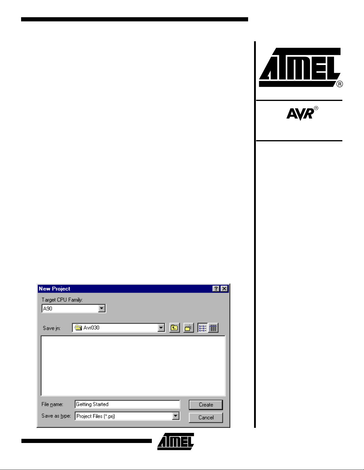
Figure 1. Create the Project File
Preparations
The IAR compiler is shipped with a hardware lock dongle. This dongle must b e
connected to the parallel port. Before the
dongle can be used, a windows driver
must be installed. Please see the
instructions included with the dongle for
how to install the windows driver.
Creating a New Project
When the preparatio ns are ready , open
the IAR Embedded Workbench. To create a new project, go to the “File” men u
and select “New” and then “Project”. The
dialog box shown in Figure 1 appears. In
this dialog box, first make a folder
“C:\ AVR030” and then type “Getting
Started” in the “File name” window. This
project should be created in the in the
“C:\AVR030” folder.
8-bit
Microcontroller
Application
Note
Rev. 1483A–09/99
1
Page 2
Settings in “Project-> Options”
Before any cod e can be comp iled and li nked, the opt ions
for the compiler and linker must be set up correctly. By
default, it is possible to select two different targets in the
project window. The two selections are target “Release”,
and target “D ebug”. The debug target is normally used
when running the code in a simulator or emulator, while the
release target is normally used when producing a code that
can be executed in a real device. The settings done in the
“Project->Options” menu are individual for both targets.
Thus, it is necess ary to set al l options twice when usin g
both targets. The main difference between the two targets
is the format of the output file.
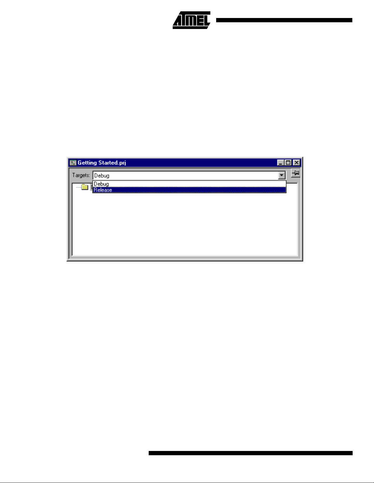
Figure 2. Selecting Target Release
It is also possible to add more targets which options can be
customized to a specific A VR (simulated, emu lated or the
real device). Common and different source files may be
included in the diffe rent targets . A fold er wil l be create d for
each target when linked for the first time.
In this application note, the goal i s to make a file that can
run in the AT90S2313 device. To do this, the release target
will be used. Select the “Release” target in the “Getting
started.prj” window as shown in Figure 2. T hen select the
“Project->Options” menu. The window shown in Figure 3
will pop up.
General Settings
In the “General” category in the “Options” dialog box, the
type of processor used is selected. It is necessary to
change two settings, “Processor Configuration” and “Mem-
ory Model”. Please refer to Table 1 for the correct selection
for these choices for different AVR microcontrollers.
“Memory model tiny” uses a one byt e data pointe r, thus
allowing a maximum of 256 bytes data. “Memory model
2
AVR030
small” uses a two byte data pointer, thus allowing up to 64
Kilobytes data. For the -v0 and -v2 “Proce ssor Configuration only the Memory model tiny” may be used.
In our example, the factory settings should be used, as
shown in Figure 3.
Page 3
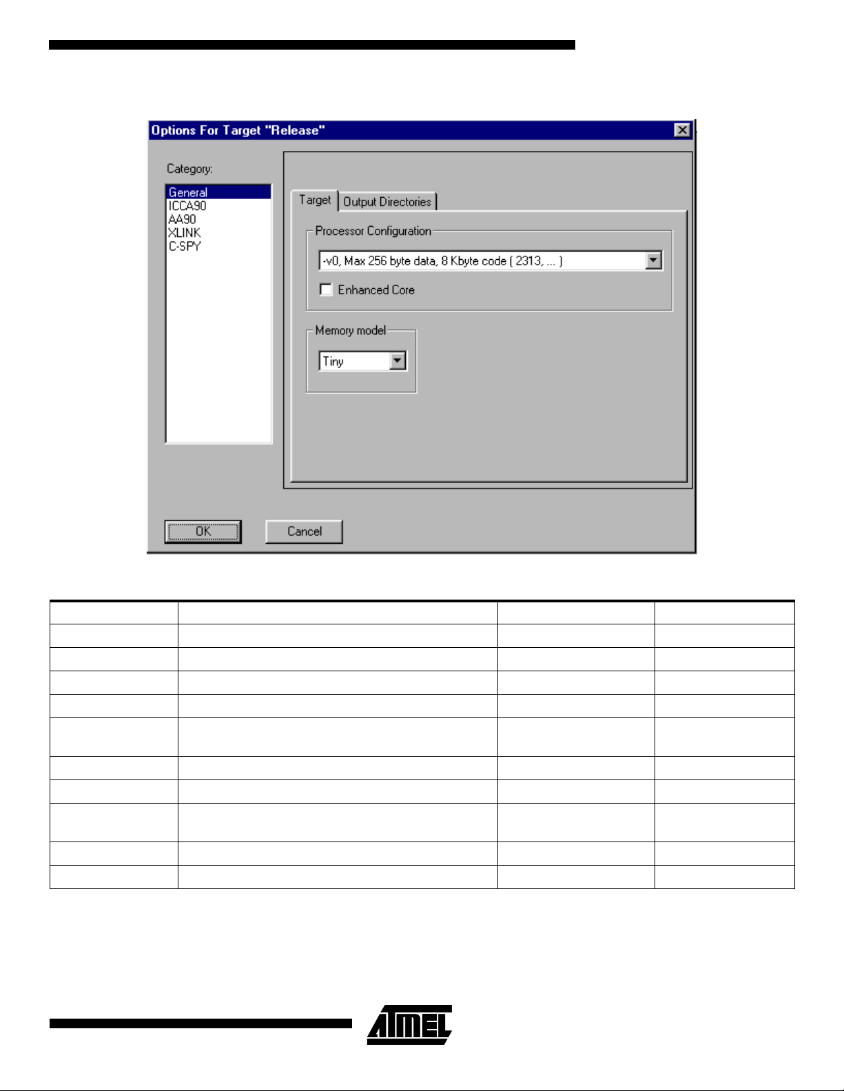
Figure 3. General Options Dialog
AVR030
Table 1. Device Specific Settings
AVR Device Processor Configuration Memory Model XCL file
AT90S2313 V0 (maximum 256 byte data, 8K code) Tiny 2F128S.xcl
AT90S2323 V0 (max 256 byte data, 8K code) Tiny 2F128S.xcl
AT90S2333 V0 (max 256 byte data, 8K code) Tiny 2F128S.xcl
AT90S2343 V0 (max 256 byte data, 8K code) Tiny 2F128S.xcl
AT90S4414 V1 (max 64 Kbyte data, 8K code)
AT90S4433 V0 (max 256 byte data, 8K code) Tiny 4F128S.xcl
AT90S4434 V1 (max 64K byte data, 8K code) Small 4F256S.xcl
AT90S8515 V1 (max 64K ‘byte data, 8K code)
AT90S8534 V1 (max 64K byte data, 8K code) Small 8K256S.xcl
AT90S8535 V1 (max 64K byte data, 8K code) Small 8F512S.xcl
Small
Small
4F256S.xcl
4F64KS.xcl
8F512S.xcl
8F64KS.xcl
3
Page 4

Table 1. Device Specific Settings (Continued)
AVR Device Processor Configuration Memory Model XCL file
ATmega103 V3 (max 64K byte data, 128K code)
ATmega161 V3 (max 64K byte data, 128K code)
ATmega603 V3 (max 64K byte data, 128K code)
ICCA90 Settings
To get the dialog options for the specific settings of the
Compiler, click on the “ICCA90” line in the “Category” tab.
When using the memory model tiny, the factory settings are
OK.
If the memory model small is selected, it is necessary to
check the “Writable strings, constants” checkbox. If this is
not done, vari ables def ined as c onst will not be com piled
correctly. Figure 4 describes the settings when the memory
model small is selected.
The compiler may be optimized for code size or execution
speed. The type and level of optimization may be set in the
“Optimization” group in Figure 4. Only one type of optimiza-
tion may be speci fied fo r a single target . Note t hat if a hig h
level of optimization is used, the user may not be able to
debug the code. The code will be fully debuggable with
Small
Small
Small
128F4KS.xcl
128F64KS.xcl
16F1KS.xcl
16F64KS.xcl
64F4KS.xcl
64F64KS.xcl
optimization level 3 (default for both types of optimization)
or lower.
Also note that it i s strong ly reco mmende d that the “Embed
source” code chec kbox in the “Debu g” tab is checked if a
debugging target, i.e. simulation or emulation, is used. This
will let you debug on the assembly level rath er than on th e
C language level. In AVR Studio you wil l also be able to
see exactly which assem bly code is gen erated for the individual C statements.
On the “List” tab, the user is able to determine whether a
listing is generated, and the information included in this listing. The “Insert mnemonics” option will, i f checked, cause
the compiler to inc lud e th e ge ner ate d as sembly lines in the
listing.
4
AVR030
Page 5

Figure 4. ICCA90 Option Settings
AVR030
AA90 Settings
In the AA90 settings, the options for the assembler can be
changed. Since this application note does not contain any
parts written in assembly, the default settings can be left
unchanged.
XLINK Settings
The linker settin gs give s th e linke r ins truct ions f or ho w to
link together the object codes from the different Compiler,
Assembler and Library modules.
The first thing that needs to be selected is the format of the
output-file the linker is to create. In this application note, the
intention is to generate an “Intel Extended HEX” file which
is recognized by the STK200 starter kit.
5
Page 6

Figure 5. Selecting Output Format
This is done by selecting the “Output” tab of the “XLINK”
options, and click “Other” in the format session. Select
“Intel-extended” from th e output format pul l-down m enu as
shown in Figure 5. When a debugging target is used, it is
normal to select eithe r “Debu g inf o” or “Debug info with terminal I/O”. “Deb ug info wi th termi nal I/O” should be used
when simulating or emulating in AVR Studio.
In the “Output” file group it is possible to rename the outputfile. The default name is the same as the project name.
The other thing that has to be cha nged is the “Link er Co mmand File” us ed. To change this, click the “Include” tab,
and in the “XCL file name” bar, click “Override Default” as
shown in Figure 6. Then cli ck the “...” button, and navigate
to the “2F128S.xcl” file attached to this application n ote.
Here, it is assumed that the file is stored in the
“C:\AVR030” folder. If other de vices t han the AT90S231 3
are used, select t he c or resp ondi ng “XCL” file f ro m Ta ble 1.
For the devices in Table 1 with possibility to have external
RAM, there a re lis ted two possib le “XCL” files in Table 1.
One when using internal RAM only, and one when using
external RAM
6
AVR030
Page 7

Figure 6. Selecting the XCL File
AVR030
The main purpose of the Linker Command File is to define
the code and data segments, which is done in the -Z command. Note that the size of the Dat a Stack an d the Retu rn
Stack is specifi ed ex pli c itl y and may b e c han ged according
to a specific project. The “Linker Command File” will probably need to be edited for each project. “The Linker
Writing the Source File
When the “Project” options are properly configured, the
next step is to wri te the source co de. Th is appli catio n note
uses a simp le prog ram t hat in crem ents PO RTB on whic h
the eight LED s are attac hed. An 8-bit time r is used to ge nerate a dela y betw een i ncrem entat ions , mak ing it p ossib le
to see the LEDs flashing.
Program Listing for AT90S2313
#include <io2313.h>
void initialization(void);
void delay(void);
void initialization(void)
Command Files” attached to this application note must be
considered as a starting point only. Please see the application note AVR032: Li nker Command Files for th e IAR
ICCA90 Compiler for how to mod ify the Linker Comm and
File to fit the specific project.
To open a new source file, select “File->New” and then
select “Source/Text”. In the new windo w that appears, type
in the text below, and sav e it as “AVR030.C” by selectin g
“Save As” in the “File” menu. Make sure to save the file in
the “C:\AVR030” folder.
7
Page 8

{
DDRB = 0xff; // Set PORTB as output
TCCR0 = 0x05; // Count clock/1024.
}
void delay(void) //Producing a delay of 65 ms at 4 MHz
{
while (!(TIFR&0x02)); // Waiting for timer0 overflow flag to be set
TIFR = 0x02; // Clearing overflow flag
}
void main (void)
{
initialization(); //Initialize Pheripherals
while (1) //Forever
{
PORTB++; //Increment PORTB
delay(); //Short delay
}
}
The program is divided into three parts; initialization, delay
and main-loop. In the initialization part, PORTB is set as
output, and TIMER0 starts to count the main clock divided
by 1024.
In the delay subroutine, the c ontrol le r waits for the TIME R0
overflow flag to be set, then clears the flag and exits.
In the main-l oop, the content in PO RTB is incremen ted,
and a delay is called to make the change on PORTB
visible.
8
AVR030
Page 9

Including the Source File in the Project
AVR030
When the source code is written, it has to be included in the
project. This is done by selecting “Files” fr om the “Project”
menu. The dialog box shown in Figure 7 appears. Navigate
Figure 7. Selecting Source-files
to the “C:\AVR030” fo lder, select the file “AVR030.C” by
clicking on it, and select “Add”. Click “Done” to exit the dialog box.
Compiling the Code
To compile the code, select “Project -> Make” or pr ess
“F9”. If everything is don e correc tly, the code co mpile s and
links with no errors, and an exec utab le HE X co de is pla ce d
in the file “C:\AVR030\RELEASE\EXE\GETTING
STARTED.A90”.
Loading the File Into the STK200 Starter Kit
To run the code, the file has to be programmed into an
AT90S2313. This application note describes how to load it
to an AT90S2313 in the STK200 starter kit.
The software used by the STK200 is called AVR ISP. The
STK200 dongle must be mounted on the parallel port.
When this is done, a new project can be opened.
A new project is opened by selecting “Project->New
Project” in AVR ISP. Highlight the AT90S2313 from the
device selection menu and click “OK”.
In the “Project Manager” window information about the
project can be typed in, and fuse and lock-bit options can
be set. This is not necessary for this project.
The next step is to load the hex-file into the “Program Memory” window. To do this , acti vat e thi s win dow b y cli c king on
the title frame of the window. Now go to the “File” men u
and select “Load”. In the dialog bo x that appe ars, navigat e
to the “AVR030\RELEASE\EXE” folder, and select the
“Getting Started.a90” file.
9
Page 10

To load the program in to the AT90S2 313 on the starter kit,
select the “Program->Auto-Program” option. In t he “Auto-
Program” dialog box, tag “Reload Files”, Erase device and
Program device. Now click “OK”, and the LEDs on the
starter kit should be counting.
Short Reference
Preparations:
-Install dongle driver
-Create destination folder
Getting Started:
1. File->New->Project
2. Project name and path
3. Highlight release folder in project window
4. Project->Options
5. In the General options, select Processor Configuration and Memory Model according to Table 1
6. In the ICCA90 options, tag “Writable strings, constants” if the Memory Model is small, leave
unchanged if Memory Model is tiny
7. In the XLINK options, select output format “Intel
Extended”
8. In the include-tab of the XLINK options, go to the
“XCL file name” bar and select “Override default”.
Select the XCL-file corresponding to your device
from Table 1
9. Write the source code
10. Add the Source file to the project by selecting
“Project->files” and select the file just written
11. Compile by selecting “Project->make” or by pressing “F9”
12. Open AVR ISP and download the hex-file located in
the “avr030\release\exe” folder into the device
10
AVR030
Page 11

Atmel Headquarters Atmel Operations
Corporate Headquarters
2325 Orchard Parkway
San Jose, CA 95131
TEL (408) 441- 0311
FAX (408) 487-2600
Europe
Atmel U.K., Ltd.
Coliseum Business Centre
Riverside Way
Camberley, Surrey GU15 3YL
England
TEL (44) 1276-686-677
FAX (44) 1276-686-697
Asia
Atmel Asia, Ltd.
Room 1219
Chinachem Golden Plaza
77 Mody Road Tsimhatsui
East Kowloon
Hong Kong
TEL (852) 2721- 9778
FAX (852) 2722-1369
Japan
Atmel Japan K.K.
9F, Tonetsu Shinkawa Bldg.
1-24-8 Shinka wa
Chuo-ku, Tokyo 104-0033
Japan
TEL (81) 3-3523-3551
FAX (81) 3-3523-7581
Atmel Colorado Springs
1150 E. Cheyenne Mtn. Blvd.
Colorado Springs, CO 80906
TEL (719) 576-3300
FAX (719) 540-1759
Atmel Rousset
Zone Indus triel le
13106 Rousset Cedex
France
TEL (33) 4-4253-6000
FAX (33) 4-4253-6001
Fax-on-Demand
North America:
1-(800) 292-8635
International:
1-(408) 441-0732
e-mail
literature@atmel.com
Web Site
http://www.atmel.com
BBS
1-(408) 436-4309
© Atmel Corporation 1999.
Atmel Corporation makes no warranty for the use of its products, other than those expressly contained in the Company’s standard warranty which is detailed in Atmel’s Terms and Conditions located on the Company’s web site. The Company assumes no responsibility for
any errors which may appear in this document, reserves the right to change devices or specifications detailed herein at any time without
notice, and does not make any commitment to update the information contained herein. No licenses to patents or other intellectual property of Atmel are granted by the Company in connection with the sale of Atmel products, expressly or by implication. Atmel’s products are
not authorized for use as critical components in life support devices or systems.
Marks bearing ® and/or ™ are registered trademarks and trademarks of Atmel Corporation.
Terms and product names in this document may be trademarks of others.
Printed on recycled paper.
1483A–09/99/xM
 Loading...