


Features
• High-performance, Low-power AVR 8/16-bit XMEGA Microcontroller
• Non-volatile Program and Data Memories
– 16K/32K/64K/128K Bytes of In-System Self-Programmable Flash
– 4K/4K/4K/4K Boot Code Section with Independent Lock Bits
– 1K/2K/2K/2K Bytes EEPROM
– 2K/4K/4K/8K Bytes Internal SRAM
• Peripheral Features
– Four-channel DMA Controller with support for external requests
– Five 16-bit Timer/Counters
3 Timer/Counters with 4 Output Compare or Input Capture channels
2 Timer/Counters with 2 Output Compare or Input Capture channels
High Resolution Extensions on all Timer/Counters
Advanced Waveform Extension on 1 Timer/Counter
– Five USARTs
IrDA Extension on one USART
– TwoTwo-Wire Interfaces (I
– Two SPIs (Serial Peripheral Interfaces)
– AES and DES Crypto Engine
– 16-bit Real Time Counter with Separate Oscillator
– One 12-channel, 12-bit, 2 Msps ADCs
– One 2-channel, 12-bit, 1 Msps DACs
– Two Analog Comparators
– External Interrupts on all General Purpose I/O pins
– Programmable Watchdog Timer with Separate On-chip Oscillator
• Special Microcontroller Features
– Power -on Reset and Pr ogrammab le Brown-out Detection
– Internal and External Clock Options with PLL
– Programmable Multi-level Interrupt Controller
– Sleep Modes: Idle, Power-down, Standby, Power-save, Extended Standby
– Advanced Programming, Test and Debugging Interfaces
PDI (Program and Debug Interface) for programming, test and debugging
• I/O and Pac kages
– 36 Programmable I/O Lines
– 44-lead TQFP
– 44-pad MLF
• Operating Voltage
– 1.8 – 3.6V
• Speed performance
– 0 – 12 MHz @ 1.8 – 2.7V
– 0 – 32 MHz @ 2.7 – 3.6V
2
C and SMBus compliant)
8/16-bit
XMEGA
Microcontroller
ATxmega64A4
ATxmega32A4
ATxmega16A4
ATxmega128A4
Advance
Information
Typical Applications
• Industrial control • Climate control • Hand-held battery applications
• Factory automation • ZigBee • Power tools
• Building control • Motor control • HVAC
• Board control • Networking • Metering
• White Goods • Optical • Medical Application
8069A–AVR–02/08
ATxmega A4
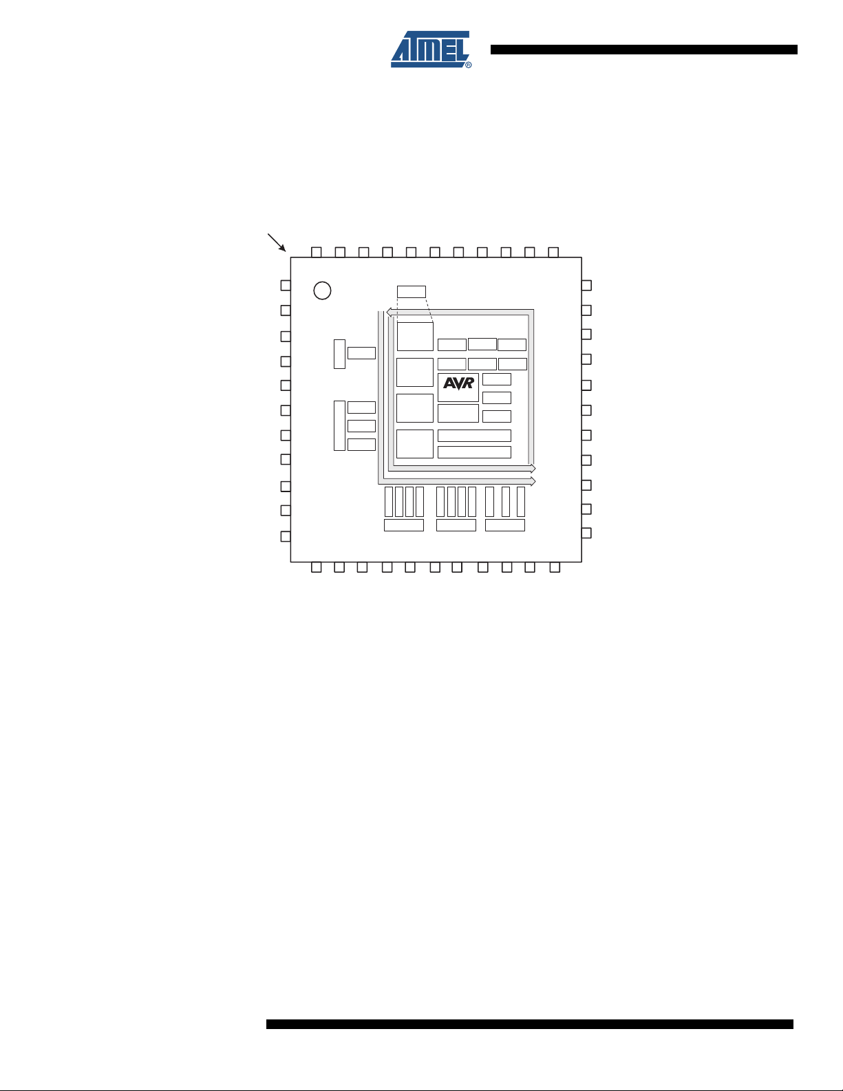
1. Block Diagram/Pinout
INDEX CORNER
AC5/ADC5/PA5
AC6/ADC6/PA6
AC7/ADC7/PA7
AREF/ADC8/PB0
ADC9/PB1
DAC0/ADC10/PB2
DACB1/ADC11/PB3
GND
VCC
SDA/OC0A/_OC0A/PC0
SCL/XCK0/OC0B/OC0A/PC1
1
2
3
4
5
6
7
8
9
10
11
PA4/ADC4/AC4
44
12
PA3/ADC3/AC3
PA2/ADC2/AC2
PA1/ADC1/AC1
PA0/ADC0/AC0/AREF
AVCC
GND
PR1/XTAL1/TOSC1
PR0/XTAL2/TOSC2
PDI_CLK/_RESET
PDI_DATA/TEST
43
42
41
40
39
38
37
36
35
34
33
Port R
DATA BU S
OSC/CLK
Control
BOD POR
TEMP
CPU
DMA
Interrupt Controller
Event System ctrl
DATA BU S
T/C0:1
USART0:1
TWI
Port D
17
18
GND
VREF
RTC
SPI
FLASH
RAM
E2PROM
T/C0:1
Port E
19
VCC
OCD
USART0:1
20
TWI
21
A
ADC A
Port
A
DAC B
B
AC B0
Port
AC B1
13
14
T/C0:1
Port C
15
Power
Control
Reset
Control
Watchdog
USART0:1
TWI
16
EVENT ROUTING NETWORK
SPI
PE3/OC0D/TXD0
32
PE2/OC0C/RXD0
31
VCC
30
GND
29
PE1/OC0B/XCK0/SCL
28
PE0/OC0A/SDA
27
PD7SCK/TXD1
26
PD6MISO/RXD1
25
PD5OC1B/MOSI/XCK1
24
PD4OC1A/_SS
23
PD3/OC0D/TXD0
22
OC0A/PD0
XCK/OC0B/PD1
RXD0/OC0C/PD2
_SS/OC1A/OC0C/PC4
TXD0/OC0D/OC0B/PC3
RXD0/OC0C/_OC0B/PC2
TXD1/SCK/OC0D/PC7
RXD1/MISO/_OC0D/PC6
XCK1/MOSI/OC1B/OC0C/PC5
2
8069A–AVR–02/08
ATxmega A4
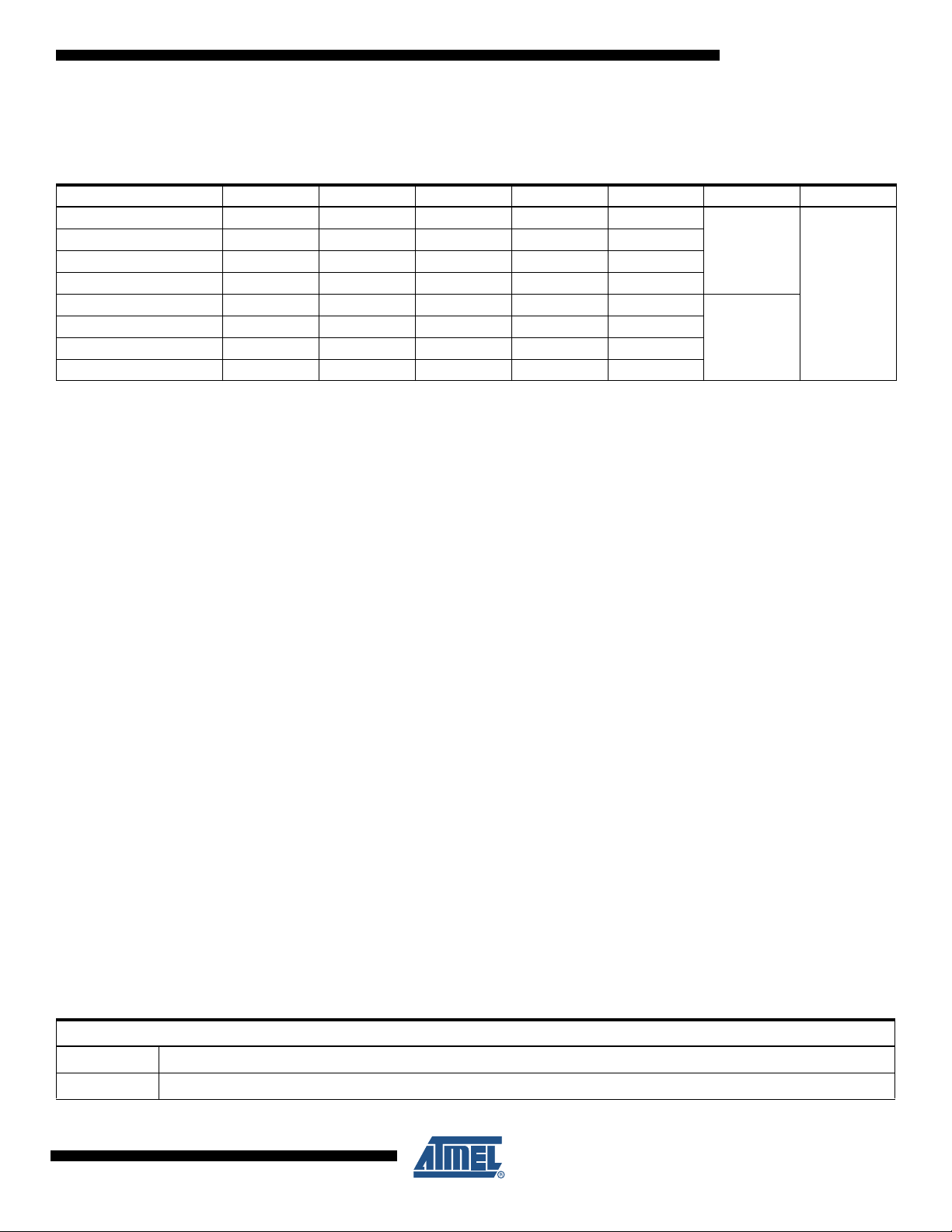
2. Ordering Information
For packaging information, see ”Packaging information” on page 49.
44A
44M1
(1)(2)
Temp
-40° - 85°
Ordering Code Flash (B) E2 (B) SRAM (B) Speed (MHz) Power Supply Package
ATxmega128A4-AU 128K + 4K 2K 8K 32 1.8 - 3.6V
ATxmega64A4-AU 64K + 4K 2K 4K 32 1.8 - 3.6V
ATxmega32A4-AU 32K + 4K 2K 4K 32 1.8 - 3.6V
ATxmega16A4-AU 16K + 4K 1K 2K 32 1.8 - 3.6V
ATxmega128A4-MU 128K + 4K 2K 8K 32 1.8 - 3.6V
ATxmega64A4-MU 64K + 4K 2K 4K 32 1.8 - 3.6V
ATxmega32A4-MU 32K + 4K 2K 4K 32 1.8 - 3.6V
ATxmega16A4-MU 16K + 4K 1K 2K 32 1.8 - 3.6V
Note: 1. This device can also be supplied in waf er form. Please contact your local Atmel sales office for detailed ordering information.
2. Pb-free packaging, complies to the European Directive for Restriction of Hazardous Substances (RoHS directive). Also
Halide free and fully Green.
44A
44M1
8069A–AVR–02/08
Package Type
44-lead, 10 x 10 mm Body Size, 1.0 mm Body Thickness, 0.8 mm Lead Pitch, Thin Profile Plastic Quad Flat Package (TQFP)
44-pad, 7 x 7 x 1.0 mm Body, Lead Pitch 0.50 mm, 5.20 mm Exposed Pad, Micro Lead Frame Package (MLF)
3

ATxmega A4
3. Disclaimer
4. Overview
Typical values contained in this datasheet are based on simulations and characterization of
other AVR microcontrollers manufactured o n th e same proce ss te ch nolo gy. Min a nd Ma x valu es
will be available after the device is characterized.
The XMEGA A4 is a family of low power, high performance and peripheral rich CMOS 8/16-bit
microcontrollers based on the AVR
instructions in a single clock cycle, the XMEGA A4 achieves throughputs approaching 1 MIPS
per MHz allowing the system designer to optimize power co nsumption versus pr ocessing speed.
5. Resources
A comprehensive set of development tools, application notes, and datasheets are available for
download on http://www.atmel.com.
5.1 Recommended reading
• XMEGA A Manual
• Application Notes
This document contains part specific information only. The XMEGA A Manual describes the
peripherals in-depth. The application notes contains example code and show applied use of the
peripherals.
®
enhanced RISC architecture. By executing powerful
4
8069A–AVR–02/08
6. AVR CPU
6.1 Features
6.2 Overview
ATxmega A4
• 8/16-bit high performance AVR RISC Architecture
– 139 instructions
– Hardware multiplier
• 32x8-bit registers directly connected to the ALU
• Stack in RAM
• Stack Pointer accessible in I/O memory space
• Direct addressing of up to 16M bytes of program and data memory.
• True 16/24-bit access to 16/24-bit I/O registers
• Support for 8-, 16- and 32-bit Aritmetic’s
• Configuration Change Protection of system critical features.
The XMEGA A4 uses an 8/16-bit AVR CPU. The main function of the CPU is to ensure correct
program execution. The CPU must therefore be able to access memories, perform calculations
and control peripherals. Interrupt h andling is de scribed in a separat e section. Figure 6-1 on page
5 shows the CPU block diagram.
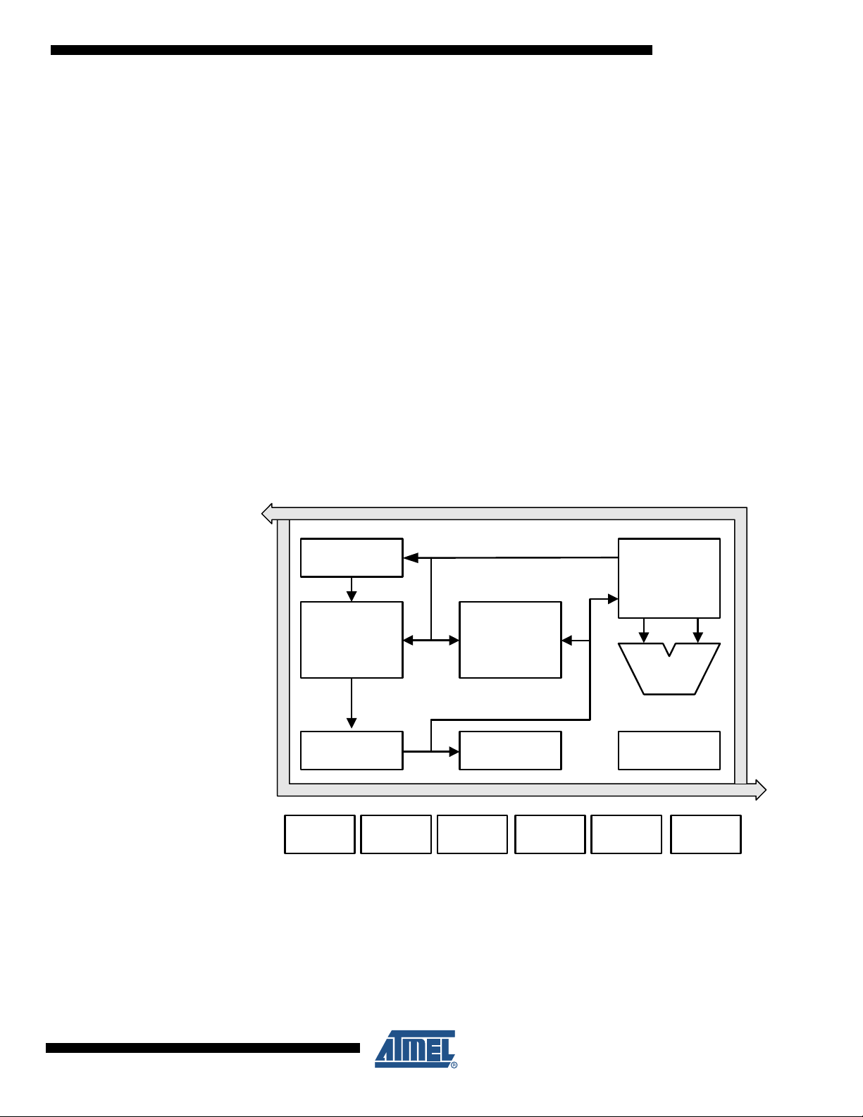
Figure 6-1. CPU block diagram
DATA BUS
Program
Counter
Indirect Addressing
32 x 8
General
Purpose
Registers
FLASH
Program
Memory
SRAM
Data
ALU
Direct Addressing
Instruction
Register
I/O
MODULE 1
I/O
MODULE n
The AVR uses a Harvard architecture - with separate memories and buses for program and
data. Instructions in the program memory are executed with a single level pipeline. While one
instruction is being executed, the next instruction is pre-fetched from the program memory. This
concept enables instructions to be executed in every clock cycle. The pr ogram memory is InSystem Re-programmable Flash mem o ry.
Instruction
Decoder
I/O
MODULE n
DATA BUS
EEPROMI/O LINES
STATUS/
CONTROL
PMIC
8069A–AVR–02/08
5

ATxmega A4
6.3 Register File
The fast-access Register File contains 32 x 8-bit general purpose working registers with a single
clock cycle access time. This allows single-cycle Arithmetic Logic Unit (ALU) operation. In a typical ALU operation, two operands are output from the Register File, the operation is executed,
and the result is stored back in the Register File - in one clock cycle.
Six of the 32 registers can be used as three 16-bit indirect address register pointers for Data
Space addressing - enabling efficient address calculations. One of these add ress pointers can
also be used as an address pointer for look up tables in Flash program memory.
6.4 ALU - Arithmetic Logic Unit
The high performance Arithmetic Logic Unit (ALU) supports arithmetic and logic operations
between registers or between a constant and a register. Single register operations can also be
executed in the ALU. Within a single clock cycle, arithmetic operations between genera l purpose
registers or between a register and an immediate are executed. Aft er an arithmetic or logic operation, the Status Register is updated to reflect information about the result of the operation.
The ALU operations are divided into three main categories – arithmetic, logical, and bit-functions. Both 8-, 16 and 32-bit arithmet ic is supp orted. Th e ALU als o provide a powerfu l multiplier
supporting both signed/unsigned multiplication and fractional format.
6.5 Program Flow
Program flow is provided by conditional and unconditional jump and call instructions, able to
address the whole address space directly. Most AVR instructions use a 16-bit word format.
Some instructions also use a 32-bit format.
The Program Flash memory space is divided in two sections, the Boot section and the Application section. Both sections have dedicated Lock bits for write and read/write protection. The
Store Program Memory (SPM) instruction used to access the Application section must reside in
the Boot section.
A third section exists inside the Application section. This section, the Application Table section,
has separate Lock bits for write and read/write protection. The Application Table section can be
used for storing non-volatile data or application software.
The Program Counter (PC) addresses t he locat ion fr om wh ere t he instru ction s are f etched . Af ter
a reset, the PC is set to location ‘0’.
During interrupts and subroutine calls, the return address PC is stored on the Stack. The Stack
is effectively allocated in the general data SRAM, and consequent ly the Stack size is o nly limited
by the total SRAM size and the usage of the SRAM. The Stack Pointer (SP) is default reset to
the highest address of the internal SRAM. The SP is read/write accessible in the I/O space. The
data SRAM can easily be accessed through the five dif ferent addr essing modes support ed in the
AVR architecture.
6
8069A–AVR–02/08

7. Memories
7.1 Features
7.2 Overview
ATxmega A4
• Flash Program Memory
– One linear address space
– In-System Reprogrammable
– Self-Programming and Bootloader support
– Application Section fo r ap plication code
– Application Table Section for application code or data storage
– Bootloader Section for application code or bootl oader code
– Separate lock bits and protection for all sections
• Data Memory
– One linear address space
– Single cycle access from CPU
– SRAM
– EEPROM
Byte or page accessible
Optional memory mapping for direct Load/Store
– I/O Memory
Configuration and Status register for all peripherals and modules
16 bit accessible General Purpose Register for global variable or flags
– External Memory
– Bus arbitration
Safe and deterministic handling of CPU and DMA Controller priority
– Separate buses for SRAM, EEPROM, IO Memory and External Memory access
• Enables simulatiouns bus access for CPU and DMA Controller
The AVR architecture has two main memory spaces, the Program Memory and the Data Memory. In addition, the XMEGA A4 features an EEPROM Memory for non-volatile data storage. All
three memory spaces are linear and require no pagi ng. The memory conf igurations are shown in
”Ordering Information” on page 3.
Non-volatile memory spaces can be locked for further write and read/write operations. This prevents unrestricted access to the application software.
7.3 In-system Programmable Flash Program Memory
The XMEGA A4 contains On-chip In-System Re-programmable Flash memory for program storage, see Table 7-1 on page 8. Since all AVR instructions are 16- or 32-bits wide, each Flash
address location is 16 bits.
The XMEGA A4 has additional Boot section for bootloader applications. The Store Program
Memory (SPM) instruction used to write to the Flash will only operate from this section. Operation of the SPM is also associated with Boot Lock bits for software protection.
The XMEGA A4 has an Application Table section inside the Application section for storage of
Non-volatile data.
8069A–AVR–02/08
7
ATxmega A4
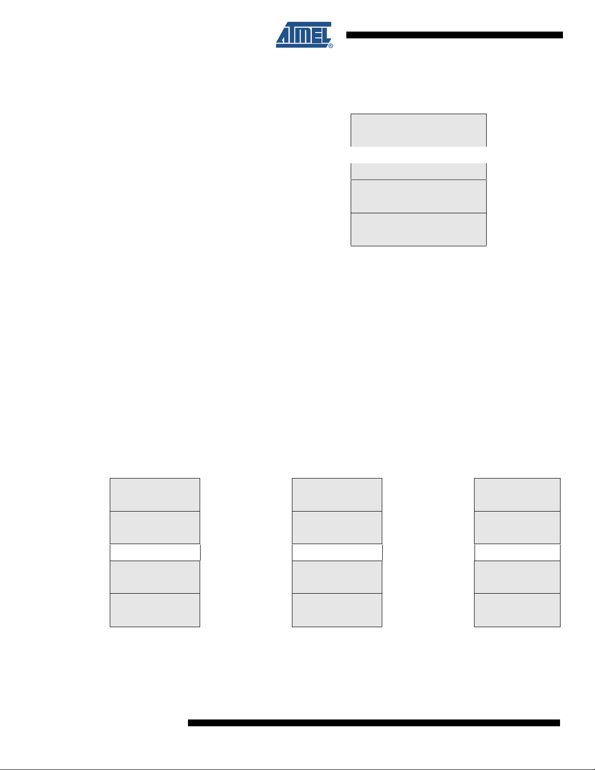
Figure 7-1. Flash Program Memory (Hexadecimal address)
Word Address
EFFF / 77FF / 37FF / 17FF
F000 / 7800 / 3800 / 1800
FFFF / 7FFF / 3FFF / 1FFF
10000 / 8000 / 4000 / 2000
10FFF / 87FF / 47FF / 27FF
The Application Table- and Boot sections can also be used for general application software.
7.4 SRAM Data Memory
The XMEGA A4 has internal SRAM memory for data storage. The Memory Map for the devices
in the family resemble each other, see Table 7-2 on page 8.
7.5 EEPROM Data Memory
The XMEGA A4 has internal EEPROM memory for non-volatile data storage. It is addressable
either in a separate data space or it can be memory mapped the normal data space. The
EEPROM memory supports both byte and page access.
The Internal SRAM and EEPROM memory spaces start at the same address in all devices, see
Table 7-2 on page 8. The Reserved memory space is empty.
0
Application Section
(128K/64K/32K/16K)
...
Application Table Section
(4K/4K/4K/4K)
Boot Section
(4K/4K/4K/4K)
Figure 7-2. Data Memory Map (Hexadecimal address)
Byte Address ATxmega64A4 Byte Address A Txmega32A4 Byte Address ATxmega16A4
1000
2000
3000
0
I/O Registers
EEPROM
Internal SRAM
External Memory
(0 to 16 MB)
(4KB)
(2K)
(4K)
0
FFF FFF FFF
1000
17FF 17FF 17FF
2000
2FFF 2FFF 27FF
3000
FFFFFF FFFFFF FFFFFF
I/O Registers
(4KB)
EEPROM
(2K)
RESERVED RESERVED RESERVED
Internal SRAM
(4K)
External Memory
(0 to 16 MB)
1000
2000
2800
0
I/O Registers
EEPROM
Internal SRAM
External Memory
(0 to 16 MB)
(4KB)
(1K)
(2K)
8
8069A–AVR–02/08

ATxmega A4
Byte Address ATxmega64A4
7.6 I/O Memory
0
FFF
1000
17FF
2000
3FFF
4000
FFFFFF
I/O Registers
(4KB)
EEPROM
(2K)
RESERVED
Internal SRAM
(8K)
External Memory
(0 to 16 MB)
All XMEGA A4 I/Os and peripherals are addressable through I/O memory locations in the data
memory space. All I/O locations may be accessed by the LD/L DS/LDD and ST/STS/STD
instructions, transferring data between the 32 general purpose registers and the I/O memory.
IN and OUT instructions can address I/O memory locations in the range 0x00 - 0x3F directly.
I/O registers within the address range 0x00 - 0x1F are directly bit-accessible using the SBI and
CBI instructions. The value of single bits can be checked by using th e SBIS and SBIC instructions in these registers.
The I/O space definition of the XMEGA A4 is shown in ”Peripheral Module Address Map” on
page 48.
8069A–AVR–02/08
9

ATxmega A4
8. DMA - Direct Memory Access Controller
8.1 Features
• Allows High-speed data transfer
– From memory to peripheral
– From memory to memory
– From peripheral to memory
– From peripheral to peripheral
• 4 Channels
• From 1 byte and up to 16 M bytes transfers in a single transaction
• Multiple addressing modes for source and destination address
–Incremental
– Decremental
– Static
• 1, 2, 4, or 8 bytes Burst Transfers
• Programmable priority between channels
8.2 Overview
The XMEGA A4 has a Direct Memory Access (DMA) controller to move data between memories
and peripherals in the data space. The DMA controller uses the same data bus as the CPU to
transfer data.
The XMEGA A4 has 4 DMA channels that may be configured independently. The DMA controller supports transfer of up to 64K data blocks and can be configured to access memory with
incrementing, decrementing or static addressing.
Since the DMA can access all the peripherals through the I/O memory, the DMA may be used
for automatic transfer of data to/from communication modules, as well as automatic da ta
retrieval from ADC conversions or data transfer to DAC conversions.
The DMA controller can read from memory mapped EEPROM, but it cannot write to the
EEPROM or access the Flash.
10
8069A–AVR–02/08

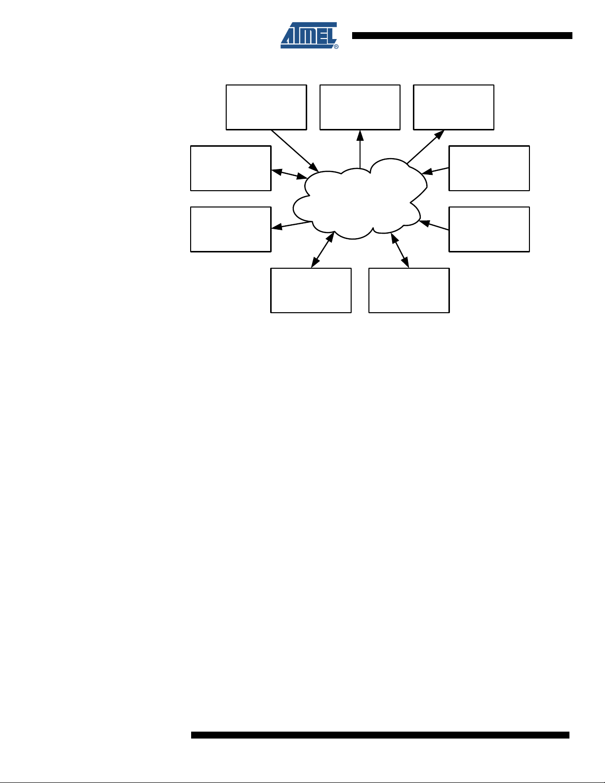
9. Event System
9.1 Features
9.2 Overview
• Inter peripheral communication and signalling
• CPU and DMA independent operation
• 8 Event Channels allows for up to 8 signals to be routed at the same time
• Events can be generated by
– TImer/Counters (TCxn)
– Real Time Counter (RTC)
– Analog to Digital Converters (ADCx)
– Analog Comparators (ACx)
– Ports (PORTx)
– System Clock (Clk
– Software (CPU)
SYS
)
• Events can be used by
– TImer/Counters (TCxn)
– Analog to Digital Converters (ADCx)
– Digital to Analog Converters (DACx)
– Ports (PORTx)
– DMA Controller (DMAC)
• Advanced Features
– Manual Event Generation from software (CPU)
– Quadrature Decoding
– Digital Filtering
• Operative in Active and Idle mode
ATxmega A4
The Event System is a set of features for inter pe ripheral comm unication. It enable s the possibility for a change of state in one peripheral to automatically trigger actions in other pe ripherals.
What change of state in a peripheral that will trigger actions in other peripherals is configurable
in software. It is a simple, but powerful system as it allows for autonomous cont rol of per iph erals
without any use of interrupt, CPU or DMA resources
The indication of a change of state in a peripheral is referred to as an event. The events are
passed between peripherals using a dedicated ro uting network called the Event Routing Net work. Figure 9-1 on page 12 shows a basic block diagram of the Event System with the Event
Routing Network and the peripherals that are connected. The event system is no t a single enti ty,
but a set of features for inter peripheral communication. This highly flexible system can be used
for simple rerouting of signals, pin functions or for sequencing of events.
The Event System is functional in both Active- and Idle mode.
8069A–AVR–02/08
11
ATxmega A4
Figure 9-1. Event System Block Diagram
CPU
ADCx
DACx
PORTxn
The the event routing network can directly connect together ADCs, DACs, Analog Comparators
(AC), I/O ports (PORT), the Real-time Counter (RTC), and Timer/Counters (T/C). Events can
also be generated from software (CPU).
DMA IRCOM
RTC
Event
Routing Network
ACxn
T/Cxn
12
8069A–AVR–02/08

10. System Clock and Clock options
10.1 Features
• Fast start-up time
• Safe run time clock switching
• 4 Internal Oscillators; 32 MHz, 2 MHz, 32 kHz, 32 kHz Ultra Low Power (ULP)
• 0.4 - 16 MHz Crystal Oscillator, 32 kHz Crystal Oscillator, external clock
• PLL with internal and external clock options and 1 to 31x multiplication
• Clock Prescalers with 1 to 2048x division
• Fast peripheral clock.
• Automatic Run-Time Calibration of internal oscillators
• Crystal Oscillator failure detection
10.2 Overview
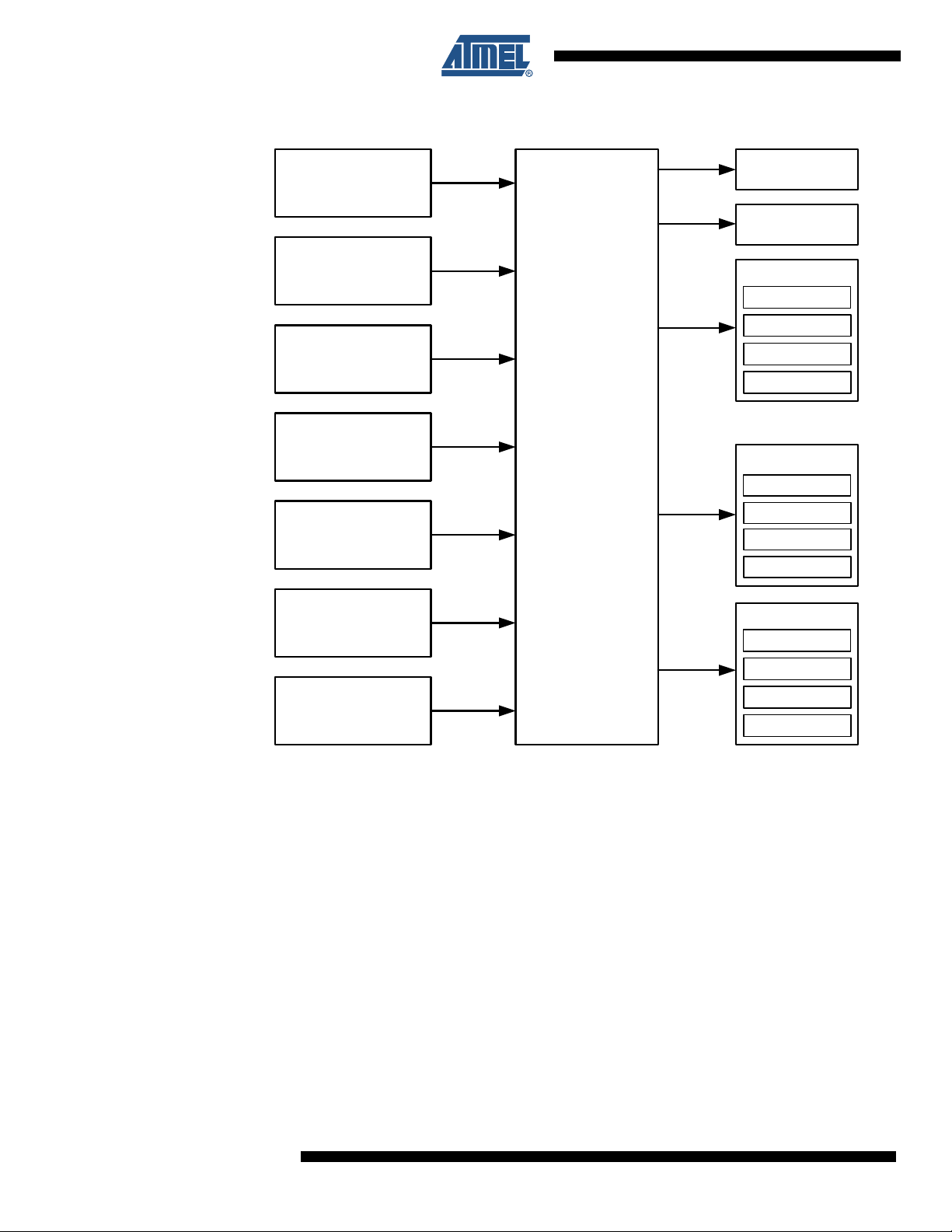
XMEGA A4 has an advanced clock system, supporting a lar ge numbe r of clo ck sources. It in corporates both integrated oscillators, and external crystal oscillators and resonators. A high
frequency Phase Locked Loop (PLL) and clock pr escalers can be controlled from software to
generate a wide range of clock frequencies. The clock distribution also enables the possibility to
switch between clock sources from software during run-time. A calibration feature (DFLL) is
available, and can be used for automatic run-time calibration of the internal oscillators. A Crystal
Oscillator Failure Monitor can be enabled to issue a Non-Maskable Interrupt and switch to internal oscillator if the external oscillator fails. Figure 10-1 on page 14 shows the principal clock
system in XMEGA A4.
ATxmega A4
8069A–AVR–02/08
13
ATxmega A4
Figure 10-1. Clock system overview
32 KHz ULP
Internal Oscillator
32 KHz Calibrated
Internal Oscillator
32 KHz
Crystal Oscillator
0.4 - 16 MHz
Crystal Oscillator
2 MHz
Run-time Calibrated
Internal Oscillator
32 MHz
Run-time Calibrated
Internal Oscillator
CLOCK
CONTROL
UNIT
with PLL
WDT/BOD
RTC
PERIPHERALS
ADC
DAC
...
...
SYSTEM
CPU
DMA
INTERRUPT
...
MEMORY
RAM
External
Clock Input
Each clock source is briefly described in the following sub-sections.
FLASH
EEPROM
...
14
8069A–AVR–02/08

10.3 Clock Options
10.3.1 32 kHz Ultra Low Pow e r Inte rnal Os c ill at or
The 32 kHz Ultra Low Power (ULP) Internal Oscillator is a very low power consumptio n clock
source based on internal components only. As it is intended mainly for system functions, it
should not be used when an accurate clock is required.
10.3.2 32 kHz Calibrated Internal Oscillator
Compared to the internal ULP oscillator, the 32 kHz Calibrated Internal Oscillator is a high accuracy clock source based on internal components only.
10.3.3 32 kHz Crystal Oscillator
The 32 kHz Crystal Oscillator is a low power driver for an external watch crystal.
10.3.4 0.4 - 16 MHz Crystal Oscillator
The 0.4 - 16 MHz Crystal Oscillator is a driver intended both for driving resonators and crystals
from 400 kHz to 16 MHz.
10.3.5 2 MHz Run-time Calibrated Internal Oscillator
ATxmega A4
The 2 MHz Run-time Calibrated Internal Oscillator is a high frequency oscillator based on internal components only. The oscillator can use the 32 kHz Calibrated Internal Oscillator or the 32
kHz Crystal Oscillator to calibrate the frequency run-time to compensate for temperature and
voltage drift, optimizing the accuracy of the oscillator.
10.3.6 32 MHz Run-time Calibrated Internal Oscillator
The 32 MHz Run-time Calibrated Internal Oscillator is a high frequency oscillator based on internal components only. The oscillator can use the 32 kHz Calibrated Internal Oscillator or the 32
kHz Crystal Oscillator to calibrate the frequency run-time to compensate for temperature and
voltage drift, optimizing the accuracy of the oscillator.
10.3.7 External Clock input
The external clock input gives the possibility to connect to a clock from an external source.
10.3.8 PLL with Multiplication factor 2 - 31x
The PLL provides the possibility of multiplying a frequency with any real number from 2 to 31. In
combination with some prescalers, this gives a numerous number of clock frequency options to
use.
8069A–AVR–02/08
15

ATxmega A4
11. Power Management and Sleep Modes
11.1 Features
• 5 sleep modes
–IDLE
– Power-down
–Power-save
–Standby
– Extended standby
• Power Reduction register to disable clock to un u sed peripheral
11.2 Overview
The XMEGA A4 provides various sleep modes tailored to reduce power consumption to a minimum. All sleep modes are accessible from Active mode. In Active mode the CPU is executing
application code. The application code decides when and what sleep mode to enter. Interrupts
from enabled peripherals and all enabled reset sources can restore the microcontroller from
sleep to Active mode. This is called a wake-up
In addition Power Reduction Registers (PRR) provides a method to stop the clock to individual
peripherals from software. When this is done the current state of the peripheral is frozen and
there is no power consumption from the peripheral.
11.3 Sleep Modes
11.3.1 Idle Mode
In Idle mode the CPU and Non-Volatile Memory are stopped, but all peripherals including the
Interrupt Controller, Event System and DMA Controller are kept running.
Interrupt request from all enabled interrupts will wake the device.
11.3.2 Power-down Mode
Power-save mode is identical to Power-down, with one exception:
If the Real Time Counter (RTC) is enabled, it will keep running during sleep and the device can
also wake up from either RTC Overflow or Compare Match interrupt.
11.3.3 Power-save Mode
Power-save mode is identical to Power-down, with one exception:
If the Real Time Counter (RTC) is enabled, it will keep running during sleep and the device can
also wake up from either RTC Overflow or Compare Match interrupt.
11.3.4 Standby Mode
Standby mode is identical to Power-down with the exception that the system clock sources are
kept running, while the CPU, Peripheral and RTC clocks are stopped. This r edu ces t he wake-up
time when external crystals or resonators are used.
16
8069A–AVR–02/08

11.3.5 Extended Standby Mode
Extended Standby mode is identical to Power-save mode with the exception that the system
clock sources are kept running while the CPU and Peripheral clocks are stopped. This reduces
the wake-up time when external crystals or resonators are used.
ATxmega A4
8069A–AVR–02/08
17

ATxmega A4
12. System Control and Reset
12.1 Resetting the AVR
During reset, all I/O Registers are set to their initial values. Application execution starts from the
Reset Vector. The instruction placed at t he Reset Vector should be a JMP - Absolute Jump instruction to the reset handling r outine. If the applic ation neve r enab les an int errupt sour ce, th e
Interrupt Vectors are not used. The regular application code can then be placed at these locations. This is also the case if the Reset Vector is in the Application section while the Interrupt
Vectors are in the Boot section or vice versa.
The I/O ports of the AVR are immediately tri-stated when a reset source goes active.
The reset functionality is asynchronous, hence no running clock is required to reset the device.
12.2 Reset Sources
The reset source can be determined by the application by readig a reset status register. The
XMEGA A4 has the following sources of reset:
•
Power-on Reset
• External Reset
• Watchdog Reset
• Brown-out Reset
• PDI reset
• Software reset
12.2.1 Power-on Re se t
The MCU is reset when the supply voltage VCC is below the Power-on Reset threshold voltage.
12.2.2 External Reset
The MCU is reset when a low level is present on the RESET pin.
12.2.3 Watchdog Reset
The MCU is reset when the Watchdog Timer period exp ires and the Wat chdog Reset is enable d.
12.2.4 Brown-out Reset
The MCU is reset when the supply voltage VCC is below the Brown-out Reset threshold voltage
and the Brown-out Detector is enabled.
12.2.5 PDI reset
The MCU may be reset through the Program and Debug Interface (PDI).
12.2.6 Software reset
The MCU may be reset by the CPU writing to a special I/O register.
18
8069A–AVR–02/08

12.3 WDT - Watchdog Timer
12.3.1 Features
11 selectable timeout period, from 8 ms to 8s.
•
• Two operation modes
– Standard mode
– Window mode
• Runs from 1 kHz Ultra Low Power clock reference
• Configuration lock
12.3.2 Overview
The XMEGA A4 has a Watchdog Timer (WDT) that will run continuously when turned on. If the
Watchdog Timer is not reset within a software configurable time-out period, the microcontroller
will reset. To prevent this reset, a Watchdog Reset (WDR) instruction must be run by software to
reset the WDT.
The WDT has a Window mode. In this mode the WDR instruction must be run within a specified
period called a window. Application software can set the minimum and maximum limits for this
window. If the WDR instruction is not run inside the window limits, the microcontroller will be
reset.
ATxmega A4
For maximum safety, the WDT also has an Always-on mode. This mode is enabled by programming a fuse. In Always-on mode, application software can not disable t he WDT.
A protection mechanism is used to prevent unwante d enabling, disabling or change of WDT
settings.
8069A–AVR–02/08
19

ATxmega A4
13. PMIC - Programmable Multi-level Interrupt Controller
13.1 Features
• Separate interrupt vector for each interrupt
• Short, predictable interrupt response time
• Programmable Multi-level Interrupt Controller
– 3 programmable interrupt levels
– Selectable priority scheme within low level interrupts (round-robin or fixed)
– Non-Maskable Interrupts (NMI)
• Interrupt vectors can be moved to the start of the Boot Section
13.2 Overview
XMEGA A4 has a Programmable Multi-level Interrupt Controller (PMIC). All peripherals can
define three different priority levels for interrupts; high, medium or low. Medium level interrupts
may interrupt low level interrupt service routines. High level interrupts may interrupt both lowand medium level interrupt service routines. Low level interrupts have an optional round robin
scheme to make sure all interrupts are serviced within a certain amount of time.
A Non-Maskable Interrupt (NMI) can detect oscillator failure.
13.3 Interrupt vectors
When an interrupt is serviced, the program counter will jump to the interrupt vector address. The
interrupt vector is the sum of the module or peripherals base address and the specific interrupt's
offset address. The base addresses for the XMEGA A4 device is shown in Table 13-1. Offset
addresses for each interrupt available in the peripheral are described for each peripheral in the
XMEGA A manual. For peripherals or modules that have only one interrupt, the interrupt vector
is shown in Table 13-1. The program address is the word add ress.
Table 13-1. Reset and Interrupt Vectors
Program Address
(Base Address) Source Interrupt Description
0x000 RESET
0x002 IVEC_XOSCF_INT_vect Crystal Oscillator Failure Interrupt vector (NMI)
0x004 IVEC_PORTC_INT_base Port C Interrupt base
0x008 IVEC_PORTR_INT_base Port R Interruptbase
0x00C IVEC_DMAC_INT_base DMA Controller Interrupt base
0x014 IVEC_RTC_INT_base Real Time Counter Interrupt base
0x018 IVEC_TWIC_INT_base Two-Wire Interface on Port C Interrupt base
0x01C IVEC_TIMERC0_INT_base Timer/Counter 0 on port C Interrupt base
0x028 IVEC_TIMERC1_INT_base Timer/Counter 1 on port C Interrupt base
0x030 IVEC_SPIC_INT_vect SPI C Interrupt vector
0x032 IVEC_USARTC0_INT_base USART 0 on port C Interrupt base
0x03D IVEC_USARTC1_INT_base USART 1 on port C Interrupt base
0x03E IVEC_AES_INT_vect AES Interrupt vector
0x040 IVEC_NVM_INT_base Non-Volatile Memory INT base
20
8069A–AVR–02/08

Table 13-1. Reset and Interrupt Vectors (Continued)
Program Address
(Base Address) Source Interrupt Description
0x044 IVEC_PORTB_INT_base Port B INT base
0x04E IVEC_ADCB_INT_base Analog to Digital Converter Port B INT base
0x056 IVEC_PORTE_INT_base Port E INT base
0x05A IVEC_TWIE_INT_base Two-Wire Interface on Port E INT base
0x05E IVEC_TIMERE0_INT_base Timer/Counter 0 on port E Interrupt base
0x074 IVEC_USARTE0_INT_base USART 0 on port E Interrupt base
0x07A IVEC_USARTE1_INT_base USART 1 on port E Interrupt base
0x080 IVEC_PORTD_INT_base Port D INT base
0x084 IVEC_PORTA_INT_base Port A INT base
0x088 IVEC_ACA_INT_base Analog Comparator Port A INT base
0x08E IVEC_ADCA_INT_base Analog to Digital Converter Port A INT base
0x096 IVEC_TWID_INT_base Two-Wire Interface on Port D INT base
0x09A IVEC_TIMERD0_INT_base Timer/Counter 0 on po rt D Interrupt base
0x0A6 IVEC_TIMERD1_INT_base Timer/Counter 1 on po rt D Interrupt base
0x0AE IVEC_SPID_INT_vector SPI D Interrupt vector
ATxmega A4
8069A–AVR–02/08
21

ATxmega A4
14. I/O Ports
14.1 Features
14.2 Overview
• Selectable input and output configuration for each pin indi vidually
• Flexible pin configuration through dedicated Pin Configuration Register
• Synchronous and/or asynchronous input sensing with port interrupts and events
– Sense both edges
– Sense rising edges
– Sense falling edges
– Sense low level
• Asynchronous wake-up signalling
• Highly configurable output driver and pull settings:
– Totem-pole
– Pull-up/-down
– Wired-AND
– Wired-OR
– Bus keeper
– Inverted I/O
• Slew rate control
• Flexible pin masking
• Configuration of multiple pins in a single operation
• Read-Modify-Write (RMW) support
• Toggle/clear/set registers for OUT and DIR registers
• Clock output on port pin
• Event Channel 7 output on port pin
• Mapping of port registers (virtual ports) into bit accessible I/O memory space
The XMEGA A4 has flexible General Purpose I/O (GPIO) Ports. A port consists of up to 8 pins,
ranging from pin 0 to pin 7. The ports implement severa l funct io ns, including inte rrup ts, synchronous/asynchronous input sensing and configurable output settings. All functions are individual
per pin, but several pins may be configured in a single operation.
14.3 I/O configuration
All port pins have programmable output configuration. In addition, all GPIO pins have inverted
I/O. For an input, this means inverting the signal between the port pin and the pin register. For
an output, this means inverting the output signal between the port register and the port pin.
Some port pins also have configurable slew rate limitation to reduce electromagnetic emission.
22
8069A–AVR–02/08

14.3.1 Push-pull
ATxmega A4
Figure 14-1. I/O configuration - Totem-pole
DIRn
14.3.2 Pull-down
14.3.3 Pull-up
OUTn
INn
Figure 14-2. I/O configuration - Totem-pole with pull-down (on input)
DIRn
OUTn
INn
Figure 14-3. I/O configuration - Totem-pole with pull-up (on input)
Pn
Pn
14.3.4 Bus-keeper
8069A–AVR–02/08
DIRn
OUTn
Pn
INn
The bus-keeper’s weak output produces the same logical level as the last output level. It acts as
a pull-up if the last level was ‘1’, and pull-down if the last level was ‘0’.
23

ATxmega A4
Figure 14-4. I/O configuration - Totem-pole with bus-keeper
DIRn
14.3.5 Others
OUTn
INn
Figure 14-5. Output configuration - Wired-OR with optional pull-down
OUTn
INn
Figure 14-6. I/O configuration - Wired-AND with optional pull-up
Pn
Pn
24
INn
Pn
OUTn
8069A–AVR–02/08

14.4 Input sensing
ATxmega A4
• Sense both edges
• Sense rising edges
• Sense falling edges
• Sense low level
The basic input sensing may be synchronous or asynchronous and is built on the configuration
shown in Figure 14-7 on page 25.
Figure 14-7. Input sensing system overview
Asynchronous sensing
14.5 Port Interrupt
Pn
INVERTED I/O
Synchronizer
INn
Q
Q
D
D
R
R
EDGE
DETECT
Synchronous sensing
EDGE
DETECT
Interrupt
Control
IREQ
Event
In addition, all GPIO pins may be configured as inverted I/O, meaning that the pin value is
inverted before sensing.
Ports can have pin-change interrupts an d external interrupts. Each po rt supports being the
source of two interrupts, and each pin may be configured individually or grouped. Each of the
interrupts may be given a specific priority and given specific sense configuration.
8069A–AVR–02/08
25

ATxmega A4
15. T/C - 16-bits Timer/Counter with PWM
15.1 Features
• 3 Timer/Counter 0 (Timer0)
• 2 Timer/Counter 1 (Timer1)
• T rue 16-bit Design
• Double Buffered Timer Period Setting
• Compare or Capture Channels are Double Buffered
• 4 Combined Compare or Capture (CC) Channels in Timer0
• 2 Combined Compare or Capture (CC) Channels in Timer1
• Waveform Generation:
– Single Slope Pulse Width Modulation
– Dual Slope Pulse Width Modulation
– Frequency Generation
• Input Capture:
– Input Capture with Noise Cancelling
– Frequency Capture
– Pulse width capture
– 32-bit input capture
• Event Counter with Direction Control
• Timer Overflow and Timer Error Interrupts and Events
• One Compare Match or Capture Interrupt and Event per CC Channel
• Supports DMA Operation
• Hi-Resolution Extension (Hi-Res)
• Advanced Waveform Extension (AWEX)
15.2 Overview
XMEGA A4 has 5 Timer/Counters. 3 are of type Timer0 and 2 of type Timer1. The difference
between Timer0 and Timer1 type is that Timer0 has 4 Compare/Capture channels, and Timer1
only has 2. In addition, Timer0 may have an Advanced Waveform extension (AWEX), that is not
available in Timer1.
The Timer/Counters (T/C) are 16-bit wide and can count any clock, event or input signal in the
microcontroller. A programmable prescaler is available to get a useful T/C reso lution. Upd ates of
Timer and Compare registers are double buffered to ensure glitch free operation. Using Compare channels many different waveforms can be genera ted, single slope PWM, du al slope PWM
and frequency generation.
The Hi-Resolution Extension can be enabled to increase the waveform generation resolution by
2 bits (4x). This is available for all Timer/Counters.
The Input Capture has a noise canceller to avoid incorrect ca pture of the T/C. Any input pin or
event in the microcontroller can be used to trigger the capture.
A wide range of interrupt or event sources are availa ble, including T/C overflow, Compa re match
and Capture for each timer and CC channel.
PORTC and PORTD each has one Timer/Counter 0 and one Timer/Counter 1. PORTE has one
Timer/Counter 0. Notation of these timers are TCC0, TCC1, TCD0, TCD1, and TCE0.
26
8069A–AVR–02/08

16. AWEX - Advanced Waveform Extension
16.0.1 Features
4-DTI Units (8-pin)
•
• 8-bit Resolution
• Separate High and Low Side Dead-Time Setting
• Double Buffered Dead-Time
• Fault Protection (Event Controlled)
• Single Channel Multiple Output Operation (for BLDC control)
• Double Buffered Pattern Generation
16.1 Overview
The Advanced Waveform Extention (AWEX) provides extra features to the Time/Counter in
Waveform Generation (WG) modes. AWEX enables easy and robust implementation of for
example advanced motor control (AC, BLDC, SR, and Stepper) and power control applications.
Any WG output from the Timer/Counte r 0 are split into a complimentary pair of ou tputs when a ny
AWEX feature is enabled. These output pairs go through a Dead-Time Inse rtion (DTI) unit that
enables generation of the non-inverted Low Side (LS) and inverted High Side (HS) of the WG
output with dead time insertion between LS and HS switching. The DTI outp ut will override the
normal port value according to the port override setting. Optionally the final output can be
inverted by using inverted I/O (INVEN) bit setting for port pin (Pxn).
ATxmega A4
The Pattern Generation unit can be used to generate a synchronized bit pattern on the port it is
connected to. In addition, the waveform generator output from the Compare Channel A can be
distributed to and override all the port pins. When the Pattern generator unit is enabled the DTI
unit i bypassed.
The Fault Protection unit is connected to the Event System, enabling any event to trigger a fault
condition that will disable the AWEX output.
The AWEX is only available on TCC0 and TCE0. The notation of these are AWEXC and
AWEXE.
8069A–AVR–02/08
27
ATxmega A4
17. RTC - Real-Time Counter
17.1 Features
• 16-bit Timer
• Flexible Tick resolution ranging from 1 Hz to 32 kHz
• 1 Compare register
• 1 T op Value register
• Clear timer on Overflow or Compare Match
• Overflow or Compare Match event and interrupt generation
17.2 Overview
The XMEGA A4 includes a 16-bit Real-time Counter (RTC). The RTC can be clocked from a
accurate 32.768 kHz Crystal Oscillator, the 32 kHz Calibrated Internal Oscillator, or from the 32
kHz Ultra Low Power Internal Oscillator. The RTC include both a Period and Compare register,
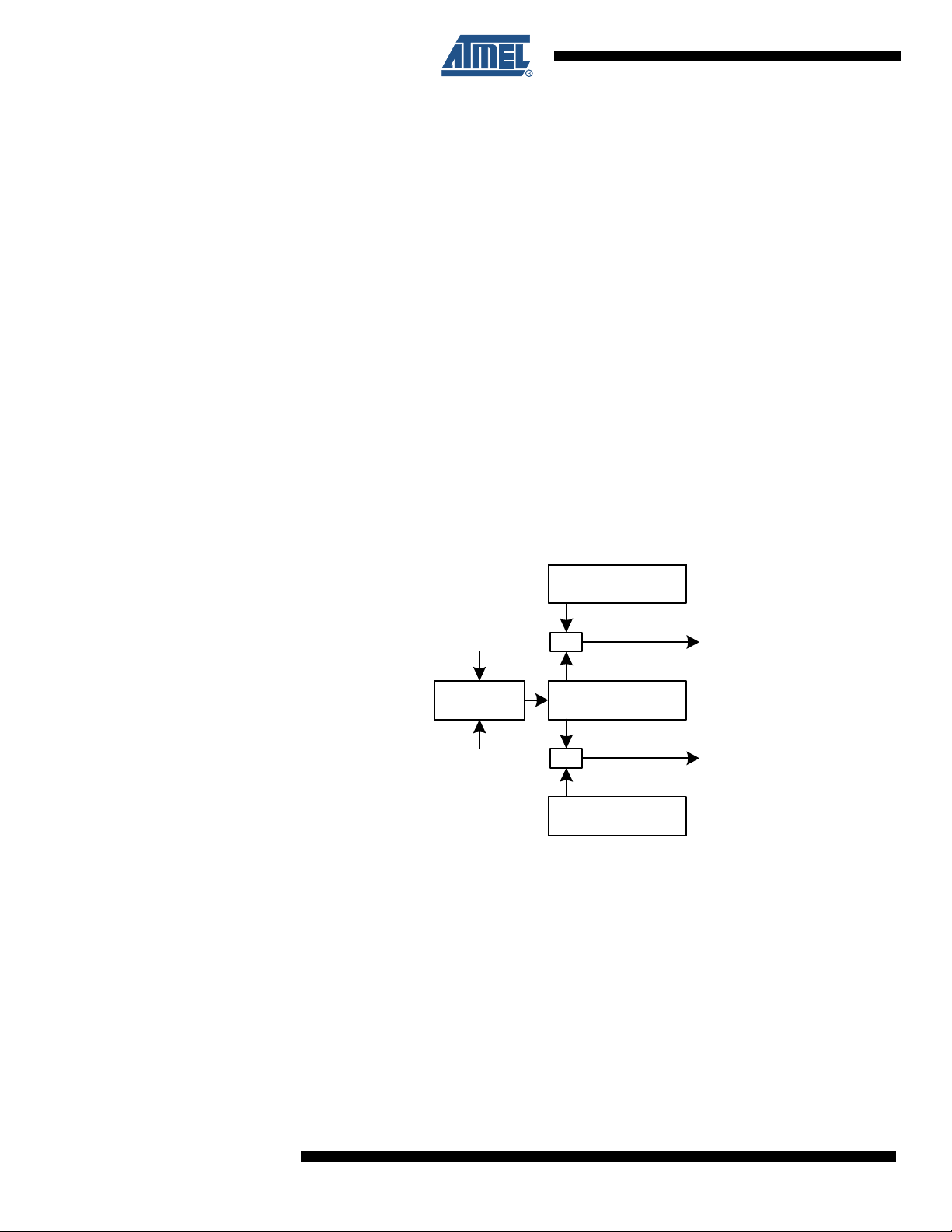
for details, see Figure 17-1 on page 28.
A wide range of Resolution and Time-out periods can be conf igure d usin g the RTC. With a maximum resolution of 30.5 µs, time-out periods range up to 2000 seconds. With a resolution of 1
second, maximum time-out period is over 18 hours (65536 se conds).
Figure 17-1. Real-time Counter overview
32 kHz
10-bit
prescaler
1 kHz
16-bit Top Value
Overflow
=
16-bit Timer
=
Compare Match
16-bit Compare
28
8069A–AVR–02/08

18. TWI - Two-Wire Interface
18.1 Features
• 3 Identical TWI peripherals
• Simple yet Powerfu l an d Flexible Communication Interface
• Both Master and Slave Operation Supported
• Device can Operate as Transmitter or Receiver
• 7-bit Address Space Allows up to 128 Different Slave Addresses
• Multi-master Arbitration Support
• Up to 400 kHz Data Transfer Speed
• Slew-rate Limited Output Drivers
• Noise Suppression Circuitry Rejects Spikes on Bus Lines
• Fully Programmable Slave Address with General Call Support
• Address Recognition Causes Wake-up when in Sleep Mode
2
• I
C and System Management Bus (SMBus) compliant
18.2 Overview
The Two-wire Interface (TWI) is a bi-directional bus with only two lines, the clock (SCL) and the
data (SDA). The protocol makes it possible to interconnect up to 128 individually addressable
devices. Since it is a multi-master bus, one or more devices capab le of taking cont rol of th e bus,
can be connected.
ATxmega A4
The only external hardware needed to implement the bus is a single pull-up resistor for each of
the TWI bus lines. Mechanisms for resolving bus contention are inherent in the TWI protocol.
PORTC, PORTD, and PORTE each have one TWI. Notation of these peripherals are TWIC,
TWID, and TWIE.
8069A–AVR–02/08
29

ATxmega A4
19. SPI - Serial Peripheral Interface
19.1 Features
• 2 Identical SPI peripherals
• Full-duplex, Three-wire Synchronous Data Transfer
• Master or Slave Operation
• LSB First or MSB First Data Transfer
• Seven Programmable Bit Rates
• End of Transmission Interrupt Flag
• Write Collision Flag Protection
• Wake-up from Idle Mode
• Double Speed (CK/2) Master SPI Mode
19.2 Overview
The Serial Peripheral Interface (SPI) allows high-speed synchronous data transfer between different devices. Devices can communicate using a master-slave scheme, and data a re
transferred both to and from the devices simultaneously.
PORTC and PORTD each have one SPI. Notation of these peripherals are SPIC and SPID.
30
8069A–AVR–02/08

20. USART
20.1 Features
20.2 Overview
ATxmega A4
• 5 Identical USART peripherals
• Full Duplex Operation (Independent Serial Receive and Transmit Registers)
• Asynchronous or Synchronous Operation
• Master or Slave Clocked Synchronous Operation
• High-resolution Arithmetic Baud Rate Generator
• Supports Serial Frames with 5, 6, 7, 8, or 9 Data Bits and 1 or 2 Stop Bits
• Odd or Even Parity Generation and Parity Check Supported by Hardware
• Data OverRun Detection
• Framing Error Detection
• Noise Filtering Includes False Start Bit Detection and Digital Low Pass Filter
• Three Separate Interrupts on TX Complete, TX Data Register Empty and RX Complete
• Multi-processor Communicat ion Mode
• Double Speed Asynchronous Communication Mode
• IrDA
The Universal Synchronous and Asynchronous serial Receiver and Transmitter (USART) provides highly flexible serial communication device. The frame format can be customized to
support a wide range of standards, and the USART implements different error detection.
PORTC and PORTD each have two USARTs. PORTE has one USART. Notation of these
peripherals are USARTC0, USARTC1, USARTD0, USARTD1, and USARTE0.
8069A–AVR–02/08
31

ATxmega A4
21. IRCOM - IR Communication Module
21.1 Features
• Pulse modulation/demodulation for infrared communication
• IrDA 1.4 Compatible for baud rates up to 115.2 kbps
• Selectable pulse modulation scheme
– 3/16 of baud rate period
– Fixed pulse period, 8-bit programmable
– Pulse modulation disabled
• Built in filtering
• Can be connected to and used by any USART and one USART at the time
21.2 Overview
XMEGA contains an Infrared Communication Module (IRCOM) IrDA 1.4 compatible module for
baud rates up to 115.2 kbps. This supports three modulat ion sch emes: 3/ 16 of baud rate pe rio d,
fixed programmable pulse time based on the Peripheral Clock speed , or pulse modulation disabled. There is one IRCOM available, and this can be connected to any USART to enable
infrared pulse coding/decoding for that USART.
32
8069A–AVR–02/08

22. Crypto Engine
22.1 Features
22.2 Overview
ATxmega A4
• Data Encryption Standard (DES) CPU instruction
• Advanced Encryption Standard (AES) crypto module
• DES Instruction
– Encryption and Decryption
– DES and triple-DES supported
– Single-cycle DE S instruction
– Encryption/Decryption in 16 clock cycles per 8-byte block
• AES Crypto Module
– Encryption and Decryption
– Support 128-bit keys
– Support XOR data load mode to the State memory
– Encryption/Decryption in 375 clock cycles per 16-byte block
The Advanced Encryption Standard (AES) and Data Encryption Standard (DES) are two commonly used standards for encryption. These are supported through an AES peripheral module
and a DES core instruction.
DES is supported by a DES instruction in the AVR XMEGA CPU. The 8-byte key and 8-byte
data blocks must be loaded into the Register file, and then DES must be executed 16 times to
encrypt/decrypt the data block.
The AES Crypto Module encrypts and decrypts 128-bit dat a blocks with the use of a 12 8-bit key.
The key and data must be loaded into the module before encryption/decryption is started. It
takes 375 peripheral clock cycles before encrypted/decrypted data can be read ou t.
8069A–AVR–02/08
33

ATxmega A4
23. ADC - 12-bit Analog to Digital Converter
23.1 Features
• Two ADCs with 12-bit resolution
• 2 Msps conversion rate for each ADC
• Signed- and Unsigned conversions
• 4 result registers with individual input channel control for each ADC
• 8 single ended inputs for each ADC
• 8x4 differential inputs for each ADC
• Gain of 1, 2, 4, 8, 16, 32 or 64
• Selectable accuracy of 8- or 12-bit.
• Built-in Gain Calibration
• Internal- or External Reference selection
• Event triggered conversion for accurate timing
• DMA transfer of conversion results
• Interrupt/Event on compare result
23.2 Overview
The XMEGA A4 devices has two Analog to Digital Converters (ADC), see Figure 23-1 on page
35. The two ADC modules can be operated simultaneously, individually or synchronized.
The ADC converts analog voltages to digital values.The ADC has 12-bit resolution and is capable of converting up to 2 million samples per second. The input selection is flexible, and both
single-ended and differential measurements can be done. The ADC provides both signed and
unsigned results, and an optional gain stage is available to increase the dynamic range of the
ADC.
The ADC uses Successive Approximation Result (SAR) ADC . A SAR ADC meas ures one bi t of
the conversion result a time. The ADC has a pipe line architectu re. This means that a new analog
voltage can be sampled and a new ADC measurement started while other ADC measurements
are ongoing.
ADC measurements can either be started by the application software or an incoming event from
another peripheral in the device. Four different result registers with individual channel selection
(MUX registers) are provided to make it easier for the application to keep track of the data. It is
also possible to use DMA to move ADC results directly to memory or peripherals.
Both internal and external analog reference voltages can be used. A very accurate internal 1.0V
reference is available, providing a conversion range from 0 - 1.0 V in unsigne d mode and -1.0 to
1.0V in signed mode.
34
8069A–AVR–02/08

Figure 23-1. ADC overview
Channel A MUX selection
Channel B MUX selection
Channel C MUX selection
Channel D MUX selection
ATxmega A4
Internal inputs
Pin inputsPin inputs
1-64 X
Configuration
Reference selection
ADC
Event
Trigger
Channel A
Register
Channel B
Register
Channel C
Register
Channel D
Register
Each ADC has 4 registers defining a MUX selection with a corresponding result register. This
means that 4 channels may be sampled within 1.5 µs without any intervention by the ap plication
other than starting the conversion, and the result will be available in 4 data registers.
The ADC may be configured to make 8-, 10- or 12-bit results, reducing the conversion time
(propagation delay) from 5.3 µs for 12-bit to 3.1 µs for 8-bit resolution.
ADC conversion results are provided left- or right adjusted with optional ‘1’ or ‘0’ padding. This
eases calculation when the result is represented as a signed integer (signed 16-bit number).
PORTA and PORTB each have one ADC. Notation of these peripherals are ADCA and ADCB.
8069A–AVR–02/08
35

ATxmega A4
24. DAC - 12-bit Digital to Analog Converter
24.1 Features
• One DAC with 12-bit resolution
• Up to 1 Msps conversion rate for each DAC
• Flexible conversion range
• Multiple trigger sources
• 1 continuous time or 2 Sample and Hold (S/H) outputs for each DA C
• Built-in offset and gain calibration
• High drive capabilities
• DAC Power reduction mode
24.2 Overview
The XMEGA A4 features one 12-bit, 1 Msps DAC with built-in calibration of offset and gain, see
Figure 24-1 on page 36.
A DAC converts a digital value into an analog signal. The DAC ma y use the bandg ap referenc e
voltage as upper limit for conversion, but it is also possible to use the supply voltage or any
applied voltage in-between. An external reference input is shared with the ADC reference input.
Figure 24-1. DAC overview
Reference selection
Configuration
Channel A
Register
DAC
Channel B
Register
Event
Trigger
Channel A
Channel B
The DAC has one continuous output with high drive capabilities for both resistive and capacitive
loads. It is also possible to split the continuous time channel into two Sample and Hold (S/H)
channels; each with separate data conversion registers.
A DAC conversion may be started from the application software by writing the data conversion
registers. The DAC may also be configured to do conversions triggered by the Event System to
have regular timing independent of the application. DMA may be used for transferring data from
memory location to DAC data registers.
The DAC has a built-in calibration system that removes offset and gain error.
The DAC belongs to PORTB. Notation of this peripheral is DACB.
36
8069A–AVR–02/08

25. AC - Analog Comparator
25.1 Features
• Two Analog Comparators
• Selectable Power vs. Speed
– 20 µA/500 ns active current consumption/propagation delay or
– 130 µA/30 ns active current consumption/propagation delay
• Selectable hysteresis
– 0, 20 mV, 50 mV
• Analog Comparator output available on pin
• Flexible Input Selection
• Basic interrupt and event generation on
– Rising edge
– Falling edge
–Toggle
• Window function interrupt and event generation on
– Signal above window
– Signal inside window
– Signal below window
25.2 Overview
ATxmega A4
The XMEGA A4 features four An alog Com parators (AC). An An alog Comp arator com pares tw o
voltages, and the output indicates which input is largest. T he Analog Comparat or may be co nfigured to give interrupt requests and/or events upon several different combinations of input
change.
Both hysteresis and propagation delays may be adjusted in order to find the optimal operation
for each application.
The Analog Comparators are always grouped in pairs (AC0 and AC1) on each analog port. They
have identical behavior but separate control regi sters
The AC belongs to PORTA. Notations are ACA0 and ACA1.
Figure 25-1. Analog comparator overview
Pin inputs
Internal inputs
Scaled inputs
Pin inputs
Internal inputs
Interrupt
sensitivity
control
+
-
Interrupts
Events or
pin output
8069A–AVR–02/08
Scaled inputs
37

ATxmega A4
25.3 Input Selection
The Analog comparators have a very flexible input selection and the two comparators grouped
in a pair may be used to realize a window function. One pair of analog comparators is shown in
Figure 25-1 on page 37.
•
Input selection from pin
• Internal signals available on both analog comparator inputs
• 6-bit scale down of VCC, available on both analog comparator inputs
25.4 Window Function
The window function is realized by connecting the inputs of th e two analog comp arat ors in a pair
as shown in Figure 25-2 on page 38.
Figure 25-2. Analog comparator window function
– Pin 0, 1, 2 selectable to positive input of analog comparator
– Pin 0, 1, 3 selectable to negative input of analog comparator
– Bandgap Reference voltage
– Output from 12-bit DAC
+
AC0
Upper limit of window
Input signal
Interrupt
sensitivity
control
Interrupts
Events
Lower limit of window
+
AC1
-
38
8069A–AVR–02/08

26. OCD - On-chip Debug
26.1 Features
• Complete Program Flow Control
– Symbolic Debugging Support in Hardware
– Go, Stop, Reset, Step into, Step over, Step out, Run-to-Cursor
• 1 dedicated program address breakpoint or symbolic breakpoi nt for AVR studio/emulator
• 4 Hardware Breakpoints
• Unlimited Number of User Program Breakpoints
• Uses CPU for Accessing I/O, Data, and Program
• Non-Intrusive Operation
– Uses no hardware or software resources
• High Speed Operation
– No limitation on frequency of TCK versus system clock frequency
26.2 Overview
The XMEGA A4 has an On-chip debug (OCD) system that - in combination with Atmel’s development tools - provides all the necessary functions to debug an application.
ATxmega A4
8069A–AVR–02/08
39

ATxmega A4
27. Program, Debug and Test Interfaces
27.1 Features
• PDI - Program and Debug Interface (Atmel proprietary 2-pin interface)
• Access to the OCD system
• Programming of Flash, EEPROM, Fuses and Lock Bits
27.2 Overview
The PDI is the physical interface to access the debug facilities. When used, the PDI make use of
2 pins.
27.3 PDI - Program and Debug Interface
The PDI is an Atmel proprietary protocol for communication between the microcontroller and
Atmel’s development tools.
40
8069A–AVR–02/08

28. Pinout
The pinout of XMEGA A4 is shown in ”Block Diagram/Pinout” on page 2. In addition to general
I/O functionality, each pin may have several function. This will depend on which peripheral is
enabled and connected to the actual pin. Only one of the alternate pin functions can be used at
the time.
28.1 Alternate Pin Functions Description
The tables below shows the notation for all pin functions available and describe its function.
28.1.1 Operation/Power Supply
VCC Digital supply voltage
AVCC Analog supply voltage
GND Ground
28.1.2 Analog functions
ACxn Analog Comparator input port x pin y
ADCn Analog to Digital Converter input port x pin y
ATxmega A4
DACn Digital to Analog Converter output port x pin y
AREFx Analog Reference input port x pin
28.1.3 Timer functions
OCnx Output Compare Channel x for Timer n
_OCnx Inverted Output Compare Channel x for Timer n
28.1.4 Communication functions
SCL Serial Clock for TWI
SDA Serial Data for TWI
XCK0 Tr ansfer Clock for USART n
RxD0 Receiver Data for USART n
TxD0 Transmitter Data for USART n
_SS Slave Select for SPI
MOSI Master Out Slave In for SPI
MISO Master In Slave Out f o r SPI
SCK Serial Clock for SPI
8069A–AVR–02/08
41

ATxmega A4
28.1.5 Oscillators
TOSCn Timer Oscillator pin x
XTALn In put/Output to inverting Oscillator
28.1.6 DEBUG/SYSTEM functions
TEST Test pin
PROG Programming pin
RESET Reset pin
PDI_CLK Program and Debug Interface Clock
PDI_DATA Program and Debug Interface Data
28.2 Alternate Pin Functions
The tables below shows the main and alternate pin functions for all pins on each port. It also
shows which peripheral which make use of or enable the alte rnate pin function.
Table 28-1. Port A - Alternate functions
PORT A PIN # INTERRUPT ADCA POS ADCA NEG
GND 38
AVCC 39
PA0 40 SYNC ADC0 ADC0 ADC0 AC0 AC0 AREFA
PA1 41 SYNC ADC1 ADC1 ADC1 AC1 AC1
PA2 42 SYNC/ASYNC ADC2 ADC2 ADC2 AC2 DAC0
PA3 43 SYNC ADC3 ADC3 ADC3 AC3 AC3 DAC1
PA4 44 SYNC ADC4 ADC4 ADC4 AC4
PA5 1 SYNC ADC5 ADC5 ADC5 AC5 AC5
PA6 2 SYNC ADC6 ADC6 ADC6 AC6
PA7 3 SYNC ADC7 ADC7 ADC7 AC7 AC0 OUT
ADAA
GAINPOS
ADCA
GAINNEG ACA POS ACA NEG ACA OUT DACA REFA
Table 28-2. Port B - Alternate functions
PORT B PIN # INTERRUPT ADCB POS ADCB NEG ADCB GAINPOS ADCB GAINNEG ACB POS ACB NEG ACB OUT DACB REFB JTAG
PB0 4 SYNC ADC0 ADC0 ADC0 AC0 AC0 AREFB
PB1 5 SYNC ADC1 ADC1 ADC1 AC1 AC1
PB2 6 SYNC/ASYNC ADC2 ADC2 ADC2 AC2 DAC0
PB3 7 SYNC ADC3 ADC3 ADC3 AC3 AC3 DAC1
42
8069A–AVR–02/08

ATxmega A4
Table 28-3. Port C - Alternate functions
PORT C PIN # INTERRUPT TCC0 AWEXC TCC1 USARTC0 USARTC1 SPIC TWIC CLOCKOUT EVENTOUT
GND 8
VCC 9
PC0 10 SYNC OC0A OC0A SDA
PC1 11 SYNC OC0B OC0A XCK0 SCL
PC2 12 SYNC/ASYNC OC0C OC0B RXD0
PC3 13 SYNC OC0D OC0B TXD0
PC4 14 SYNC OC0C OC1A SS
PC5 15 SYNC OC0C OC1B XCK1 MOSI
PC6 16 SYNC OC0D RXD1 MISO
PC7 17 SYNC OC0D TXD1 SCK CLKOUT EVOUT
Table 28-4. Port D - Alternate functions
PORT D PIN # INTERRUPT TCD0 TCD1 USARTD0 USARTD1 SPDI TWID CLOCKOUT EVENTOUT
GND 18
VCC 19
PD0 20 SYNC OC0A SDA
PD1 21 SYNC OC0B XCK0 SCL
PD2 22 SYNC/ASYNC OC0C RXD0
PD3 23 SYNC OC0D TXD0
PD4 24 SYNC OC1A SS
PD5 25 SYNC OC1B XCK1 MOSI
PD6 26 SYNC RXD1 MISO
PD7 27 SYNC TXD1 SCK CLKOUT EVOUT
Table 28-5. Port E - Alternate functions
PORT E PIN # INTERRUPT TCE0 AWEXEI TCE1 USARTE0 USARTE1 SPIE TWIE CLOCKOUT EVENTOUT
GND 30
VCC 31
PE0 28 SYNC OC0A OC0A
PE1 29 SYNC OC0B OC0A XCK0 SCL
PE2 32 SYNC/ASYNC OC0C OC0B
PE3 33 SYNC OC0D OC0B TXD0
RXD0
8069A–AVR–02/08
SDA
43

ATxmega A4
29. Electrical Characteristics - TBD
29.1 Absolute Maximum Ratings*
Operating Temperature.................................. -55°C to +125°C
*NOTICE: Stresses beyond those listed under “Absolute
Maximum Ratings” may cause permanent dam-
Storage Temperature.....................................-65°C to +150°C
age to the device. This is a stress rating only and
functional operation of the device at these or
Voltage on any Pin with respect to Ground..-0.5V to V
CC
+0.5V
other conditions beyond those indicated in the
operational sections of this specification is not
Maximum Operating Voltage ............................................ 3.6V
implied. Exposure to absolute maximum rating
conditions for extended periods may affect
DC Current per I/O Pin...............................................20.0 mA
DC Current
V
and GND Pins................................ 200.0 mA
CC
device reliability.
29.2 DC Characteristics
TA = -40°C to 85°C, VCC = 1.8V to 3.6V (unless otherwise noted)
Symbol Parameter Condition Min. Typ. Max. Units
V
IL
V
IL1
V
IH
V
IH1
V
OL
V
OH
I
IL
I
IH
R
RST
R
PU
Input Low Voltage, except XTAL1 pin V
Input Low Voltage, XTAL1 pins V
Input High Voltage, except XTAL1 pin V
Input High Voltage, XTAL1 pin V
Output Low Voltage
Output High Voltage
Input Leakage
Current I/O Pin
Input Leakage
Current I/O Pin
Reset Pull-up Resistor kΩ
I/O Pin Pull-up Resistor kΩ
Active 32 MHz mA
Active 20 MHz mA
Power Supply Current
Active 8MHz mA
µA
µA
I
CC
Power-down mode
Note: 1. “Max” means the highest value where the pin is guaranteed to be read as low
2. “Min” means the lowest value where the pin is guaranteed to be read as high
44
Idle 32 MHz mA
Idle 20 MHz mA
WDT disabled µA
WDT slow sampling µA
WDT fast sampling
8069A–AVR–02/08

ATxmega A4
29.3 ADC Characteristics – TBD
Table 29-1. ADC Characteristics
Symbol Parameter Condition Min Typ Max Units
Resolution LSB
Integral Non-Linearity (INL) LSB
Differential Non-Linearity (DNL) LSB
Gain Error LSB
Offset Error LSB
Conversion Time µs
ADC Clock Frequency MHz
DC Supply Voltage mA
Source Impedance Ω
Start-up time µs
AVCC Analog Supply Current VCC - 0.3 VCC + 0.3 V
Table 29-2. ADC Gain Stage Characteristics
Symbol Parameter Condition Min Typ Max Units
Gain
Input Capacitance pF
Offset Error mV
Gain Error %
Signal Range V
DC Supply Current mA
Start-up time # clk cycles
8069A–AVR–02/08
45

ATxmega A4
29.4 DAC Characteristics – TBD
Table 29-3. DAC Characteristics
Symbol Parameter Condition Min Typ Max Units
Resolution LSB
Integral Non-Linearity (INL) LSB
Differential Non-Linearity (DNL) LSB
Gain Error LSB
Offset Error LSB
Calibrated Gain/Offset Error LSB
Output Range V
Output Settling Time µs
Output Capacitance nF
Output Resistance kΩ
Reference Input Voltage V
Reference Input Capacitance pF
Reference Input Resistance kΩ
Current Consumption mA
Start-up time µs
29.5 Analog Comparator Characteristics – TBD
Table 29-4. Analog Comparator Characteristics
Symbol Parameter Condition Min Typ Max Units
Offset mV
No
Hysteresis
High
High Speed mode
Propagation Delay
Low power mode
High Speed mode
Current Consumption
Low power mode
Start-up time µs
mVLow
ns
µA
46
8069A–AVR–02/08

30. Typical Characteristics - TBD
ATxmega A4
8069A–AVR–02/08
47

ATxmega A4
31. Peripheral Module Address Map
The address maps shows the base address for each peripheral and module in XMEGA A4. For
complete register description and summa ry for each peripheral modu le, refer to the XMEGA A
Manual.
Base Address Name Description
0x0000 GPIO General Purpose IO Registers
0x0010 VPORT0 Virtual Port 0
0x0014 VPORT1 Virtual Port 1
0x0018 VPORT2 Virtual Port 2
0x001C VPORT3 Virtual Port 2
0x0030 CPU CPU
0x0040 CLK Clock Control
0x0048 SLEEP Sleep Controller
0x0050 OSC Oscillator Control
0x0060 DFLLRC32M DFLL for the 32 MHz Internal RC Oscillator
0x0068 DFLLRC2M DFLL for the 2 MHz RC Oscillator
0x0070 PR Power Reduction
0x0078 RST Reset Controller
0x0080 WDT Watch-Dog Timer
0x0090 MCU MCU Control
0x00A0 PMIC Programmable MUltilevel Interrupt Controller
0x00B0 PORTCFG Port Configuration
0x00C0 AES AES Module
0x0100 DMA DMA Controller
0x0180 EVSYS Event System
0x01C0 NVM Non Volatile Memory (NVM) Controller
0x0200 ADCA Analog to Digital Converter on port A
0x0240 ADCB Analog to Digital Converter on port B
0x0320 DACB Digital to Analog Converter on port B
0x0380 ACA Analog Comparator pair on port A
0x0400 RTC Real Time Counter
0x0480 TWIC Two Wire Interface on port C
0x0490 TWID Two Wire Interface on port D
0x04A0 TWIE Two Wire Interfaceon port E
0x0600 PORTA Port A
0x0620 PORTB Port B
0x0640 PORTC Port C
0x0660 PORTD Port D
0x0680 PORTE Port E
0x07E0 PORTR Port R
0x0800 TCC0 Timer/Counter 0 on port C
0x0840 TCC1 Timer/Counter 1 on port C
0x0880 AWEXC Advanced Waveform Extension on port C
0x0890 HIRESC High Resolution Extension on port C
0x08A0 USARTC0 USART 0 on port C
0x08B0 USARTC1 USART 1 on port C
0x08C0 SPIC Serial Peripheral Interface on port C
0x08F8 IRCOM Infrared Communication Module
0x0900 TCD0 Timer/Counter 0 on port D
0x0940 TCD1 Timer/Counter 1 on port D
0x0990 HIRESD High Resolution Extension on port D
0x09A0 USARTD0 USART 0 on port D
0x09B0 USARTD1 USART 1 on port D
0x09C0 SPID Serial Peripheral Interface on port D
0x0A00 TCE0 Timer/Counter 0 on port E
0x0A80 AWEXE Advanced Waveform Extensionon port E
0x0A90 HIRESE High Resolution Extension on port E
0x0AA0 USARTE0 USART 0 on port E
48
8069A–AVR–02/08

32. Packaging information
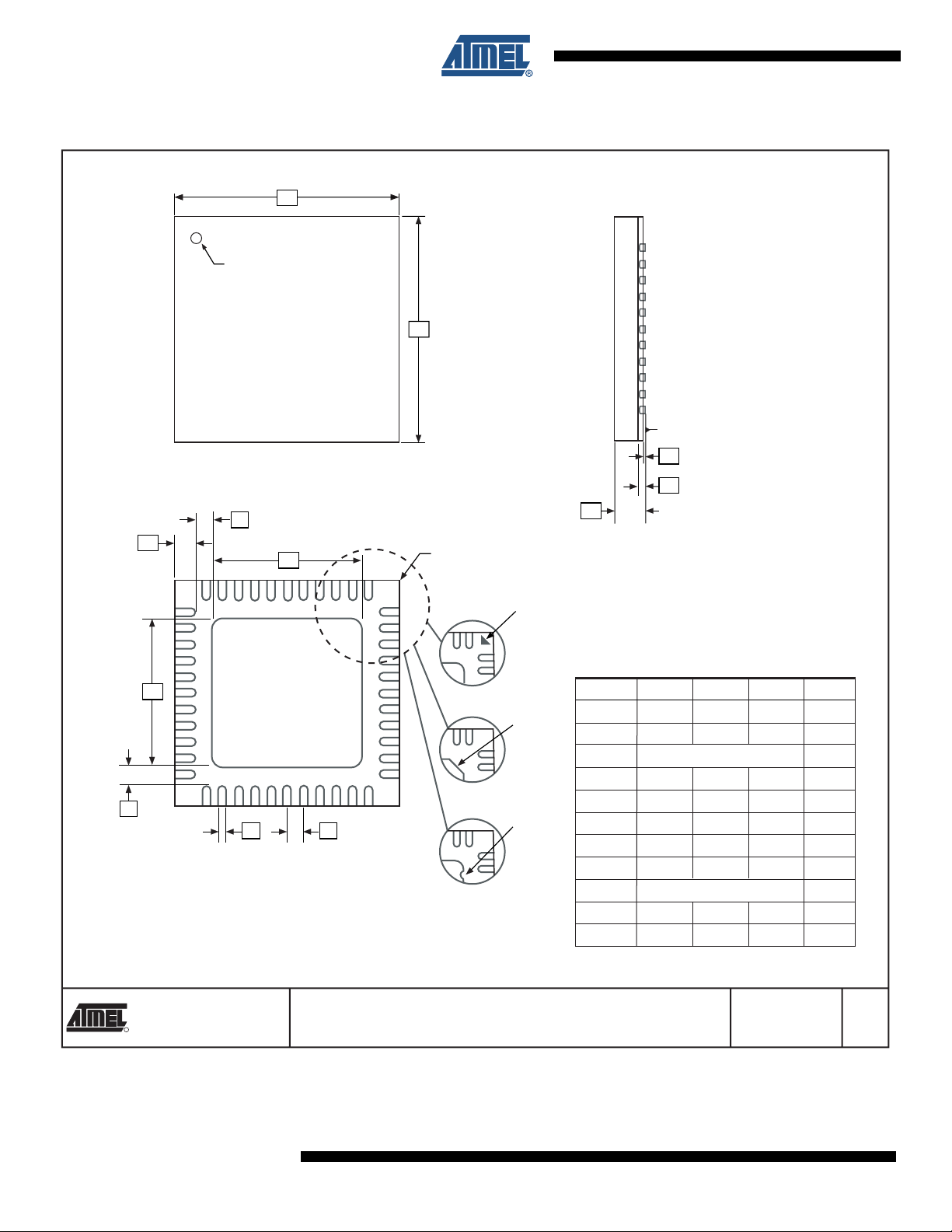
32.1 44A
PIN 1
PIN 1 IDENTIFIER
ATxmega A4
B
e
E1 E
D1
D
C
0˚~7˚
A1
L
Notes: 1. This package conforms to JEDEC reference MS-026, Variation ACB.
2. Dimensions D1 and E1 do not include mold protrusion. Allowable
protrusion is 0.25 mm per side. Dimensions D1 and E1 are maximum
plastic body size dimensions including mold mismatch.
3. Lead coplanarity is 0.10 mm maximum.
A2 A
SYMBOL
COMMON DIMENSIONS
(Unit of Measure = mm)
MIN
A – – 1.20
A1 0.05 – 0.15
A2 0.95 1.00 1.05
D 11.75 12.00 12.25
D1 9.90 10.00 10.10 Note 2
E 11.75 12.00 12.25
E1 9.90 10.00 10.10 Note 2
B 0.30 – 0.45
C 0.09 – 0.20
L 0.45 – 0.75
e 0.80 TYP
NOM
MAX
NOTE
2325 Orchard Parkway
R
San Jose, CA 95131
8069A–AVR–02/08
TITLE
44A, 44-lead, 10 x 10 mm Body Size, 1.0 mm Body Thickness,
0.8 mm Lead Pitch, Thin Profile Plastic Quad Flat Package (TQFP)
10/5/2001
DRAWING NO.
44A
REV.
B
49
ATxmega A4
32.2 44M1
D
Marked Pin# 1 ID
E
SEATING PLANE
TOP VIEW
K
L
D2
Pin #1 Corner
1
2
3
Option A
E2
Option B
K
b
e
Option C
BOTTOM VIEW
Note: JEDEC Standard MO-220, Fig. 1 (SAW Singulation) VKKD-3.
Pin #1
Triangle
Pin #1
Chamfer
(C 0.30)
Pin #1
Notch
(0.20 R)
A1
A3
A
SIDE VIEW
COMMON DIMENSIONS
(Unit of Measure = mm)
SYMBOL
A 0.80 0.90 1.00
A1 – 0.02 0.05
A3 0.25 REF
b 0.18 0.23 0.30
D
D2 5.00 5.20 5.40
E
E2 5.00 5.20 5.40
e 0.50 BSC
L 0.59 0.64 0.69
K 0.20 0.26 0.41
MIN
6.90 7.00 7.10
6.90 7.00 7.10
NOM
MAX
NOTE
2325 Orchard Parkway
R
San Jose, CA 95131
50
TITLE
44M1, 44-pad, 7 x 7 x 1.0 mm Body, Lead Pitch 0.50 mm,
5.20 mm Exposed Pad, Micro Lead Frame Package (MLF)
DRAWING NO.
44M1
8069A–AVR–02/08
5/27/06
REV.
G

33. Errata
33.1 All rev.
ATxmega A4
No known errata.
8069A–AVR–02/08
51

ATxmega A4
34. Datasheet Revision History
34.1 8069A – 02/08
1. Initi al revision.
52
8069A–AVR–02/08

Table of Contents
Features.....................................................................................................1
Typical Applications ................................................................................1
1 Block Diagram/Pinout ..............................................................................2
2 Ordering Information ...............................................................................3
3 Disclaimer .................................................................................................4
4 Overview ...................................................................................................4
5 Resources .................................................................................................4
5.1Recommended reading .............................................................................................4
6 AVR CPU ...................................................................................................5
6.1Features ....................................................................................................................5
6.2Overview ................. .......... ...... .......... .......... ......... .......... .......... .......... ...... .......... ........5
ATxmega A4
6.3Register File ..............................................................................................................6
6.4ALU - Arithmetic Logic Unit .... .... ... .................................................... ... ... ... ... ............6
6.5Program Flow ............................................................................................................6
7 Memories ..................................................................................................7
7.1Features ....................................................................................................................7
7.2Overview ................. .......... ...... .......... .......... ......... .......... .......... .......... ...... .......... ........7
7.3In-system Programmable Flash Program Memory ....................................................7
7.4SRAM Data Memory ..................................................................................................8
7.5EEPROM Data Memory ... ... ... .... ................................................... .... ... ... ... ...............8
7.6I/O Memory ................................................................................................................9
8 DMA - Direct Memory Access Controller .............................................10
8.1Features ..................................................................................................................10
8.2Overview .................... ............. .......... ............. ............. ............. ............. ............. ......10
9 Event System .......................................................................................... 11
9.1Features ..................................................................................................................11
9.2Overview ................. .......... ...... .......... .......... ......... .......... .......... .......... ...... .......... ......11
10 System Clock and Clock options .........................................................13
10.1Features ................................................................................................................13
10.2Overview ...................... ................ ................ ................ ................ ............. .............13
10.3Clock Options ........................................................................................................15
8069A–AVR–02/08
i

ATxmega A4
11 Power Management and Sleep Modes .................................................16
11.1Features ................................................................................................................16
11.2Overview ...................... ................ ................ ................ ................ ............. .............16
11.3Sleep Modes ..........................................................................................................16
12 System Control and Reset ....................................................................18
12.1Resetting the AVR .................................................................................................18
12.2Reset Sources .......................................................................................................18
12.3WDT - Watchdog Timer .................. ... .... ... ... .................................................... ... ...19
13 PMIC - Programmable Multi-level Interrupt Controller ....................... 20
13.1Features ................................................................................................................20
13.2Overview ...................... ................ ................ ................ ................ ............. .............20
13.3Interrupt vectors . ... ... .... ................................................... .... ...................................20
14 I/O Ports .................................................................................................. 22
14.1Features ................................................................................................................22
14.2Overview ...................... ................ ................ ................ ................ ............. .............22
14.3I/O configuration ................................ .... ... ... ... ... ....................................................22
14.4Input sensing .........................................................................................................25
14.5Port Interrupt ..........................................................................................................25
15 T/C - 16-bits Timer/Counter with PWM .................................................26
15.1Features ................................................................................................................26
15.2Overview ...................... ................ ................ ................ ................ ............. .............26
16 AWEX - Advanced Waveform Extension .............................................27
16.1Overview ...................... ................ ................ ................ ................ ............. .............27
17 RTC - Real-Time Counter .......................................................................28
17.1Features ................................................................................................................28
17.2Overview ...................... ................ ................ ................ ................ ............. .............28
18 TWI - Two-Wire Interface .......................................................................29
18.1Features ................................................................................................................29
18.2Overview ...................... ................ ................ ................ ................ ............. .............29
19 SPI - Serial Peripheral Interface ............................................................30
19.1Features ................................................................................................................30
19.2Overview ...................... ................ ................ ................ ................ ............. .............30
20 USART ..................................................................................................... 31
ii
8069A–AVR–02/08

20.1Features ................................................................................................................31
20.2Overview ...................... ................ ................ ................ ................ ............. .............31
21 IRCOM - IR Communication Module .....................................................32
21.1Features ................................................................................................................32
21.2Overview ...................... ................ ................ ................ ................ ............. .............32
22 Crypto Engine .........................................................................................33
22.1Features ................................................................................................................33
22.2Overview ...................... ................ ................ ................ ................ ............. .............33
23 ADC - 12-bit Analog to Digital Converter ............................................. 34
23.1Features ................................................................................................................34
23.2Overview ...................... ................ ................ ................ ................ ............. .............34
24 DAC - 12-bit Digital to Analog Converter ............................................. 36
24.1Features ................................................................................................................36
ATxmega A4
24.2Overview ...................... ................ ................ ................ ................ ............. .............36
25 AC - Analog Comparator .......................................................................37
25.1Features ................................................................................................................37
25.2Overview ...................... ................ ................ ................ ................ ............. .............37
25.3Input Selection .......................................................................................................38
25.4Window Function ...................................................................... ... ..........................38
26 OCD - On-chip Debug ............................................................................39
26.1Features ................................................................................................................39
26.2Overview ...................... ................ ................ ................ ................ ............. .............39
27 Program, Debug and Test Interfaces ...................................................40
27.1Features ................................................................................................................40
27.2Overview ...................... ................ ................ ................ ................ ............. .............40
27.3PDI - Program and Debug Interface ......................................................................40
28 Pinout ...................................................................................................... 41
28.1Alternate Pin Functions Description ......................................................................41
28.2Alternate Pin Functions .........................................................................................42
29 Electrical Characteristics - TBD ............................................................44
29.1Absolute Maximum Ratings* ................................................. ... ... .... ... ... ................44
29.2DC Characteristics .................................................................................................44
29.3ADC Characteristics – TBD ...................................................................................45
8069A–AVR–02/08
iii

ATxmega A4
29.4DAC Characteristics – TBD ...................................................................................46
29.5Analog Comparator Characteristics – TBD ...........................................................46
30 Typical Characteristics - TBD ...............................................................47
31 Peripheral Module Address Map .......................................................... 48
32 Packaging information ..........................................................................49
32.144A ........................................................................................................................49
32.244M1 ........................ ............. .......... ............. ............. ............. ............. ............. ......50
33 Errata ....................................................................................................... 51
33.1All rev. ....................................................................................................................51
34 Datasheet Revision History ...................................................................52
34.18069A – 02/08 .......................................................................................................52
Table of Contents.......................................................................................i
iv
8069A–AVR–02/08

ATxmega A4
8069A–AVR–02/08
v

Headquarters International
Atmel Corporation
2325 Orchard Parkway
San Jose, CA 95131
USA
Tel: 1(408) 441-0311
Fax: 1(408) 487-2600
Atmel Asia
Room 1219
Chinachem Golden Plaza
77 Mody Road Tsimshatsui
East Kowloon
Hong Kong
Tel: (852) 2721-9778
Fax: (852) 2722-1369
Product Contact
Web Site
www.atmel.com
Literature Requests
www.atmel.com/literature
Atmel Europe
Le Krebs
8, Rue Jean-Pierre Timbaud
BP 309
78054 Saint-Quentin-enYvelines Cedex
France
Tel: (33) 1-30-60-70-00
Fax: (33) 1-30-60-71-11
Technical Support
avr@atmel.com
Atmel Japan
9F, Tonetsu Shinkawa Bldg.
1-24-8 Shinkawa
Chuo-ku, Tokyo 104-0033
Japan
Tel: (81) 3-3523-3551
Fax: (81) 3-3523-7581
Sales Contact
www.atmel.com/contacts
Disclaimer: The information in this document is provided in connection with Atmel products. No license, express or implied, by estoppel or otherwise, to any
intellectual property right is granted by this document or i n connection with the sale of Atmel products. EXCEPT AS SET FORTH IN ATMEL’S TERMS AND CONDI-
TIONS OF SALE LOCATED ON ATMEL’S WEB SITE, ATMEL ASSUMES NO LIABILITY WHATSOEVER AND DISCLAIMS ANY EXPRESS, IMPLIED OR STATUTORY
WARRANTY RELATING TO ITS PRODUCTS INCLUDING, BUT NOT LIMITED TO, THE IMPLIED WARRANTY OF MERCHANTABILITY, FITNESS FOR A PARTICULAR
PURPOSE, OR NON-INFRINGEMENT. IN NO EVENT SHALL ATMEL BE LIABLE FOR ANY DIRECT, INDIRECT, CONSEQUENTIAL, PUNITIVE, SPECIAL OR INCIDENT AL DAMAGES (INCLUDING, WITHOUT LIMITATION, DAMAGES FOR LOSS OF PROFITS, BUSINESS INTERRUPTI ON, OR L OSS OF INFORMATION) ARISING OUT OF
THE USE OR INABILITY TO USE THIS DOCUMENT, EVEN IF ATMEL HAS BEEN ADVISED OF THE POSSIBILITY OF SUCH DAMAGES. Atmel makes no
representations or warranties with respect to the accuracy or completeness of the contents of this document and reserves the right to make changes to specifications
and product descriptions at any time without notice. Atmel does not make any commitment to update the information contained here in. Unless specifically provided
otherwise, Atmel products are not suitable for, and shall not be used in, automotive applications. Atmel’s products are not intended, authorized, or warranted for use
as components in applications intended to suppor t or sustain life.
© 2008 Atmel Corporation. All rights reserved. Atmel®, logo and combinations thereof, AVR® and others are registered trademarks or trade-
marks of Atmel Corporation or its subsidiaries. Other term s and product names may be trademarks of others.
8069A–AVR–02/08
 Loading...