

Page 1

Atmel ATF15xx Family: ISP Devices
............................................................................................................
User Guide
BDTIC www.bdtic.com/Semiconductor
Page 2

Table of Contents
Section 1
Introduction ........................................................................................... 1-1
1.1 Benefits .....................................................................................................1-2
1.2 Atmel JTAG ISP Interface .........................................................................1-2
1.2.1 Single-device Programming ...............................................................1-2
1.2.2 Multiple-device Programming .............................................................1-3
1.3 Design Considerations..............................................................................1-4
1.3.1 JTAG Interface with Atmel-Synario ....................................................1-4
1.3.2 JTAG Interface with Atmel-WinCUPL.................................................1-5
Section 2
Atmel-ISP Package Options ................................................................. 2-1
2.1 System Requirements...............................................................................2-2
Section 3
Atmel-ISP Software ..............................................................................3-1
3.1 ATMISP Commands .................................................................................3-3
3.1.1 Device Properties Dialog Box.............................................................3-3
3.1.2 Description of ATMISP File Menu Commands ...................................3-4
3.1.3 Description of ATMISP Edit Menu Commands...................................3-6
3.1.4 Description of ATMISP View Menu Commands .................................3-8
3.1.5 Description of ATMISP Process Menu Commands ............................3-8
3.1.6 Description of ATMISP Help Menu Commands ...............................3-10
3.2 ATMISP Hidden Commands (Advanced Users Only).............................3-10
Section 4
Atmel-ISP Hardware .............................................................................4-1
4.1 Atmel-ISP Board Description ....................................................................4-1
4.1.1 Optional Features on Atmel-ISP Board Useful for Prototyping...........4-2
4.2 Atmel-ISP Daughter Board .......................................................................4-4
4.3 Atmel-ISP Cable .......................................................................................4-5
Atmel ATF15xx Family: ISP Devices User Guide i
Rev. 1936A-07/01
Page 3

Table of Contents
Section 5
Getting Started...................................................................................... 5-1
5.1 In-System Programming Procedure..........................................................5-1
5.1.1 Setting Up the Atmel-ISP Board .........................................................5-1
5.1.2 Setting Up Your Target System..........................................................5-2
5.1.3 Running the Atmel-ISP Software........................................................5-2
5.1.3.1 Setting Up the Chain File .............................................................5-2
5.1.3.2 Executing ISP on Atmel ISP Devices...........................................5-3
5.2 Using ByteBlaster/ByteBlasterMV Cable with Atmel ISP Devices ............5-4
5.3 Creating SVF Files ....................................................................................5-4
5.4 Creating Jam Files ....................................................................................5-5
5.5 Creating PCF Files....................................................................................5-5
Section 6
JTAG ISP Guidelines............................................................................6-1
Section 7
Troubleshooting .................................................................................... 7-1
7.1 ATMISP Messages ...................................................................................7-1
7.1.1 Error Messages ..................................................................................7-1
7.1.2 Warning Messages .............................................................................7-6
7.2 Notices ......................................................................................................7-8
Section 8
Ordering Information.............................................................................8-1
ii Atmel ATF15xx Family: ISP Devices User Guide
Page 4

Section 1
Introduction
Traditionally, programmable logic devices have been programmed on external device
programmers that provide the necessary programming signals and algorithms to program the devices. With the advent of In-System Programming (ISP), ISP devices can
now be programmed on your own circuit board. This manual describes the design methods and requirements for implementing in-system Programming on Atmel ISP Complex
Programmable Logic Devices (CPLDs). All devices in the ATF15xx family are ISP capable CPLDs (except ATF1500/A/AL/ABV), and ISP is implemented on these devices
through the Joint Test Action Group (JTAG) interface. The following devices are supported by the Atmel-ISP software.
• ATF1502AS/ASL/ASV/ASVL
• ATF1504AS/ASL/ASV/ASVL
• ATF1508AS/ASL/ASV/ASVL
The three essential components for in-system programming are the Atmel-ISP software,
ISP hardware board and ISP download cable. These components and their usage will
be discussed in detail in this user guide.
In addition to these three components, a JEDEC file is also necessary to program any
Atmel ISP devices. This JEDEC file can be created by compiling a design file using a
compiler software that supports the Atmel ISP devices. Atmel also provides translator
software (POF2JED.EXE) to convert output files from the competitor’s programming format to a JEDEC file compatible with the Atmel ISP family of devices. This conversion
utility is available on Atmel’s web site and BBS. For further information on POF2JED,
please refer to the application note, “ATF15xx Product Family Conversion”, available on
Atmel’s web site, BBS and Fax-on-Demand. After you have created the JEDEC files for
all Atmel ISP devices, you are ready to program them on your circuit/Atmel-ISP board.
Using the Atmel-ISP software, download cable and ISP hardware board, you can program, verify, blank check, erase, secure and read from any Atmel ISP device directly
from your personal computer while the devices are still on the circuit boards.
URL: www.atmel.com
BBS: 1-408-436-4309
Fax-on-Demand: 1-800-29-ATMEL/1-800-292-8635 (North America)
1-408-441-0732 (International)
Atmel ATF15xx Family: ISP Devices User Guide 1-1
Rev. 1936A-07/01
Page 5

Introduction
1.1 Benefits In-system programming allows you to program and reprogram devices after they are
soldered onto your circuit board. ISP eliminates the extra handling step required in the
manufacturing process to program the devices on an external programmer before placing them on your circuit board. Eliminating this step reduces the possibility of damaging
the delicate leads of high pin count surface mount devices or damaging the device
through electrostatic discharge (ESD). ISP also allows you to make design changes and
field upgrades without removing the Atmel ISP devices from the circuit board. In addition, ISP allows you to use your Automatic Test Equipment (ATE) to perform ISP
operations on your ISP devices and integrate these ISP operations with the normal production test flow.
1.2 Atmel JTAG ISP Interface
1.2.1 Single-device Programming
The Atmel JTAG ISP interface is a 4-pin, 3- or 5-volt interface compatible with the Joint
Test Action Group (JTAG) IEEE 1149.1a-1993 Standard. All Atmel ISP devices can be
programmed, verified and erased through this interface. The JTAG interface is a serial
interface consisting of the TCK, TMS, TDI and TDO signals, and a JTAG Test Access
Port (TAP) Controller. The TCK pin is the serial data clock. Programming data is clocked
by this pin. The TDI pin is the serial data input. It is used to shift programming data into
the Atmel device. The TDO pin is the serial data output. It is used to shift out data from
the Atmel device. The TMS pin is a mode select pin. It controls the state of the JTAG
TAP controller.
Atmel ISP devices are fully JTAG-compatible and support the required Boundary Scan
Test (BST) operations specified in the JTAG standard. Atmel ISP devices can be configured to be a part of a JTAG BST chain with other JTAG devices for in-circuit testing of
your system board. With this feature, you can test Atmel CPLDs along with other
devices without resorting to bed-of-nails testing.
For more information about Atmel ISP, BST or the POF-to-JEDEC translator, please
contact Atmel PLD Applications at:
Hotline: 1-408-436-4333
E-mail: pld@atmel.com
URL: www.atmel.com
The Atmel JTAG ISP interface can be configured to program a single Atmel ISP device.
The JTAG configuration for a single device is shown in Figure 1-1. When the Atmel ISP
device is configured in this way, a register appears between the TDI and TDO pins of
the device. The size of the register depends on the JTAG instruction width and the data
being shifted in for that instruction. The JTAG interface pins for the Atmel ISP device
must be connected to a 10-pin header on your circuit board. This header mates with the
ISP download cable and allows the Atmel-ISP software to transfer programming data
from your personal computer to the Atmel ISP device. The pinout for the JTAG pins for
different Atmel ISP devices is listed in Table 1-1.
1-2 Atmel ATF15xx Family: ISP Devices User Guide
Page 6
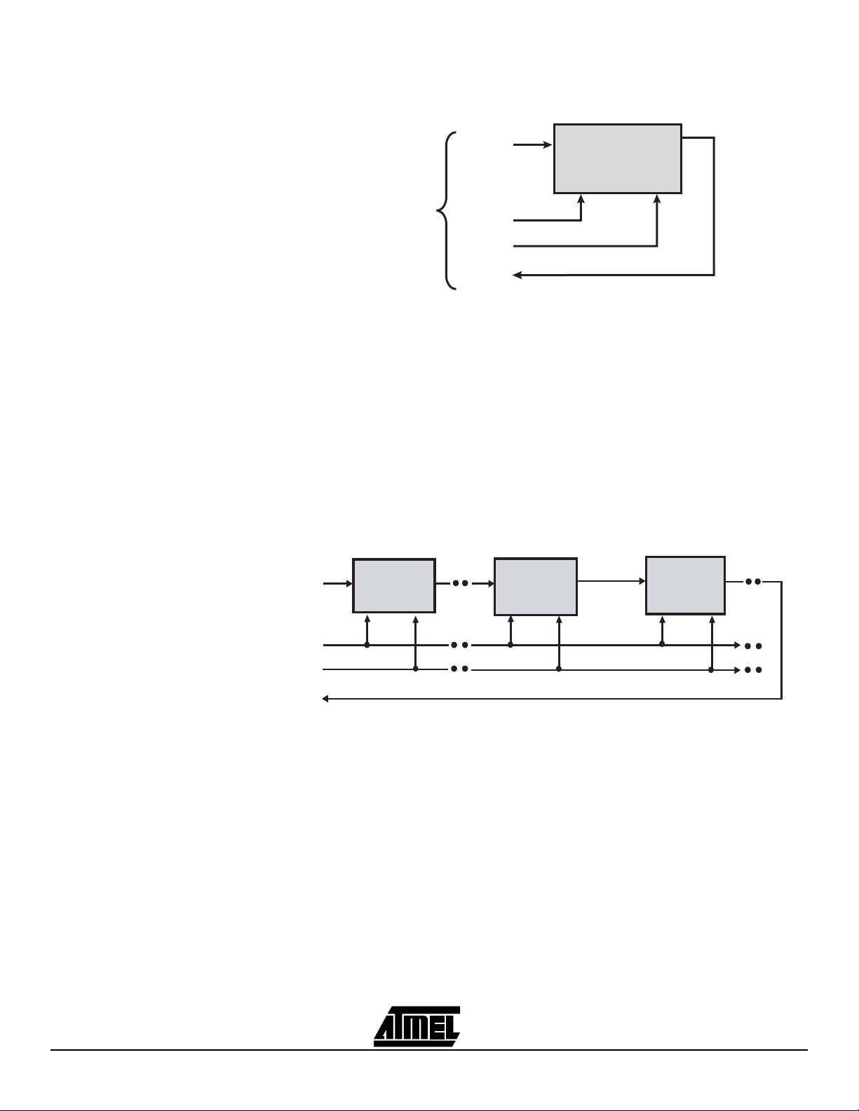
Figure 1-1. Single-device JTAG Configuration
Introduction
Atmel ISP Device
1.2.2 Multiple-device Programming
TDI
TDI
TMS
TDO
TCK
JTAG
INTERFACE
TMS
TCK
TDO
Note: You will need to reserve space on your circuit board to accommodate a 10-pin
male header for the JTAG interface. The pinout for this header must match the
Atmel-ISP cable connector pinout. The JTAG interface pins for each Atmel
device must also be connected to this header.
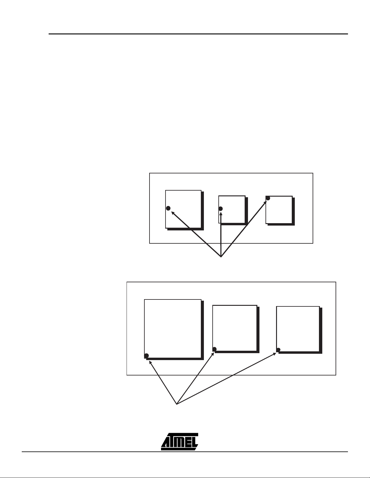
Atmel ISP devices can be configured as part of a JTAG daisy chain. Once the daisy
chain is configured, multiple Atmel ISP devices can be programmed at the same time
(Parallel ISP). Figure 1-2 shows the configuration for multiple-device programming.
Figure 1-2. Multiple-device JTAG Chain Configuration
Non-Atmel
Device
Atmel ISP Device
Atmel ISP Device
TDI
TMS
TCK
TDO
TDI TDO
TMS TCK
TDI
TMS
TDO
TCK
TDI TDO
TMS
TCK
TDI, TMS, TCK and TDO comprise the JTAG interface. The ISP software allows you to
create a JTAG daisy chain for multiple devices, including non-Atmel devices, and implement parallel ISP for Atmel devices.
To create a JTAG daisy chain to implement parallel ISP, perform the following steps:
1. Connect the TMS and TCK pin for each device in the JTAG chain to the appropriate pins on the 10-pin header on your circuit board.
2. Connect the TDI pin from the first device to the TDI pin on the 10-pin header.
3. Connect the TDO pin from first device to the TDI pin of the next device. Continue
this process until all except the last one are connected.
4. Connect the TDO pin from the last device to the TDO pin on the 10-pin header.
Atmel ATF15xx Family: ISP Devices User Guide 1-3
Page 7

Introduction
A device residing in any location in the JTAG chain can be programmed exclusive of all
others. You can use the Atmel-ISP software to place all other devices except the one to
be programmed in the JTAG Bypass mode. When the other devices are placed in this
mode, a 1-bit flow-through register appears between the TDI and TDO pins for these
devices. During a programming operation, JTAG programming data passes through
devices in the JTAG Bypass mode but is loaded into the device that is to be programmed. This allows only the device you want to program to be loaded with JEDEC
fuse data.
1.3 Design Considerations
Performing ISP on Atmel ISP devices requires that you reserve design resources for the
JTAG interface. You will need to reserve four I/O pins for the TMS, TDI, TDO and TCK
pins. The pin numbers for these pins depend on which Atmel ISP device you are using
and its package type. Refer to Table 1-1 for pinout information. The JTAG standard also
requires that the TMS and TDI pins be pulled up for each device in the JTAG chain. The
Atmel ISP devices have an internal pull-up feature for these pins which, when enabled,
saves the need for external pull-up resistors. Once you have reserved logic resources
for the JTAG interface, you can program, verify and erase any Atmel ISP device using
the Atmel-ISP software.
Note: Even though you must reserve certain I/O pins in your design for the JTAG
interface, you can still implement buried logic functions in the macrocells associated with these pins.
Table 1-1. Atmel ISP Device JTAG Pinout
JTAG
Pin
TDI1 712146 4 9
TDO323857717573112
TMS 7 13 19 23 17 15 22
44-pin
TQFP
44-pin
PLCC
68-pin
PLCC
84-pin
PLCC
100-pin
PQFP
100-pin
TQFP
160-pin
PQFP
TCK26325062646299
To use ISP to program Atmel devices, you must enable the JTAG interface. An optional
but recommended practice is to also enable the TMS and TDI internal pull-ups. Enabling
the JTAG interface requires choosing specific Atmel device types before compiling your
™
design. This procedure is outlined below for Atmel-Synario
and Atmel-WinCUPL™. If
you need to enable Atmel fitter properties for other software platforms, please contact
Atmel PLD Applications.
1.3.1 JTAG Interface with Atmel-Synario
To enable the JTAG interface with Atmel-Synario and multi-vendor Synario, you’ll need
to select an Atmel ISP device type first. You can change fitter property settings to enable
the TDI and TMS internal pull-ups or the pin-keeper circuits.
Note: If you use an Atmel ISP device type for a design that uses the JTAG interface
pins as logic I/O pins, Atmel-Synario will generate an error.
1-4 Atmel ATF15xx Family: ISP Devices User Guide
Page 8

1.3.2 JTAG Interface with Atmel-WinCUPL
Introduction
1. Double-click on the Device icon in the Sources section of the Project Naviga-
tor. The Choose Device dialog box will open.
2. Click once on Atmel PLDs. Click on the down arrow to scroll through the device
list.
3. Click once on the appropriate Atmel ISP device type to select the device for your
design. Refer to Table 1-2 for a list of Atmel ISP device types to choose from.
4. Click OK to close the Choose Device dialog box. If the Confirm Change dialog
box appears, click Ye s to close it.
5. Double-click Fit Design in the Processes window to run the Fit Design process.
If the design fits, the fitter will generate a JEDEC file which, when programmed
into the device, will keep the JTAG interface enabled and (optionally) enable the
internal TMS and TDI pull-ups and pin-keeper circuits.
Note: Selecting an Atmel ISP device type will automatically enable the JTAG interface
by default when Atmel-Synario runs the Atmel device fitter.
™
To enable the JTAG interface with Atmel-WinCUPL and CUPL Total Designer
software
from Logical Devices, you’ll need to select an Atmel ISP device type first. You can then
change the fitter property settings to enable the TDI and TMS internal pull-ups, or other
options. For example, pin-keeper circuits.
Note: If you use an Atmel ISP device type for a design that uses the JTAG interface
pins as logic I/O pins, Atmel-WinCUPL will generate an error.
1. For Atmel-WinCUPL V4.8, click once on Options from the main menu, then click
once on Select Device. This will open the Select Device dialog box.
For Atmel-WinCUPL V5.1, click once on Options from the main menu, then click
once on Compiler. This will open the Compiler Options dialog box. Click once on
the Device tab to go to the device selection menu.
2. Choose the appropriate Atmel ISP device. Refer to Table 1-2 for a device type
listing for Atmel-WinCUPL.
Note: An alternate method is to choose an appropriate Atmel ISP device type from
Table 1-2 and include it in the header section of your PLD source file.
3. Click OK to close the device selection menu.
4. Click once on File from the Atmel-WinCUPL main menu, then click once on
Open. Select your PLD source file from the appropriate working directory.
5. Click OK to open the PLD source file.
6. Click once on File from the Atmel-WinCUPL main menu, then click once on
Save. This will save any changes you made to the source file.
7. Click once on Run from the Atmel-WinCUPL main menu, then click once on
Device Specific Compile (for V4.8) or Device Dependent Compile (for V5.1).
Atmel ATF15xx Family: ISP Devices User Guide 1-5
Page 9

Introduction
8. Atmel-WinCUPL will compile the design and spawn the Atmel device fitter. If the
design fits, a JEDEC file is automatically created. When the JEDEC file is programmed into the device, the JTAG interface, (optionally) internal TMS and TDI
pull-ups and (optionally) pin-keeper circuits will be enabled.
Note: Selecting an Atmel ISP device type will automatically enable the JTAG interface
by default when Atmel-WinCUPL runs the Atmel device fitter.
If you have designs that prevent you from reserving resources for the JTAG interface or
you do not wish to use ISP, you must select an Atmel non-ISP device type. See
Table 1-2 below for a listing. You can then reprogram the device using an external
device programmer.
Table 1-2 shows a list of Atmel ISP and Atmel non-ISP device types for Atmel-Synario
and Atmel-WinCUPL.
Table 1-2. Atmel-Synario and Atmel-WinCUPL ISP and non-ISP Device Types
Synario ISP
Atmel Device Name
ATF1502 44-pin PLCC ATF1502-ISP PLCC44 ATF1502 PLCC44 F1502ISPPLCC44 F1502PLCC44
ATF1502 44-pin TQFP ATF1502-ISP TQFP44 ATF1502 TQFP44 F1502ISPTQFP44 F1502TQFP44
ATF1504 44-pin PLCC ATF1504-ISP PLCC44 ATF1504 PLCC44 F1504ISPPLCC44 F1504PLCC44
ATF1504 68-pin PLCC ATF1504-ISP PLCC68 ATF1504 PLCC68 F1504ISPPLCC68 F1504PLCC68
ATF1504 84-pin PLCC ATF1504-ISP PLCC84 ATF1504 PLCC84 F1504ISPPLCC84 F1504PLCC84
ATF1504 44-pin TQFP ATF1504-ISP TQFP44 ATF1504 TQFP44 F1504ISPTQFP44 F1504TQFP44
ATF1504 100-pin TQFP ATF1504-ISP TQFP100 ATF1504 TQFP100 F1504ISPTQFP100 F1504TQFP100
ATF1504 100-pin PQFP ATF1504-ISP PQFP100 ATF1504 PQFP100 F1504ISPQFP100 F1504QFP100
ATF1508 84-pin PLCC ATF1508-ISP PLCC84 ATF1508 PLCC84 F1508ISPPLCC84 F1508PLCC84
ATF1508 100-pin PQFP ATF1508-ISP PQFP100 ATF1508 PQFP100 F1508ISPQFP100 F1508QFP100
ATF1508 100-pin TQFP ATF1508-ISP TQFP100 ATF1508 TQFP100 F1508ISPTQFP100 F1508TQFP100
ATF1508 160-pin PQFP ATF1508-ISP PQFP160 ATF1508 PQFP160 F1508ISPQFP160 F1508QFP160
Device Type
Synario non-ISP
Device Type
WinCUPL ISP
Device Type
WinCUPL non-ISP
Device Type
1-6 Atmel ATF15xx Family: ISP Devices User Guide
Page 10

Section 2
Atmel-ISP Package Options
Atmel offers two options for customers who want to implement in-system programming.
The Atmel-ISP kit is useful for customers who want to implement ISP on their circuit
board. The Atmel-ISP board package is an in-system programming tool. The contents
of each of these two options are listed below.
1. The Atmel-ISP kit contains (see Section 8, “Ordering Information” for ordering
number):
• Programming interface software (ATMISP – Atmel-ISP software)
• Atmel-ISP download cable (DB25-to-10-pin cable)
• Atmel-ATF15xx Family: ISP Devices User Guide
2. The Atmel-ISP board package contains (see Section 8, “Ordering Information”
for ordering number):
• Atmel-ISP board
• Atmel-ISP download cable (DB25-to-10-pin cable)
• Programming interface software (ATMISP – Atmel-ISP software)
• AC/DC adapter and cord (output 9V DC)
• Atmel-ATF15xx Family: ISP Devices User Guide
• An 84-pin PLCC socket comes with the Atmel-ISP board to support the 84-pin
PLCC ATF15xx devices
Note: Daughter boards can be used in conjunction with the Atmel-ISP board to sup-
port all other ATF15xx packages. There are six different daughter boards
available to support 44-pin PLCC, 44-pin TQFP, 68-pin PLCC, 100-pin TQFP,
100-pin PQFP and 160-pin PQFP packages.
™
If you already have the ByteBlaster
ply download the Atmel-ISP software from Atmel’s web site or BBS and use either the
ByteBlaster or ByteBlasterMV to program Atmel ISP devices on your circuit board.
or ByteBlasterMV™ download cable, you can sim-
Atmel ATF15xx Family: ISP Devices User Guide 2-1
Rev. 1936A-07/01
Page 11

Atmel-ISP Package Options
2.1 System Requirements
The Atmel-ISP board operates when connected to a parallel port on a PC station running Windows
®
3.x, Windows 95, Windows 98, Windows NT® 3.x or Windows NT 4.x.
The minimum software and hardware requirements for programming the device are as
follows:
Atmel-ISP software (ATMISP.EXE)
Microsoft Windows 3.x, Windows 95, Windows 98, Windows NT 3.x, or
Windows NT 4.x
80386/486/Pentium®-based PC
8M bytes RAM
Windows-supported mouse
5M bytes of free disk space
Available parallel printer port
Note: Windows 3.x/95/98 and Windows NT3.x/4.x use different versions of the
Atmel-ISP software. The install file for the Windows 3.x/95/98 version is
ATMISP.EXE, and the install file for Windows NT 3.x/4.x is ATMISPNT.EXE.
2-2 Atmel ATF15xx Family: ISP Devices User Guide
Page 12

Section 3
Atmel-ISP Software
The Atmel-ISP software, ATMISP, is the primary means for implementing ISP on Atmel
ISP devices. It can be used from your personal computer to implement ISP or to generate an output file (Serial Vector Format, SVF file) suitable for use on ATE systems. The
Atmel-ISP software is a Windows-based program that runs on Windows 3.x, Windows
95, Windows 98, and Windows NT platforms (Windows NT requires a different software
package, ATMISPNT). If you want to use the Atmel-ISP software to implement ISP from
your personal computer, you will need the Atmel-ISP cable. Otherwise, it is not required.
To get a copy of the software, you can order it from your local Atmel sales representative or download it from our web site. After you receive the software, you must install it
before using. When it is successfully installed, the Atmel-ISP Program and Help icons
are automatically created. Figure 3-1 shows the ATMISP main menu.
Figure 3-1. ATMISP Main Menu
With the Atmel-ISP software you can:
Program, verify, erase, blank check, read and secure Atmel ISP devices on your
circuit board or the Atmel-ISP board
Implement parallel ISP (program multiple Atmel ISP devices at once) on your circuit
board
Program Atmel ISP devices before using them in your circuit board (requires
Atmel-ISP board)
Program Atmel ISP devices exclusive of other devices
Generate SVF files for ATE systems (might require translator software utility)
The Atmel-ISP software requires you to create a JTAG chain file, which describes the
characteristics of all Atmel and non-Atmel ISP devices configured on your circuit board.
You can use the software to add, edit or delete items in the JTAG chain file. Any Atmel
ISP device in the JTAG chain can be programmed with this software. You can also
Atmel ATF15xx Family: ISP Devices User Guide 3-1
Rev. 1936A-07/01
Page 13

Atmel-ISP Software
configure an Atmel device in the JTAG Bypass mode to prevent certain Atmel ISP
devices from being programmed. Non-Atmel ISP devices must be configured in the
JTAG Bypass mode.
Once you have configured the JTAG chain, the software will prompt you to link JEDEC
files to the appropriate Atmel ISP devices you want to program. The Atmel-ISP software
will automatically implement parallel ISP on your circuit board if more than one Atmel
device is linked.
The Atmel-ISP software cannot execute different ISP operations for Atmel devices in
your JTAG chain. You can only perform the same ISP operation on several devices at
the same time. For example, you can erase all devices in the chain at the same time, but
you cannot erase one device while programming another in the same JTAG chain. The
only exception is the Bypass instruction where it can be used in combination with any
other JTAG instruction. For example, you can program the first device and bypass all
remaining devices in your JTAG chain.
The Atmel-ISP software, if used with an Atmel-ISP board, can perform programming
operations on only one device at a time. Attempting to use the software with the
Atmel-ISP board to program multiple devices will generate an error. A customer’s circuit
board is required to program multiple devices via ISP.
Before running ATMISP, make sure to apply power to your circuit board or the
Atmel-ISP board before attaching the 25-pin connector on the ISP cable to your PC. If
you get the message “Check board, chips and power supplies,” that means the ATMISP
software is not able to communicate with the ISP hardware properly.
For more informa-
tion, please refer to Section 7, “Troubleshooting”.
The ATMISP software allows you to use either the Atmel-ISP cable or the Byte-
Blaster/ByteBlasterMV cable to program the Atmel ISP devices. Refer to the “ATMISP
Commands” section for more information on how to select the appropriate download
cable type.
The ATMISP software also allows you to generate Serial Vector Format files. ATE vendors that support the SVF file format can execute ISP on Atmel ISP devices only. If you
need to program devices from different vendors with a single SVF file, you’ll need to use
third-party software that supports these features. Translator software utilities such as
the Atmel SVF2PCF translator and SVF2JAM
™
are available to convert the SVF files
into the appropriate format files to be used by different ATE systems. Contact Atmel
PLD Applications for more information.
3-2 Atmel ATF15xx Family: ISP Devices User Guide
Page 14

Atmel-ISP Software
3.1 ATMISP Commands
3.1.1 Device Properties Dialog Box
The Device Properties dialog box will appear when you are creating a new chain file or
editing an existing chain file. This dialog box allows you to specify the ISP operation you
want to perform for each Atmel ISP device in your JTAG hardware chain. Some of the
ISP commands and operations available on the Atmel-ISP software are discussed
below. There is also an online help available for all the commands discussed below.
Just click on Help...Contents from the Atmel-ISP software main menu.
The five sections of the Device Properties dialog box are outlined below.
Device Type – Click to choose a specific Atmel ISP device. If there are non-Atmel
ISP devices in your chain, you must select Unknown.
JTAG Instruction Width – This dialog item defaults to 10 bits, and all Atmel ISP
devices have 10-bit JTAG instruction width. Some non-Atmel ISP devices may have
JTAG instruction widths different from the default value. Make sure to specify the
correct instruction width for those devices.
IDCODE Register Option – Make sure this option is always selected before
executing any ISP operation on Atmel devices. Some non-Atmel ISP devices do not
power-up with the IDCODE register available. Deselect this option for these devices.
JTAG Instruction – This dialog box specifies the ISP operation to be performed. All
JTAG operations are listed below:
1. Bypass – This instruction bypasses the selected device from responding to
ISP operations. It is required for all non-Atmel ISP devices in your JTAG
hardware chain.
2. Program/Verify – This instruction will erase, program and verify the Atmel
ISP device.
3. Erase – Erases the appropriate Atmel ISP device. This is the recommended
state for all Atmel ISP devices prior to programming.
4. Blank Check – This operation checks to see if a device is blank. If it isn’t, an
error will be generated. Devices previously secured may pass Blank Check.
However, this does not mean that they are blank. To unsecure a device, simply erase it.
5. Verify – This operation performs a fuse verify on the device. The JEDEC
data programmed into the device is compared with the JEDEC file. If the
fuses do not verify, an error message is generated.
6. Load – Loads the fuse data programmed in the Atmel ISP device into RAM.
If you specify a JEDEC file with this command, the fuse data is saved to that
file.
7. Secure – Secures the Atmel ISP devices to prevent unauthorized loading of
their fuse data.
8. Program/Verify/Secure – This ISP operation will program, fuse verify, secure
and then verify that the device is secured.
9. Verify S e c u r e – This operation will verify that an Atmel ISP device is
secured. Verify Secure can be performed on only one device at a time. All
other ISP devices in a multi-device chain system should be set to the Bypass
mode.
JEDEC File Name – This dialog box specifies the JEDEC file and its directory that is
linked to the ISP device. For the Program, Program/Verify, Program/Verify/Secure,
Verify and Load commands, you must specify a JEDEC file. To select a JEDEC file,
click on the Browse button. The ISP software will prompt you to browse the
Atmel ATF15xx Family: ISP Devices User Guide 3-3
Page 15

Atmel-ISP Software
appropriate file directory where the JEDEC file is located. When you are done, click
OK. The path for the JEDEC file will be highlighted in this dialog box.
Once you have entered all of the above information, click OK to close the dialog box.
These operations will be updated in your chain file. If you have a chain file for more than
one device, this dialog box will reappear until information about all devices is entered. If
you need help at any time, click Help to open this Help topic.
3.1.2 Description of ATMISP File Menu Commands
New This command allows you to create a new chain file. The chain file is
needed so that you can execute ISP operations for the Atmel ISP
device(s) in the JTAG chain on your circuit board or ISP board. After
you execute this command, the ISP software will prompt you to specify the number of devices in your JTAG chain.
Note: If you are using the Atmel-ISP software with the Atmel-ISP
board, you must enter 1 at this prompt.
Open This command opens an existing chain file. The software will prompt
you to either enter the name of the chain file or to browse to the
appropriate directory where it is located. The software defaults to
defining the chain file with a *.chn suffix. Once the chain file is open, it
is ready to be executed by the ISP software to perform ISP operations on your JTAG device chain.
Close This command allows you to close an already-open chain file. Only
one chain file can be opened at a time. To open a new chain file you
must use this command to close the existing one so that a new chain
file can be used. If you attempt to close an open chain file without
saving it, the ISP software will prompt you to save it first. If you click
No, the chain file is lost and you will have to enter new information.
Save This command allows you to save an open chain file for use at a later
time. It is recommended that you always save your chain file after you
have entered the ISP operations you want to perform for all devices in
your JTAG chain.
Save As This command allows you to save a chain file with a different file
name than the default name chosen by the ISP software.
Port Setup This command allows you to specify a parallel port address that is dif-
ferent from the default port setting (LPT1 - 378H) specified by the
software. The software will prompt you to select LPT2 (278H). If your
port address isn’t one of these addresses, click No and enter the new
port address you want the software to use. The port setting will
remain in effect until you change it or until the software is closed.
If your computer’s BIOS is set to AUTO, you may have some problems getting the ISP software to communicate with your target
system. Change your BIOS setting to either the ECP or EPP mode.
Another option is to use Windows 95/98 to configure the correct ECP
or EPP driver. Windows NT 3.x and above requires a separate installation of the ISP software (ATMISPNT) to communicate with the
parallel port.
Note: To quickly determine what the parallel port address setting is,
execute the View Chain File command to see your chain file.
The port address will be shown in the top left-hand corner.
3-4 Atmel ATF15xx Family: ISP Devices User Guide
Page 16

Atmel-ISP Software
Self-Calibrate This option is intended to help you if you are having problems getting
the Atmel-ISP software to communicate between your PC’s parallel
port and either your circuit board or the Atmel-ISP board. When this
option runs, the software dynamically adjusts the communication
speed between the parallel port on your PC and the Atmel ISP
devices in your JTAG chain.
If the self-calibration process is successful, the software was able to
find a reliable transfer speed to communicate with your hardware. It
will save this transfer speed as long as the main menu remains open.
If you save your chain file after running the Self-Calibrate option, the
transfer speed will also be saved. Therefore, the next time you run
the software with this chain file, it will communicate at the specified
transfer speed in the chain file.
If the self-calibration process fails, the software automatically selects
the slowest transfer rate. It will use this rate for all further ISP operations unless the self-calibration process is repeated and the software
selects a faster transfer rate. If you do not use this option, the software defaults to using the fastest transfer speed to communicate with
your hardware.
With V3.00 or later ATMISP software versions, this self-calibration
process will be automatically run when a chain file is executed for the
first time.
Manual
Calibration
Exit This command exits the ISP software. If your chain file was not saved
This option is available in V3.00 or later software versions. It allows
you to directly control the transfer speed of the data between the parallel port on your PC and the JTAG device on your board. This feature
is useful when you are trying to communicate with your board with a
long (greater than 3 feet) parallel port cable.
Long cables can reduce signal rise and fall times and possibly create
crosstalk between JTAG interface signals. The combination or individual contribution of these effects may cause programming or verify
errors. Using the Manual Calibration setting allows you to adjust the
transfer rate to minimize these effects from interfering with programming. There are 4095 settings to choose from: 1 is the fastest setting
and 4095 is the slowest.
To use this feature, select this command and enter a number
between 1 and 4095. The default value is 1. The value selected will
be displayed as the calibration constant in the Chain File window. If
you are using a previously saved chain file, the Atmel-ISP software
will retain your calibration setting. Otherwise, it will default to using
the fastest speed.
before exiting, the ISP software will prompt you to save it. If you click
No, the chain file contents will be lost.
Atmel ATF15xx Family: ISP Devices User Guide 3-5
Page 17

Atmel-ISP Software
3.1.3 Description of ATMISP Edit Menu Commands
Add Device This command allows you to add devices to an open chain file. When
this command is executed, the Device Properties dialog box will be
displayed, prompting you to enter the ISP operations you want to perform on the new device. After completing this information, click OK on
the dialog box. The ISP software will then append information about
the new device to the existing chain file.
Before you can use this command you must solder a new Atmel ISP
device and connect it to your existing JTAG hardware chain on your
circuit board. The device type, its position in the chain, the JEDEC file
used and JTAG instruction width must all be specified in the Device
Properties dialog box.
The ISP software requires you to enter this information for all devices
in your JTAG hardware chain whether they are Atmel or non-Atmel
ISP devices. This is necessary so the software can perform the right
ISP operation on the right device on your circuit board.
Edit Device This command allows you to edit the device information in an open
chain file. You can use this command if you want to change the ISP
operations you want to perform. A prompt will appear asking you
to enter the device number in the JTAG chain that you want to modify. After you enter the device number, the Device Properties dialog
box will reappear. You can then change the ISP operations for the
appropriate device. Click OK when done. The ISP software will automatically update your chain file.
Delete Device This command deletes devices from an open chain file. When this
command is executed, it will prompt you to enter the device numbers
you want to delete. Click OK. The chain file will be updated and
devices renumbered automatically. Before you can use this command, you must remove the Atmel devices you want to delete from
the JTAG chain on your circuit board. The device type, its position in
the chain, the JEDEC file used and the JTAG instruction width must
all be specified in the Device Properties dialog box. These must
match your JTAG hardware chain on your circuit board. To correctly
use the ISP software, you must specify information about all devices
in your JTAG chain, including non-Atmel devices.
3-6 Atmel ATF15xx Family: ISP Devices User Guide
Page 18

Atmel-ISP Software
Atmel-ISP software versions V2.99 and later allow you to edit device properties more
easily. To edit a chain, you can perform the following:
1. View your chain file. You can either select it from your Windows Taskbar or select
View..Chain File from the main menu.
2. Select the device and/or operation you want to change. The line you select will
be highlighted.
3. Double-click with the left mouse button.
4. The Device Properties dialog box for the appropriate chip will appear. For
example, if you have a 2-device chain, select Chip 1 and do a double-click with
the mouse button, the Device Properties dialog box for Chip 1 will appear.
5. Change the properties for the device accordingly and click OK when you are
done.
6. The chain file will be automatically updated to reflect the changes you made. It is
recommended that you save your chain file before you exit the ISP software. The
software will prompt you to save it before exiting.
To add device(s) to a chain in Atmel-ISP V2.99 and later, you can perform the following:
1. Follow steps 1 and 2 above.
2. To insert a device before the chip you’ve selected, press the [Insert] key. The
Device Properties dialog box for the new device will appear. Enter the appropriate ISP operations and other information you need to specify for that device.
3. The new device’s properties will automatically be updated in the chain file. The
chip number in your chain will also be adjusted accordingly.
To remove device(s) from a chain in Atmel-ISP V2.99 and later, you can perform the
following:
1. Follow steps 1 and 2 in the “Edit Device” section above.
2. Follow step 2 of the “Add Device” section above except press the [Delete] key.
The software will prompt you on whether you want to delete the device from your
chain.
3. Select Ye s on the Delete Device prompt. Selecting No will cancel the delete
operation.
4. Your chain file will be automatically updated to reflect the new device configuration you have specified.
Note: Be careful when you execute any Add or Remove operations to a chain file.
Since these operations change the number of devices in your chain file, the
JTAG hardware chain on your circuit board must match your chain file in number and type(s) of devices.
Atmel ATF15xx Family: ISP Devices User Guide 3-7
Page 19

Atmel-ISP Software
3.1.4 Description of ATMISP View Menu Commands
View Chain Use this command to view the contents of a chain file. The chain file
File will show the following information:
The chain file name
The parallel port used (e.g., Port 1 corresponds to LPT1)
The cable type used (if the ByteBlaster/ByteBlasterMV cable type
is selected)
The calibration value
The device number (position of device in the JTAG hardware chain)
The device type
JEDEC file used for each device (if appropriate)
ISP operation performed for each device
Warning message indicating the IDCODE box has not been
checked in the Device Properties dialog box for an Atmel device
(this only appears when the IDCODE box has not been checked in
the Device Properties dialog box for an Atmel device)
The View Chain File command gives you a snapshot of all the device
information stored in the chain file before you execute it. Make sure
that this compares exactly to the ISP device(s) in the hardware chain.
If there are discrepancies, use the Edit Device, Add Device or Delete
Device command to modify the chain file.
3.1.5 Description of ATMISP Process Menu Commands
Atmel recommends that you view your chain file prior to executing it.
This will assure that you are programming the right device with the
right instruction in the correct order on your JTAG hardware chain.
Log File This command opens a log file that shows you the status of all ISP
operations after they were executed in your chain file. For example, if
you executed a programming operation, it will indicate whether it
passed or failed and the checksum read from the device. For other
operations not involving a JEDEC file, the log file will indicate success
or failure of the ISP operation.
Run This command executes the operations specified in your chain file. If
there is more than one device specified in your chain file, the ISP software will execute the same operation on all devices in parallel.
You cannot mix different ISP operations on different devices. For
example, you cannot erase one device while verifying another. If you
do so, the ISP software will generate an error. However, you can execute the same ISP operation on several devices while putting other
devices in the Bypass mode.
Do not execute the Verify Secure command on more than one device.
It will generate incorrect results.
3-8 Atmel ATF15xx Family: ISP Devices User Guide
Page 20

Atmel-ISP Software
Options This command allows you to choose from the following options when
executing your chain file:
Writing to SVF file instead of LPT port. – If you select Ye s for this
option, the ISP software will stream its programming information to
an SVF (Serial Vector Format) file instead of to the parallel (LPT)
port. The SVF format is an industry-standard format used by a
variety of ATE (automated test equipment) vendors to program ISP
devices in a production environment. In addition, an SVF file can
be used in conjunction with conversion utilities to generate the
proper format files required by the ATE vendors.
The ISP software will generate an SVF file for Atmel devices only.
All other devices need to be placed in the Bypass mode. The SVF
file will include whether the IDCODE register is available on powerup, the JTAG instruction width, programming algorithm and any
Atmel-specific ISP instructions and programming data to be downloaded to Atmel ISP devices.
If you want to program devices from multiple vendors with the
same SVF file, you will need to use external JTAG boundary scan
software, which offers the capability of configuring multiple vendor
device JTAG chains and executing ISP operations on these
devices from one SVF file.
If you want to perform JTAG boundary scan operations on Atmel or
other devices, you also will need to use external boundary scan
software to configure your BST chain and create an output file supported by your ATE environment.
Note: Contact Atmel PLD Applications if you need a vendor list that
supports SVF or if you need more information.
Does the Target System Support SVF Specification Rev. D? –
This option requires you to specify what revision of SVF file the
Atmel-ISP software creates. Please refer to paragraph 5.3,
“Creating SVF Files”, on page 5-4 for further information.
Use State-Resets in SVF File? – This option gives you the choice
of including JTAG TAP reset statements in your source file. Please
refer to paragraph 5.3, “Creating SVF Files”, on page 5-4 for further
information.
Using the ByteBlaster Cable. – This option allows you to use the
ByteBlaster/ByteBlasterMV cable you normally use for
MAX7000S/A/AE devices to execute ISP on Atmel ATF15xx family
devices. This saves you from using the Atmel-ISP cable. Once you
enable the ByteBlaster/ByteBlasterMV option, it remains enabled
until you disable it. This means that if this option is enabled, the
Atmel-ISP cable will not work on your target system and vice versa,
if it is disabled.
The Atmel-ISP software defaults to disabling this option. If you get
errors when executing your chain file with the Atmel-ISP software,
make sure this option is not enabled first.
Atmel ATF15xx Family: ISP Devices User Guide 3-9
Page 21

Atmel-ISP Software
3.1.6 Description of ATMISP Help Menu Commands
3.2 ATMISP Hidden
Commands
(Advanced
Users Only)
Contents This command displays the table of contents of this Help file.
About
Atmel-ISP
There are many protection features built in to the Atmel-ISP software. For example, features to ensure that the correct device is being programmed, that the correct voltage
level is being applied to the ISP device, that the JTAG port will not be disabled after programming. To allow advanced users to override some of these built-in protection
features, hidden commands are made available in order to allow these advanced users
to force the ISP operation to proceed despite the fact that ATMISP detected potential
problems. Please use these hidden commands with discretion. These hidden commands are listed and described below.
ID Check This option allows you to override the ISP software setting that
This command displays the version number of the Atmel-ISP software you are currently using. If you are unsure whether you have the
latest version, check with Atmel PLD Applications.
checks the correct manufacturer ID for Atmel ISP devices. If you
receive the ID Check error, you can use this command to bypass the
manufacturer ID check process. The default setting for this option is
disabled. This option will remain enabled until you disable it and vice
versa, if it is disabled.
To enable/disable this option, do the following:
Mixed
Volt age
(V3.00 or
Later)
Before executing your chain file, hold down the [Shift] key and
press the [Alt] and [L] keys simultaneously. The Atmel-ISP software
will display a warning message indicating the state of the
manufacturer ID Check option after you enter this key sequence.
Click OK to close the warning message.
This option overrides the normal error message you would receive
from the ISP software when you attempt to program both 3V and 5V
Atmel devices in the same JTAG hardware chain. The default state of
this option is disabled. It remains enabled until you disable it and vice
versa.
If you decide to enable this option, please be aware of the following
precautions:
5V device may not program correctly with a 3V supply. This may
create functional problems with your board.
Interfacing 3V and 5V devices on the same board may create
problems if your 3V devices are not completely 5V tolerant. This
may cause functional problems on your board.
To enable/disable this option, do the following:
Before executing your chain file, hold down the [Shift] key and
press the [Alt] and [V] keys simultaneously. The Atmel-ISP software
will display a warning message indicating the state of the JTAG port
option after you enter this key sequence. Click OK to close the
warning message.
3-10 Atmel ATF15xx Family: ISP Devices User Guide
Page 22

Atmel-ISP Software
JTAG Port
Check
This option prevents the ISP software from detecting whether your
JEDEC file is using the JTAG port pins as logic I/O pins. The error
you would normally see when you attempt to program a device with
this type of design will be disabled. The default state of this option is
disabled. It will remain enabled until you disable it and vice versa.
If you decide to enable this option, be aware of the following
precautions:
Make sure you have first soldered an erased Atmel ISP device in
your JTAG hardware chain.
If you enable this option and still attempt to program any Atmel ISP
device, you will only be able to program it once using ISP.
After the device is programmed once, you will not be able to
re-execute any ISP operations on any devices in your JTAG hardware chain. The only way to re-implement ISP on your JTAG chain is
to remove the affected device and erase it using an external device
programmer.
To enable/disable this option, do the following:
Before executing your chain file, hold down the [Shift] key and press
the [Alt] and [J] keys simultaneously. The Atmel-ISP software will display a warning message indicating the state of the JTAG port option
after you enter this key sequence. Click OK to close the warning
message.
Atmel ATF15xx Family: ISP Devices User Guide 3-11
Page 23

Atmel-ISP Software
3-12 Atmel ATF15xx Family: ISP Devices User Guide
Page 24

Section 4
Atmel-ISP Hardware
The Atmel-ISP hardware consists of the Atmel-ISP board, the Atmel-ISP cable, 9V
AC/DC adapter and Atmel-ISP daughter boards. The Atmel-ISP cable (or optionally the
ByteBlaster/ByteBlasterMV) is required to implement ISP from your personal computer
for Atmel devices. The Atmel-ISP board is optional, but useful for prototyping your
designs before using them in your target system. The Atmel-ISP daughter boards are
used in conjunction with the Atmel-ISP board so you can program devices in different
package types.
4.1 Atmel-ISP Board Description
The Atmel-ISP board connects to the PC via an Atmel-ISP cable. This cable connects
from the PC’s parallel port to the 10-pin male header on the Atmel-ISP board. There
are two sockets available for programming. One socket is the 84-pin PLCC socket
(Socket #1) and this comes with the Atmel-ISP board. The other socket (Socket #2) can
interface to a daughter board. The purpose of a daughter board is to program other
package types. Atmel supplies a daughter board for each available package type.
The Atmel-ISP board is primarily intended as a programming tool. You can use it to program Atmel ISP devices before inserting them on your circuit board. Figure 4-2 is a
diagram of the Atmel-ISP board. It includes the following items:
PC board, 6" x 6.5"
One 84-pin PLCC socket connector (U1)
Socket headers for daughter boards (U2)
10-pin male header (J5)
Power-supply connection (J8)
Decoupling capacitors (C1 - C9)
Battery connection and protection diodes (BT1, D1)
On/Off switch (SW3)
VCC voltage selection jumper (JP3) for Rev. 3 or later
4-position DIP switch (SW2) for Rev 3. or later
The programming socket is a fixed 84-pin PLCC socket. Atmel ISP devices with this
package type must be programmed with this socket. Devices for other package types
must use the appropriate Atmel-ISP daughter board. Only one device at a time can be
programmed on the Atmel-ISP board whether on the 84-pin PLCC socket or on the
daughter board.
Atmel ATF15xx Family: ISP Devices User Guide 4-1
Rev. 1936A-07/01
Page 25

Atmel-ISP Hardware
A switch block (SW2) containing four DIP switches is located on the top of the ISP
board. It is used as a socket selector. If you are programming using an 84PLCC
socket, DIP Switch 4 from this group must be in the OFF (down) position. If you
are using a daughter board, DIP Switch 4 from SW2 must be in the ON (up) position.
The requirement holds whether you are using either the Atmel-ISP cable or ByteBlaster/ByteBlasterMV cable.
Special features have been added to the ISP board (Rev. 3 or later) to support multivoltage (3V/5V) device programming. These include a power supply regulation circuit
that can supply either 3V or 5V supply voltage (V
voltage value. Additional changes to the board include: a better power-on/off switch,
V
CC
) and a 3/5V header to change the
CC
improved PC board layout of regulator near the 84-pin PLCC socket, battery connector
terminals that are directly soldered on the board and other changes.
To select the proper V
later). If the left two jumpers are connected, V
are connected, V
CC
voltage, use jumper JP3 on the Atmel-ISP board (Rev. 3 and
CC
will be set to 5V. If the right two jumpers
CC
will be 3.3V.
Power to the Atmel-ISP board is supplied by either an Atmel 9V AC/DC adapter or a 9V
battery. Use the Atmel AC/DC adapter to power the board as some adapters may have
the power and ground connections reversed, which can damage the ISP board. If you
are using a different AC/DC adapter, make sure that the center pin of the socket
adapter is at 9V, as shown in Figure 4-1.
Figure 4-1. DC Adapter Socket
DC Adapter
Connector
You can find the revision of the Atmel-ISP board by looking on the front of it just below
the prototype area and above the Q2 and Q3 labels. It is always recommended that you
use the latest revision of the Atmel-ISP board when programming Atmel devices.
If you are unsure which is the latest ISP board revision, contact Atmel PLD Applications.
4.1.1 Optional Features
on Atmel-ISP
Board Useful for
These features are not included in the Atmel-ISP board. The following components can
be soldered onto the ISP board in order to test functionality of specific Atmel ISP
devices.
Prototyping
LEDs: LED1 is used for the power supply and the other two (LED2 and LED3) are for
prototyping.
Crystal oscillator, 1 MHz (Y1)
Two momentary input switches (PBSW1 and PBSW2)
4-position slide switch that encodes to two inputs (SW1)
5 alphanumeric LED displays with drivers (DSP1 - 5)
A user prototyping area
One 84-pin PLCC programming socket
One 10-pin JTAG header
Signal breakout headers
4-2 Atmel ATF15xx Family: ISP Devices User Guide
Page 26

Figure 4-2. ATF15xx ISP Board
J5
Pin 1
SW2
User
Prototype Area
DIP Switch #4
U2
ATF16V8B or
Socket for
Daughter
Board
Connection
∇
ATF16LV8C
Atmel-ISP Hardware
Battery
Connector
_
+
User
Prototype Area
Pin 1
∆
84-pin PLCC
VCC Selection
Jumper
Socket
5V 3V
U1
Power Supply
Adapter
Connection
User Area
Power
ON
LED1
for Setting Up
16-segment Display
SW3
On/Off
J5 - Male header for ISP cable (Pin 1 aligns with the red marking on the ByteBlaster/Atmel-ISP cable)
SW3 - Slide switch (on/off)
J8 - AC/DC adapter connection
JP3 - V
SW2 - Switch #4 of this switch is used to select either the 84PLCC socket or the daughter board socket as the
selection jumper. If programming ATF1500AS/ASL devices, set the jumper to 5V to select 5V VCC.
CC
If programming ATF1500ASV/ASVL devices, set the jumper to 3V to select 3.3V V
target socket.
CC
.
JP3
J8
Atmel ATF15xx Family: ISP Devices User Guide 4-3
Page 27
Atmel-ISP Hardware
4.2 Atmel-ISP
Daughter Board
Atmel-ISP daughter boards are circuit boards that interface with the Atmel-ISP board.
They are used to program Atmel ISP devices with different package types other than the
84-pin PLCC. If you plan to program a device on the ISP board that is not an 84-pin
PLCC package type, you will need the appropriate daughter board.
There are unique daughter boards available for each Atmel-ISP package type. Each
daughter board contains a socket for the Atmel ISP device on the top side, and female
header connector on the bottom side. The header connectors on the bottom side mate
with the male headers on Socket 2 of the Atmel-ISP board. Figure 4-3 shows two
daughter boards. The first one shows sockets for 44-pin PLCC/TQFP and 68-pin PLCC
packages. The second daughter board shows sockets for 100-pin TQFP/PQFP and
160-pin PQFP packages. Orientation of Pin 1 for each package type is shown in
Figure 4-3. Figure 4-4 shows the proper orientation of the daughter board when it is connected to the ISP main board. Each daughter board (refer to Section 8, “Ordering
Information”) has only one socket adapter soldered to it corresponding to the appropriate package type shown in the table.
Figure 4-3. ISP Daughter Board
ATMEL ATF15xx FAMILY ISP DAUGHTER BOARD
68-pin
PLCC
Socket
44-pin
PLCC
Socket
44-pin
TQFP
Socket
Orientation for Pin 1 of Device
Orientation for Pin 1 of Device
ATMEL ATF15xx FAMILY ISP DAUGHTER BOARD
160-pin
PQFP
Socket
100-pin
PQFP
Socket
100-pin
TQFP
Socket
4-4 Atmel ATF15xx Family: ISP Devices User Guide
Page 28

Figure 4-4. Correct Orientation of Daughter Board on ISP Board
Color Stripe
Male Header
ATF15xx ISP Board
Family Daughter Board
9V Adapter
Connector
Atmel-ISP Hardware
Orientation for Pin 1 on 84-pin PLCC Socket
Orientation for Pin 1 on Daughter Board
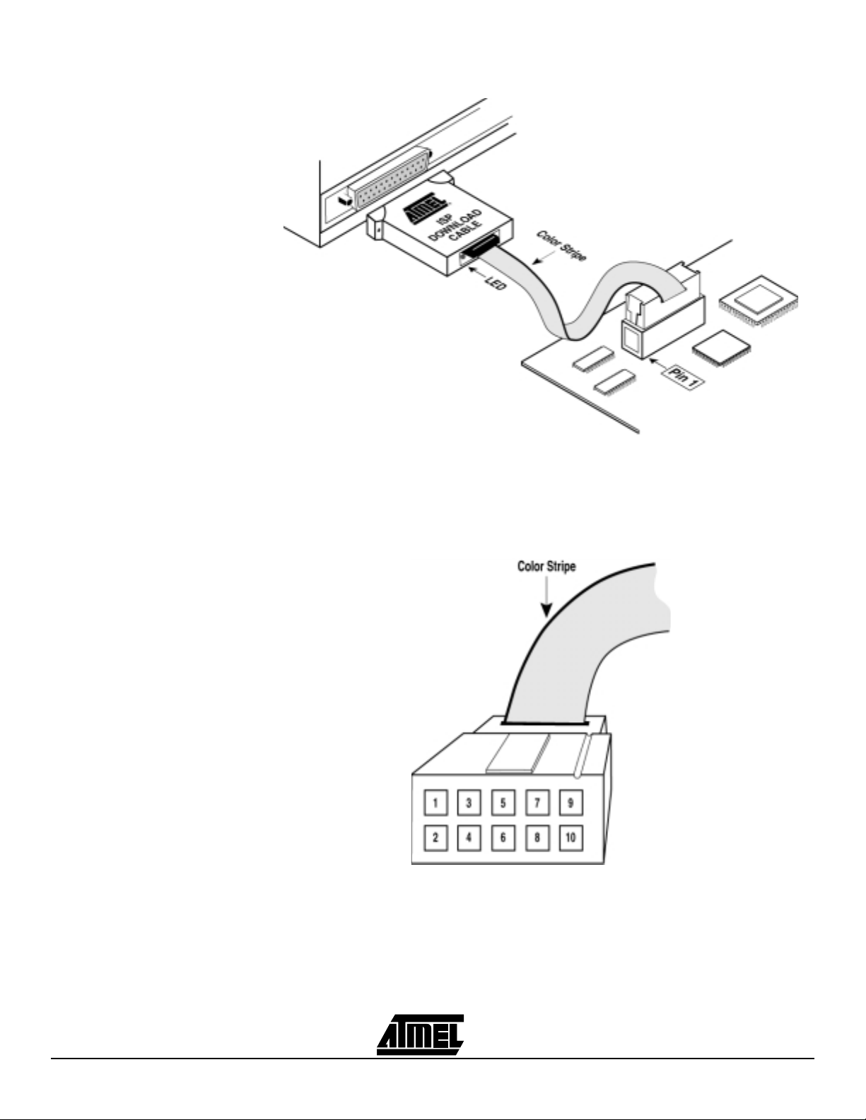
4.3 Atmel-ISP Cable The Atmel-ISP cable connects between the parallel port of your PC and the 10-pin
JTAG header on your circuit board or the Atmel-ISP board. The power-on LED on the
25-pin male connector housing indicates that the cable is connected properly. Make
sure this LED is turned on before using the Atmel-ISP software.
The Atmel-ISP cable consists of a 25-pin male connector, which connects from the parallel port to a 10-pin female header connector. The female header connector connects
to the male 10-pin JTAG header on the ISP circuit board. The color stripe indicates the
orientation of Pin 1 on the header connector. Since the cable is not polarized, use the
color stripe as a guide to assure that the female header connector is properly oriented
when it is attached to either board. See Figure 4-5 for the correct orientation.
If you are attempting to program the ATF1500ASV low-voltage devices, you need to use
Rev. 4 or later of the Atmel-ISP cable. This and later revisions will support both the
ATF1500ASV and AS devices (3V and 5V, respectively). Earlier revisions of the cable
only support the ATF15xx (5V) devices.
The new revisions (Rev. 4 or later) of the cable have built-in circuitry that automatically
detects the supply voltage from your JTAG header and is able to adjust its programming
voltage levels accordingly to handle either AS or the ASV device programming.
Atmel ATF15xx Family: ISP Devices User Guide 4-5
Page 29
Atmel-ISP Hardware
Figure 4-5. Atmel-ISP Cable Connection to ISP Hardware Board/Circuit Board
Figure 4-6 shows the pinout for the 10-pin female header on the Atmel-ISP cable. The
pinout on the 10-pin male header on the PC board (if used for ISP) must match this
pinout.
Figure 4-6. Atmel-ISP Download Cable 10-pin Female Header Pinout
Note: Your circuit board must supply V
and GND to the Atmel-ISP cable through the
CC
10-pin male header.
4-6 Atmel ATF15xx Family: ISP Devices User Guide
Page 30

Atmel-ISP Hardware
The dimensions for the 10-pin male header that is mounted on ISP board are shown in
Figure 4-7, and Figure 4-8 shows the pinout for this 10-pin male header.
Figure 4-7. 10-pin Male Header Dimensions
Top View Side View
0.100
All dimensions are in inches
Figure 4-8. 10-pin Male Header Pinout
TCK
TDO
TMS
NC
TDI
1
3
5
7
9
0.100
10
0.025 Sq.
0.235
2
GND
4
VCC
6
NC
8
NC
GND
The Atmel-ISP cable is subject to hardware revisions from time to time as Atmel
improves its performance and adds new features. Always try to use the latest revision of
the Atmel-ISP cable to program Atmel ISP devices. The revision number is written on
the cable shell.
Atmel ATF15xx Family: ISP Devices User Guide 4-7
Page 31

Atmel-ISP Hardware
4-8 Atmel ATF15xx Family: ISP Devices User Guide
Page 32

Section 5
Getting Started
5.1 In-System
Programming
Procedure
5.1.1 Setting Up the
Atmel-ISP Board
Before you can use the Atmel-ISP software, you will need to make sure that none of the
ISP devices on your circuit board is using the JTAG port pins for logic I/O functions.
Atmel recommends that you erase all devices before inserting them on your circuit
board.
Note: Atmel ships all ISP devices in a bulk-erased state, which enables the JTAG
interface by default. Therefore, all Atmel devices are initially shipped ISP-ready
and are ready to be programmed with the Atmel-ISP software.
If you are using the Atmel-ISP software with your circuit board, skip the next section and
proceed to “Setting Up Your Target System”.
After completing the instructions in this section, skip the “Setting Up Your Target System” section and proceed to “Running the Atmel-ISP Software”.
1. Insert an erased Atmel ISP device into the Atmel-ISP board socket. If you are not
sure if a device is erased, erase it on an external device programmer before
inserting it into the ISP board. If you are programming a non-84-pin PLCC
device, you must insert the appropriate daughter board into Socket 2 of the ISP
board and then insert the ISP device into the socket on the daughter board.
2. Plug an Atmel AC/DC adapter into the 9V DC power connector (J8) on the ISP
board. You can also use a 9V battery to power the ISP board.
3. Plug the 10-pin female connector on the Atmel-ISP cable to the 10-pin male
header (J5) on the ISP board. Ensure that the 10-pin connector is oriented
correctly.
4. Power-up the Atmel-ISP board by flipping switch SW3 on the ISP board towards
the power connector. When power is turned on, the ISP board power-on LED
(D3) will be illuminated.
5. Connect the 25-pin connector on the Atmel-ISP cable to the PC’s parallel port.
Atmel ATF15xx Family: ISP Devices User Guide 5-1
Rev. 1936A-07/01
Page 33

Getting Started
5.1.2 Setting Up Your Target System
Steps 1 and 2 below must be hardwired on your circuit board. These circuit modifications must be made to your design before you can proceed with any ISP operations.
1. Make sure all JTAG ISP devices on your circuit board are connected to a 10-pin
male JTAG header. Figure 4-8 on page 4-7 shows the JTAG header pinout. All
JTAG port pins must originate and terminate on this header.
2. Connect the JTAG port pins (TCK, TDI, TMS, TDO) between the Atmel ISP and
non-Atmel ISP devices together on your circuit board. All JTAG ISP devices must
be connected to form a JTAG chain. Figure 1-1 and Figure 1-2 on page 1-3 show
how to configure single- and multiple-device JTAG chains on your circuit board.
3. Solder or insert (if you have device sockets) the Atmel ISP devices on your circuit
board. Make sure they are either erased or not programmed with logic that uses
the JTAG port pins for logic I/Os. If the parts are configured in this way, they cannot be programmed via ISP. Atmel recommends that you solder erased Atmel
ISP devices on your circuit board first since they are ISP-ready when erased. If
you are unsure whether a device is erased, erase it with an external device programmer before using it in your target system.
4. Power up your circuit board.
5. Connect the Atmel-ISP cable from your PC’s parallel port to the 10-pin header
connector on your circuit board. Make sure the 10-pin header connector is oriented correctly on the hardware board, and the LED on the 25-pin connector
housing of the Atmel-ISP cable is illuminated.
6. You are now ready to run the Atmel-ISP software.
5.1.3 Running the
Atmel-ISP Software
5.1.3.1 Setting Up the
Chain File
The Atmel-ISP software must be installed on your PC before you can run it. When it is
successfully installed, the Atmel-ISP Program and Help icons are automatically created.
1. Double-click on the AT M I S P icon to start the Atmel-ISP software.
2. If a chain file has been previously saved, the software will automatically load in
this chain file and the Atmel-ISP main menu will be displayed.
3. Otherwise, the software will display a dialog box prompting you to enter the number of devices in you JTAG chain. This will occur immediately after the software
is invoked. Either enter a number or select Cancel. If you select Cancel, the
Atmel-ISP main menu will be displayed and you’ll need to follow the steps below
to create a chain file.
1. From the File menu, click once on New. The software will display a dialog box
prompting you to enter the number of devices in your JTAG chain.
Note: Step 1 is unnecessary if you followed step 3 above. If you are using ISP soft-
ware with an ISP board, you must select 1 for the number of devices in your
JTAG chain. Selecting a value other than 1 or attempting to program more than
one device on the Atmel-ISP board may cause an error. You can program multiple ISP devices only with a custom target system.
2. After entering the number of devices, the Device Properties dialog box will
appear. This dialog box will reappear for each device you have defined in your
JTAG chain.
3. Under Device Type, enter the Atmel ISP device type you want to program.
4. Under JTAG Instruction, enter the programming operation you want to perform.
Click on the down arrow once for a list of options.
5-2 Atmel ATF15xx Family: ISP Devices User Guide
Page 34

Getting Started
Note: Non-Atmel ISP devices in your JTAG chain must have the Bypass instruction
selected. If the non-Atmel ISP device does not have an IDCODE register, you
must also uncheck the IDCODE register box selection for that device. Furthermore, the JTAG instruction width needs to be changed accordingly if the nonAtmel ISP device does not have a 10-bit JTAG instruction width. All Atmel PLD
ISP devices have 10-bit JTAG instruction width, and 10 is the default width.
5. After selecting the ISP operation, if you want to execute a Program/Verify, Verify,
Program/Verify/Secure or Load operation, you must enter a JEDEC file name.
Click on Browse to allow you to specify the subdirectory where the JEDEC file is
located. If you are performing an Erase, Secure, Verify Secure, Blank Check
and/or Bypass operation, you are not required to specify a JEDEC file.
6. Click on OK to exit the Device Properties dialog box for that specific device.
The Chain File window will be displayed, showing the ISP operation selected for
the device.
7. Repeat steps 2 to 6 for each device in the JTAG chain.
8. In the File menu, click once on Save. The software will prompt you to save the
information you enter as a chain file name. Enter the file name and click OK. To
recover this information at a later time, you can reload this file by using the Open
command from the File menu.
9. From the View menu, click once on Chain File. This allows you to view the information you have entered with the software to describe your JTAG chain. Verify
that the information is correct. If you need to change it, see the Edit menu com-
mand. Under this menu, you can add, edit and remove devices from an existing
JTAG chain. Atmel-ISP versions V2.99 and later have an option that allows you
to edit, add and/or remove devices in your chain by just double-clicking the chain
file.
5.1.3.2 Executing ISP on Atmel ISP Devices
Before executing ISP operations, the number and order the devices are configured in
your JTAG hardware chain must match both in number and order on your chain file. If
the chain file information does not match your JTAG hardware configuration exactly, the
ISP software will generate an error when it executes your chain file.
Note: When performing ISP operations on multiple devices, you cannot mix different
operations for different devices. For example, you cannot erase one Atmel ISP
device and program another at the same time. You can, however, erase several
devices simultaneously. You can also perform a programming operation on one
device, exclusive of all others. This is done by placing all devices unaffected by
the ISP operation in the Bypass mode.
From the Atmel-ISP software main menu, click once on Process. Select Run. The
Atmel-ISP software will execute the ISP operations specified in the chain file. The
Progress dialog box will be displayed. This box will indicate the percentage completion
for the ISP task as it is being executed. If the operation was executed successfully, the
Success dialog box will be displayed. If the ISP operation was not successful, the Error
dialog box will be displayed for the appropriate device. For example, if the device fails to
program, the Program Fail message will be displayed.
Atmel ATF15xx Family: ISP Devices User Guide 5-3
Page 35

Getting Started
5.2 Using
ByteBlaster/Byte
BlasterMV
Cable
with Atmel ISP
Devices
5.3 Creating SVF Files
If you want to use the ByteBlaster/ByteBlasterMV cable, first go to the main menu.
Select the Process menu, then choose Options. Two notices will appear: one asks
whether you want to save your programming data in a SVF (Serial Vector Format) file;
the second notice asks whether you want to use the ByteBlaster cable. If you select No
to SVF format and Yes for ByteBlaster cable, the ISP software will use this cable to
download ISP operations to the devices on your circuit board. Make sure that your ByteBlaster/ByteBlasterMV cable is connected to either your circuit board or ISP board. The
options you specified will take effect when you re-execute the Process..Run command.
To switch the cable type back to the Atmel-ISP cable, go to the main menu, select the
Process menu, and choose Options. Select No again to SVF format. The second notice
will be different from before and it will ask if you want to use the Standard cable. If you
select Yes, then the cable type will be switched back to the Atmel-ISP cable type.
Note: Check the chain file first before executing any operation. The chain file should
indicate the parallel port setting used and if the ByteBlaster cable type is
selected. If it does not, then check to ensure that the software communicates
with your board. Refer to Section 7, “Troubleshooting” for more information.
The Atmel-ISP software can create Serial Vector Format (SVF) files that can be used to
execute ISP operations on automated test equipment (ATE). The Atmel-ISP software
supports two revisions of the SVF specification: Revs. C and D. Revision C is needed
to support Jam
Rev. D is preferred.
™
programming. Rev. C or D can be used by the ATE tester; however,
To create an SVF file, perform the following procedure:
1. Create the chain file in the Atmel-ISP software.
2. When you are done, go to Process..Options.
3. At the notice “Write to SVF file instead of LPT port?”, select Ye s .
4. At the notice “Does the Target System Support SVF Rev. D?”, select either Ye s
for Rev. D, or No for Rev. C.
5. The Create SVF File dialog box will open. Enter the file name and click OK.
6. At the notice “Use STATE RESETS in SVF File”, select either Ye s or No. If you
are just programming Atmel devices, it is recommended that you select Ye s .
7. Go to Process..Run to execute the ISP operations.
8. Exit the Atmel-ISP software.
Note: The ISP software requires you to exit the software before the SVF file is written
to disk. Trying to open an SVF file while the software is running will display a file
of null (0 bytes) size.
5-4 Atmel ATF15xx Family: ISP Devices User Guide
Page 36

Getting Started
5.4 Creating Jam Files
5.5 Creating PCF Files
The Atmel-ISP software and the competitor’s SVF2JAM translator allow you to create
Jam files that can be executed on the competitor’s Jam player. It should be noted that
any of the command line options in the Jam player except the port address are not available for Atmel devices. Also, you must use the ByteBlaster/ByteBlasterMV
execute Jam files. Each Atmel Jam file can only execute specific programming operations that are embedded into that file.
Please refer to the application note “Creating Atmel JAM/JBC File(s) for the ATF1500AS
Device Family” for further details on how to create Jam files for Atmel ISP devices.
If you are using the Hewlett-Packard HP3070 Series of ATE testers to program your
Atmel ISP devices, you’ll need the HP Pattern Capture Format (PCF) files. This PCF file
can be created by converting an SVF file generated by the Atmel-ISP software into a
PCF file using the SVF2PCF utility. Please refer to the “In-System Programming of
Atmel ATF1500AS Devices on the HP3070” application note for further information on
this subject. Both the application note and the SVF2JAM utility are available for download from Atmel’s web site and BBS.
cable to
Atmel ATF15xx Family: ISP Devices User Guide 5-5
Page 37

Getting Started
5-6 Atmel ATF15xx Family: ISP Devices User Guide
Page 38

Section 6
JTAG ISP Guidelines
This section describes important guidelines and information about ISP that all users
must pay attention to when performing ISP operations on Atmel ISP devices.
1. Make sure all ISP devices on your circuit board are erased before programming.
• To prevent the use of the JTAG port pins by any of the ISP devices.
• This will enable the JTAG port.
• All Atmel ATF15xx devices are shipped in the erased state so that they are ISP-
ready.
2. Make sure the red LED on the back of the Atmel-ISP cable is on when
programming.
• To ensure that the ISP cable is connected properly.
3. Verify that the correct ISP cable is used.
• Atmel-ISP software defaults to using the Atmel-ISP cable.
• Must change cable type if using ByteBlaster/ByteBlasterMV cable.
4. If a parallel cable is used to connect the ISP cable to the PC’s parallel port, make
sure the parallel cable being used is 6 feet long or less.
• Parallel cable longer than 6 feet might introduce communication problems
between the ISP cable and the parallel port.
5. When using Atmel-ISP cable, make sure that the cable is connected to the
ISP\target board before powering up the ISP\target board. Once the ISP\target
board is powered up and the LED on the back of the ISP cable is turned on, then
connect the other side of the ISP cable to the PC’s parallel port.
• To eliminate possible communication problem.
6. Run Self-Calibrate or Manual Calibration if the software is having problems communicating with the JTAG device hardware chain.
• Self-Calibrate and Manual Calibration allow the user to reduce the transfer
speed of the JTAG signals from the PC’s parallel port to the JTAG device chain.
7. Make sure your parallel port settings are configured correctly.
• The ISP software may have problems running on PCs with Auto mode configu-
ration for parallel port.
• Change your BIOS port settings to either ECP or EPP mode.
• Confirm your port address setting before using the software.
• Default settings are: 0378H for LPT1; 0278H for LPT2.
• Other port addresses must be entered manually.
Atmel ATF15xx Family: ISP Devices User Guide 6-1
Rev. 1936A-07/01
Page 39

JTAG ISP Guidelines
To set Parallel Port mode to ECP or EPP in Windows 3.x:
1. Reboot or turn on PC and access CMOS Setup.
2. When the screen displays the message “Press key for Setup”, press the
appropriate key. Some notebooks will require you to press [F2] or the
[Delete] key. Others may require you to press [Ctrl]-[Alt]-[S] keys
simultaneously.
3. When the setup screen appears, select Peripheral selection. You may need
to scroll through all pages to find the Parallel port mode selection.
4. Set the Parallel Port mode to ECP or EPP.
5. Save setup and exit CMOS Setup (most likely, press the [Esc] key).
Once Windows boots, run the ATMISP program. Make sure the ISP board power is
turned on before you run the program. If the program does not run, check the Control Panel to make sure that the Parallel Port mode is set to ECP or EPP.
To set Parallel Port mode to ECP or EPP in Windows 95/98:
1. Select the Control Panel from the My Computer window.
2. Select System icon and then select Device Manager option.
3. Double-click on Ports (COM & LPT). All the ports will appear under the
option.
4. Select Printer Port (LPT) and click Properties.
5. Select Drive option and click on Change Drive option.
6. Click on Show all devices. All the printer port modes will be displayed in the
right column.
7. Select ECP Printer Port mode.
Click on OK (3 times to get out of System Properties window). Windows may
prompt you to reboot your PC. Click OK.
8. Switch 4 of SW2 is used to select either Device #1 (84 PLCC) or Device #2
(daughter board) as the target device.
• When Switch 4 is off, Device #1 (84-PLCC socket) will be the selected target
device.
• When Switch 4 is on, Device #2 (daughter board) will be the selected target
device.
The ISP board cannot program both Device #1 and #2 simultaneously.
9. ISP uses JTAG interface.
• Optional internal pull-ups on TMS and TDI can be used. Pull-ups are required
on TMS and TDI by the JTAG standard.
• Must select correct device types in Atmel-Synario and Atmel-WinCUPL to
enable JTAG TAP.
10. ISP is available when the part is in Pin-controlled Power-down mode or when
“low power” device is asleep.
11. Device state after interruption of ISP:
• If ISP is interrupted, all I/O pins are tri-stated regardless of the state of the pin-
keeper circuits.
• Prevents partially programmed device from causing bus contention with other
devices on circuit board.
6-2 Atmel ATF15xx Family: ISP Devices User Guide
Page 40

JTAG ISP Guidelines
12. During ISP programming, all I/O pins are in one of the following conditions:
• High-impedance state:
– When a blank/erased device is programmed
– When a device is reprogrammed with the pin-keeper circuits disabled
– Prevents bus contention with external devices interfacing with Atmel device
on the circuit board
• Weakly latched to the previous state:
– When a programmed device is reprogrammed with the pin-keeper circuits
enabled
– I/O pins keep previous logic levels, prior to ISP
– Prevents ISP from affecting the operation of other devices on the system
board
13. Don’t use multiple JTAG chains on one board.
• Devices may interact between different JTAG chains.
• Board is functional only when all devices in all JTAG chains are programmed
successfully.
• If programming fails for at least one device in a chain while other JTAG chains
were successfully programmed:
– Either Atmel or other devices on board can be damaged.
• Possible bus contention problem for tri-stateable outputs
– System board operational state is undefined.
• Incorrect functional operation may occur
Solution: Use one JTAG chain to link all devices on the board.
14. Avoid long (+5 devices) JTAG devices chains.
• If you must generate a long chain, buffer the TMS, TCK signal between devices.
– Schmitt trigger buffers preferred
• Buffers reshape rise times on TMS and TCK signals.
15. Buffer all JTAG pins directly at the header.
• Alternate approach to handling long JTAG chains
• Assures clean rising edges on all JTAG signals
16. Use a slower TCK frequency.
• TCK skew may cause setup/hold violations on long device chains for faster
clock frequencies.
• Slower frequency signals are less subject to transmission line effects (ringing,
overshoot), which can cause programming problems.
• Slower signal frequency generates less noise/crosstalk on cable.
17. Terminate JTAG signals at header.
• Both active and passive termination are acceptable. However, passive termina-
tion is preferred.
• Reduces ringing due to long cable/PCB trace lengths.
• Termination is most critical for TMS and TCK.
Atmel ATF15xx Family: ISP Devices User Guide 6-3
Page 41

JTAG ISP Guidelines
18. Do not insert active circuits between JTAG header and the JTAG devices in
chain.
• If active circuit malfunctions:
– May cause programming/verify problems
• TDO is important.
– Errors on this output cause verify problems during ISP operation
19. Don’t create mixed-voltage device JTAG chains.
• This is a JTAG chain that has both 3V and 5V devices.
• 3V outputs may not drive 5V (CMOS-compatible) inputs on other devices on cir-
cuit board. Programming problems may occur for 3V devices.
6-4 Atmel ATF15xx Family: ISP Devices User Guide
Page 42

Section 7
Troubleshooting
7.1 ATMISP Messages
7.1.1 Error Messages Failed to Save Chain File
This section is useful in resolving any problems that may arise when executing ISP
operations using the Atmel-ISP software. Messages generated on-screen are further
classified into error messages, warning messages and notices.
The software was unable to write the .chn file to disk. Possible reasons for this error are:
The file is a read-only file.
The file directory to be written to does not exist or cannot be accessed.
An operating system or hardware error. For example, no floppy disk in drive.
Chain file has wrong number of devices
The number of devices in your chain does not match the number of devices the ISP software detected in your JTAG hardware chain. Edit the open chain file using the Delete or
Add Device command or create a new one to make sure the device number matches.
Conflicting Instructions in Chain File
This error is generated when you have two or more different ISP instructions (except
Bypass) in your multi-device chain. For example, if you have a 2-device chain, and
you’re trying to program the first part while verifying the second. The workaround for this
error is described in the following paragraphs.
In the previous example, create a chain file that programs the first device while putting
the second into Bypass. Then create a new chain file that puts the first device into
Bypass while verifying the second device. This process can be repeated in a similar
manner for larger device chains.
If you are trying to program the above chain using an ATE tester, you can create the first
chain file and generate the SVF file. At the prompt “Close SVF and Start Another”, select
No and create the second chain file. Select SVF output format to create the SVF and
now select Yes at the “Close SVF and Start Another” prompt. The contents of the SVF
file for the second chain file will be appended to the first. After you exit the software, one
SVF file that executes both chains will be saved. The same process could be repeated
for larger JTAG chains.
Atmel ATF15xx Family: ISP Devices User Guide 7-1
Rev. 1936A-07/01
Page 43

Troubleshooting
Chain File has <n> devices System has <m> Devices
If the Atmel-ISP software detects a mismatch between the number of device(s) you
have specified in your chain file and the actual number of device(s) on your JTAG hardware chain, this error will be displayed. The easiest workaround for this would be to edit
your chain file accordingly to match the number of devices actually on your hardware
board.
Another cause for this error occurs when the IDCODE box in the Atmel-ISP software
JTAG Properties dialog box for each device is not checked. Versions 2.77 and later of
the ISP software will warn you about this, but earlier versions may not. When this box is
not checked, the Atmel-ISP software may incorrectly read out the manufacturer ID
codes from all the devices in the chain and therefore may detect the wrong number of
devices.
It is highly recommended that you also download the latest release of the Atmel-ISP
software from the Atmel web site or BBS.
Read Chain File
The software was unable read the chain file specified. This error usually occurs if the file
you are trying to load is not a chain file.
Problems with reading JEDEC files
This error occurs when the ISP software was unable to read the JEDEC from the directory you have specified. Possible reasons for this error:
The JEDEC file name you have specified does not exist.
The subdirectory from where the JEDEC file is loaded does not exist.
An operating system error. For example, loading the JEDEC file from a floppy disk in
drive A: when there is no diskette in the drive.
Problems with saving JEDEC files
This error can occur when executing a Load operation on the ISP software and specifying a JEDEC file name to save the loaded fuse data. Possible reasons for this error:
The subdirectory where the JEDEC file is to be saved does not exist.
An operating system error, such as saving the JEDEC file to a floppy disk in drive A:
when there is no diskette in the drive.
Chip <number> Fails
This error is generated when the chip specified by <number> fails any of the programming operations such as Program, Secure, Verify, Load, Erase or Blank Check.
<number> specifies which chip actually failed. The number depends on the chip location
in the JTAG chain. For example, Chip 1 would be the first chip in the chain; Chip 2, the
second, and so on.
7-2 Atmel ATF15xx Family: ISP Devices User Guide
Page 44

Troubleshooting
Secure Verify Fail
This error occurs when the ISP software is unable to verify that a device is secured in
your JTAG chain. This can occur due to the following reasons:
You have more than one device in your chain, and the other devices are not placed in
the Bypass mode.
The device you are trying to verify was already secured with a JEDEC file that either
disables the JTAG port or uses the JTAG port pins.
No Devices Found
This error is generated when your JTAG hardware chain is incorrectly configured. Possible reasons for this error are discussed below:
1. Problem: The power to your circuit board was accidentally turned off.
Solution: Make sure your circuit board is powered on before running the software.
2. Problem: Your circuit board does not contain an Atmel ISP device(s).
Solution: Make sure at least one Atmel ISP device is inserted in your circuit board.
3. Problem: No cable is connected between the PC’s parallel port and the 10-pin
JTAG header on your circuit board.
Solution: Make sure you connect either the Atmel-ISP cable or ByteBlaster/MV
cable (if the correct software option is enabled) between the PC’s parallel port and
your circuit board.
4. Problem: The Atmel-ISP cable is being used, but it is connected in the wrong
orientation on the 10-pin JTAG header on the hardware board.
Solution: Make sure the red LED on the back of the Atmel-ISP cable is illuminated
when it is connected to the hardware board. If is it not illuminated, the cable is not
connected properly.
5. Problem: The Atmel-ISP software does not work when the cable is first connected to the PC before being connected to the target board.
Solution: The Atmel-ISP cable contains active components that are powered from
the circuit board. Inputs to the active components are driven by the parallel port.
Connecting the cable to your PC first can cause the inputs of the active component
to be driven before the active components in the cable are powered up. This may
affect the operation of the ISP cable. Connect the 10-pin header of the ISP cable to
your target board first and power it up. Then connect the 25-pin DIN connector to
your PC.
6. Problem: The Atmel-ISP software has been configured to use the Atmel-ISP
cable but you are using the ByteBlaster/MV cable, and vice versa.
Solution: Change your ISP software configuration for the cable that you want to
use.
7. Problem: A device programmed on your circuit board has the JTAG port disabled or is using the JTAG port pins as logic I/Os.
Solution: Remove the device from your circuit board, erase it on an external device
programmer and reinsert it onto your circuit board.
Atmel ATF15xx Family: ISP Devices User Guide 7-3
Page 45

Troubleshooting
8. Problem: The Atmel-ISP software detects the devices in your hardware chain
but reports the wrong number of devices.
Solution: Check whether any device in your JTAG hardware chain was programmed with a JEDEC file that buffers the TDI pin to the TDO pin. Remove this
device from your circuit board and erase it using an external device programmer.
9. Problem: The device type you specified in your chain file is incorrect. The
Atmel-ISP software should report this error.
Solution: Make sure to specify the correct device type in the chain file.
10. Problem: Your JTAG hardware chain is incorrectly configured on your circuit
board.
Solution: Your JTAG hardware chain must be hardwired correctly on your circuit
board before you can implement ISP. See also “Setting Up Your Target System” in
Section 5, “Getting Started”, for the correct setup of your JTAG hardware chain.
11. Problem: Yo u r P C ’s parallel port is not connected to LPT1 or has the wrong port
address.
Solution: Go to File..Port Setup to change to the correct LPT port setting.
12. Problem: You have specified the correct parallel port address but the ISP software still fails to communicate with your circuit board.
Solution: Change your parallel port setting in BIOS to either the ECP or EPP mode.
If you are using Windows 3.x or Windows 95/98, you can also configure Windows
to select the correct ECP or EPP port driver. For details, contact Atmel PLD
Applications.
13. Problem: The ISP software communicates on some PCs but not others. An
earlier version works but the newer version does not.
Solution: Try to use the Self-Calibrate or Manual Calibration options. These options
can be used to slow down the transfer speed the software uses when communicating between your PC’s parallel port and the hardware. The Atmel-ISP software may
not be able to communicate reliably on some PCs at faster parallel port transfer
speeds. The Self-Calibrate and Manual Calibration options adjust the transfer speed
the software uses so it can reliably communicate between the PC’s parallel port and
your hardware. Older versions of the software communicate at a slower transfer rate
(approximately 50% slower) than newer versions.
14. Problem: You are running the ISP software on Windows NT and the software
fails to communicate with your hardware.
Solution: You need a different version of the ISP software (ATMISPNT) to be able
to run on Windows NT 3.x and above. The Windows NT version of the Atmel-ISP
software is also available on Atmel’s web site and BBS for download.
15. Problem: You have not connected the supply voltage and GND of your target
system to the appropriate VCC and GND pins, respectively, on the 10-pin JTAG
header(s) on your board.
Solution: Wire up the VCC and GND pins on the JTAG header to their respective
VCC and GND buses on your board.
Note: Contact Atmel PLD Applications if none of the above suggestions appear to
resolve this error.
7-4 Atmel ATF15xx Family: ISP Devices User Guide
Page 46

Troubleshooting
Invalid Chain File
You have attempted to load a chain file, which the ISP software does not recognize. Use
the File.. New command to create a new chain file with the ISP operations you want to
perform and re-save it under your old file name.
Invalid Device ID
The Atmel-ISP software reads an incorrect manufacturer silicon device ID for an Atmel
ISP device on your circuit board. If any Atmel device has an invalid ID, you can still perform ISP operations on it by using the hidden ID Check Override command. However, it
is not recommended to override the device ID check feature.
For example, if you created a 2-device chain with ATF1508AS and ATF1504AS devices
but you actually have two ATF1508AS devices on your board, this error will be generated. It is not recommended that you override the IDCODE Check in this case.
The same error would occur if you have two ATF1508ASV devices in your chain file but
there are actually two ATF1508AS devices on your board. The workaround is to edit the
chain file accordingly to match the device types on your board.
Contact Atmel PLD Applications if you encounter this error with any Atmel ISP device(s).
Device number not valid
This error normally occurs when you are using the Edit, Add or Delete Device commands and specify the wrong device number. The ISP software can flag the wrong
number if you specify a number greater than the actual number of devices already specified in your chain file. If you have a blank chain file, you cannot specify any device
number as no device information exists yet. In this case, edit the existing chain file to
add at least one device.
JEDEC file <Filename> disables the JTAG port on Chip <number>
The JEDEC <filename> you have specified will program the appropriate chip <number>
with logic that either disables the JTAG port or uses the JTAG port pins as logic I/Os.
The Atmel-ISP software generates this error because you cannot reprogram this chip
<number> or any other device in your JTAG hardware chain using the ISP software.
If this device is programmed, the only way to reprogram using ISP is to remove it from
you circuit board, erase it using an external device programmer and reinsert it in your
circuit board. If you still must program this chip, there is a JTAG port override option
available on the Atmel-ISP software.
JEDEC file not specified
You have specified an ISP operation that requires a JEDEC file to be specified. If you
are trying to execute a Program, Verify, Program/Verify or Program/Verify/Secure operation on any device in your chain file without a JEDEC file, you will see this error
message. Edit your chain file using the Edit Device command and specify a JEDEC file.
Both 5V and 3V devices in Chain File
This error occurs when you create a chain file that has both ASV (low voltage) and AS
devices (standard power).
This is currently not allowed by the Atmel-ISP software. You must create a chain that is
either all 5V or 3V devices. Creating a mixed-voltage device chain file may create functional problems on your board if you have 3V devices that must handle 5V inputs. Also
Atmel ATF15xx Family: ISP Devices User Guide 7-5
Page 47

Troubleshooting
programming a 5V device at 3V, or vice versa, is not recommended. Either combination
could cause programming problems if you have a mixed-voltage device chain file.
If you still must program a mixed-voltage device chain, there is an override option available that will disable this error.
This is a 3V system with 5V devices
This error occurs if you have a 3V supply on your target system but are using 5V
device(s) on your board. If the Atmel-ISP software detects a 3V supply on the JTAG
header and a 5V device ID is read out from at least one device in your hardware chain,
then it will generate this error.
You can prevent this error by either editing your chain file accordingly to select 5V
device types and/or removing the 5V devices from your board and replacing them with
3V devices.
If you still must program 5V devices with a 3V supply, there is an override option to disable this error.
This is a 5V system with 3V devices
This error occurs if you have a 5V supply on your target system but are using 3V
device(s) on your board. The Atmel-ISP software detects the supply voltage on your
board’s JTAG 10-pin header and reads the IDCODE of the Atmel device(s) in your hardware chain. If it detects a 5V supply on the JTAG header and a 3V device ID is read out
from at least one device in your hardware chain, then it will generate this error.
You can prevent this error by either editing your chain file accordingly to select 5V
device types and/or removing the 3V devices from your board and replacing them with
5V devices.
If you still must program 3V devices with a 5V supply, there is an override option to disable this error.
7.1.2 Warning Messages Chain File already exists
You are attempting to overwrite an existing chain file. This warning occurs when you are
using the Chain File Save/Save As command. If you select Yes on this warning message, the chain file will be overwritten; otherwise, the command will be aborted.
Chain File Changed
This warning occurs when you exit the ISP software without saving your chain file. It will
also occur if you edit your chain file and exit the software without saving it. If you select
Yes, the ISP software will prompt you for a file name to save the chain file. Otherwise, its
contents will be lost.
Atmel Devices need the IDCODE box checked
The IDCODE box is a JTAG convention that indicates whether a JTAG device has a
32-bit Manufacturer ID register between its TDI and TDO pins that contains the device
ID. All Atmel devices have this register.
Some devices by other vendors (such as TI Boundary Scan Logic Chips) don’t have a
manufacturer IDCODE register. So the 1-bit Bypass register appears between TDI and
TDO by default. If these devices are in your JTAG HDWR chain, then IDCODE box for
them must not be checked.
7-6 Atmel ATF15xx Family: ISP Devices User Guide
Page 48

Troubleshooting
The reverse is true for devices that have an ID code (such as Atmel ISP devices). The
IDCODE box must be checked for them.
If the IDCODE box is in the wrong state, it will affect the bitstream that the software actually sees from your JTAG hardware chain versus the bitstream it expects to see. The
result can be either incorrect programming and/or incorrectly detecting the actual number of JTAG devices on your board.
If you attempt to uncheck the IDCODE box for an Atmel device in your chain, you will
receive this warning message with Atmel-ISP software, version 2.77 and higher. The
state of the IDCODE box, if it is unchecked, will also be indicated in your chain file.
IDCODE Checking is now <ON/OFF>
This warning occurs if you attempt to override the manufacturer ID check on the device
using the [Shift]-[Alt]-[L] key sequence. Selecting OK confirms the state of whether
IDCODE checking is either on or off. The Atmel-ISP software defaults to having the
IDCODE checking turned on. It will remain on until the hidden key sequence above
turns it off. It will remain off until turned on again by reentering the same key sequence.
JTAG Port Checking is now <ON/OFF>
This warning occurs if you attempt to override the “JTAG Port Pin” error by using the
[Shift]-[Alt]-[J] key sequence. This error occurs when your design is using the JTAG port
pins for logic. Selecting OK confirms the state of whether the JTAG port checking is on
or off. The Atmel-ISP software defaults to having the JTAG port checking turned on. It
will remain on until the hidden key sequence above turns it off. It will remain off until
turned on again by reentering the same sequence. The setting will remain in effect as
long as the Atmel-ISP software is running.
Mixed Voltage Device Checking is now <ON/OFF>
This warning occurs if you attempt to override the “Mixed Voltage Device Check” error
using the [Shift]-[Alt]-[V] key sequence. This warning appears when you are attempting
to program both 3V and 5V Atmel devices in the same JTAG chain.
Selecting OK confirms the state of the mixed-voltage device checking to be either on or
off. The Atmel-ISP software defaults to having the mixed-voltage device checking turned
on. It will remain on until the hidden key sequence described above turns it off. It will
remain off until turned on again by reentering the same key sequence. The setting will
remain in effect as long as the Atmel-ISP software is running.
Security Fuse Verify only Works for 1 Device
This warning message is displayed when you try to verify the security bit for more than
one device. The security bit can only be verified for one device at a time. All other
devices in your hardware chain must be placed in the Bypass mode. If you select Yes to
the Verify Secure command, then one device will be secured. If you select No, the Verify
Secure command will be cancelled.
Note: It is recommended that you select No. Otherwise, you will not be able to deter-
mine which device is actually secured.
Atmel ATF15xx Family: ISP Devices User Guide 7-7
Page 49

Troubleshooting
7.2 Notices Write to SVF instead of LPT port?
The notice appears when you select the Process.. Options command. The ISP software
will ask you if you want to save the programming data to a Serial Vector Format (SVF)
file. If you select Yes, an SVF file is created. Otherwise, the software downloads programming data directly to the Atmel ISP devices on your circuit board. This file is
needed if you want to execute ISP on automated test equipment (ATE) that supports the
SVF format.
The SVF file created will only support ISP operations on Atmel ISP devices. If you need
to program devices from different vendors with a single SVF file or execute JTAG
Boundary Scan Test (BST) operations on an Atmel device, you need to use third-party
JTAG software that supports these features. For more information, contact Atmel PLD
Applications.
Use State Resets in SVF File?
This notice asks whether you want to include a TEST-LOGIC-RESET state in the SVF
programming file. If you are programming just Atmel ISP devices in your JTAG hardware chain, it is recommended that you select Yes. If you are programming Atmel ISP
devices in a mixed-vendor JTAG hardware chain, it is recommended you select No.
Selecting Yes for the latter option causes the Atmel-ISP software to insert TESTLOGIC-RESET instructions within the SVF file. This may cause other vendor devices to
reset when the Atmel SVF file is being executed. In turn, boundary scan, programming
and/or functional operations of other non-Atmel device(s) in your JTAG hardware chain
may be affected. This command, however, will have no effect on Atmel devices.
Selecting No will make sure that the SVF always enters and leaves the JTAG Test
Access Port (TAP) in the RUN-TEST-IDLE state. At a later time, when you want to reset
all of your devices, you can place the TAP into the TEST-LOGIC-RESET state. This
should allow all devices in your chain to reset simultaneously.
Does Target System Support SVF Spec. Rev. D?
This message is applicable if you plan the use the Serial Vector Format (SVF) file generated by the Atmel-ISP software to execute ISP operations on an automated device
(ATE) tester. The SVF specification has several revisions. An earlier revision, Rev. C, is
supported by most ATE and semiconductor vendors. However, it requires you to implement delays for programming operations by modeling them as a specific number in the
JTAG clock TCK periods. The period of the JTAG TCK can be specified in nano- or
milliseconds.
This has some pitfalls, though. If the tester’s clock period is adjusted in the hardware
without an appropriate change in the SVF file, the delay period will be modeled incorrectly. The result is that the device(s) may not be programmed correctly. A later version
of the SVF specification, Rev. D, allows you to model a delay as single time value. For
example, milliseconds. This value is independent of the TCK period used by the tester
hardware. If your tester supports this, then it is the preferred format to use.
In this case, select Yes. A new notice will not appear.
7-8 Atmel ATF15xx Family: ISP Devices User Guide
Page 50

Troubleshooting
Close SVF File and Start Another?
Choosing this command gives you the option to close an SVF file that is already open
and append new ISP operations to it. This command is useful when you want to perform
a different set of ISP operations using the same SVF file. This prevents you from having
to create a separate SVF file for each group of ISP operations you want to perform.
However, if you want to do this, select Yes. Otherwise, select No. Atmel recommends
that you choose Yes here so that you don’t inadvertently create an SVF file that executes more operations than you intended to perform.
If you do select No for this feature, remember to close your SVF file after you have completed appending all the operations you want performed on it.
Enter TCK Period in Microseconds?
This notice assumes that you selected No when you responded to the “Does your Target System Support SVF Spec Rev D?” message. This means that the software will be
creating a Rev. C version of the SVF file, which must specify delays in number of TCK
periods.
You must enter a value for the TCK period at this prompt. The software supports
1-microsecond increments. So just enter only the value.
For example, if you want to enter a 1-microsecond TCK period, just type 1 and select
OK. The software will automatically calculate the number of TCK cycles required to
model any required delays needed when creating the SVF programming file.
Use Standard Cable?
This message will appear if you have originally configured the Atmel-ISP software to use
the ByteBlaster/MV cable or have loaded an existing chain file that has the ByteBlaster/MV cable selected. If you select No, the software will assume you want to
continue to use the ByteBlaster cable. If you select Yes, the software will change to use
the Atmel-ISP cable.
You will have to change your cable accordingly between your PC and your target board
before executing your chain file. Otherwise, you may receive a “No Devices FoundCheck Cables” error.
For ATF1500ASV devices, it is recommended that you use Rev. 4 or later of the
Atmel-ISP cable. This later revision contains special hardware within the cable to support our low-voltage devices. Using an older version of the Atmel-ISP cable may cause
programming problems with ASV devices. The revision number of the Atmel-ISP cable
is written on the shell of the cable.
Use ByteBlaster Cable?
This notice appears after you have executed the Process.. Options command and
selected No for SVF output. The software is asking you whether you want to use the
ByteBlaster cable to execute ISP operations on your target board. If you select Yes,
make sure the ByteBlaster cable is connected to your hardware. Otherwise, the software will require you to use the Atmel-ISP cable.
Atmel ATF15xx Family: ISP Devices User Guide 7-9
Page 51

Troubleshooting
7-10 Atmel ATF15xx Family: ISP Devices User Guide
Page 52

Section 8
Ordering Information
ATDH1150VPC Windows 95/98 ISP Software + Multi-volt Cable
ATDH1151VPC Windows NT ISP Software + Multi-volt Cable
ATDH 1160VPC Multi-volt ISP Board + Multi-volt ISP Cable + Windows 95/98
ISP Software
ATDH 1161PC 44-pin PLCC Adapter Board
ATDH 1162PC 44-pin TQFP Adapter Board
ATDH 1163PC 68-pin PLCC Adapter Board
ATDH 1164PC 100-pin PQFP Adapter Board
ATDH 1165PC 100-pin TQFP Adapter Board
ATDH 1166PC 160-pin PQFP Adapter Board
Note: The ATDH1150PC (5V-only ISP cable) and ATDH1160PC (5V-only ISP board)
are no longer available and they are replaced by ATDH1150VPC and
ATDH1160VPC, respectively.
Contact information for Atmel PLD Applications:
Hotline: (408) 436-4333
E-mail: pld@atmel.com
URL: www.atmel.com
Atmel ATF15xx Family: ISP Devices User Guide 8-1
Rev. 1936A-07/01
 Loading...