

Page 1

1.1 Unpacking the system
Kit contents:
1 ATAVRAUTO100 V1.0 board
1 ATAVRAUTO102 V1.0 board
1 ATAVRAUTO200 V1.0 board
1 ATAVRAUTO300 V1.0 board
1 ATAVRAUTO900 V1.0 board
5 Cables for board connection
1 USB Mini-B to A cable
Section 1
ATAVRAUTOEK1 Getting Started
1 Getting Started
1 Automotive CD-Rom
1 AVR CD-Rom software and technical library
1 Dear customer letter
Note: All boards are shipped with a demo firmware loaded. This guide gives you all
keys to plug and play the ATAVRAUTO evaluation kit demo.
ATAVRAUTOEK1 1-1
7700A–AUTO–06/07
Page 2
ATAVRAUTOEK1 Getting Started
Analyser
ATAVRAUTO102
ATAVRAUTO100
ATAVRAUTO200
ATAVRAUTO300
LIN to CAN
DC Motor
Joystick board
gateway borad
control board
LIN0
LIN1
CAN
USB
to any others LIN no des
to any others CAN nodes
to any others LIN nodes
1
2
GND
VBat
LIN0
LIN1
CANHCANL
MOTA
MOTB
HALLA
HALLB
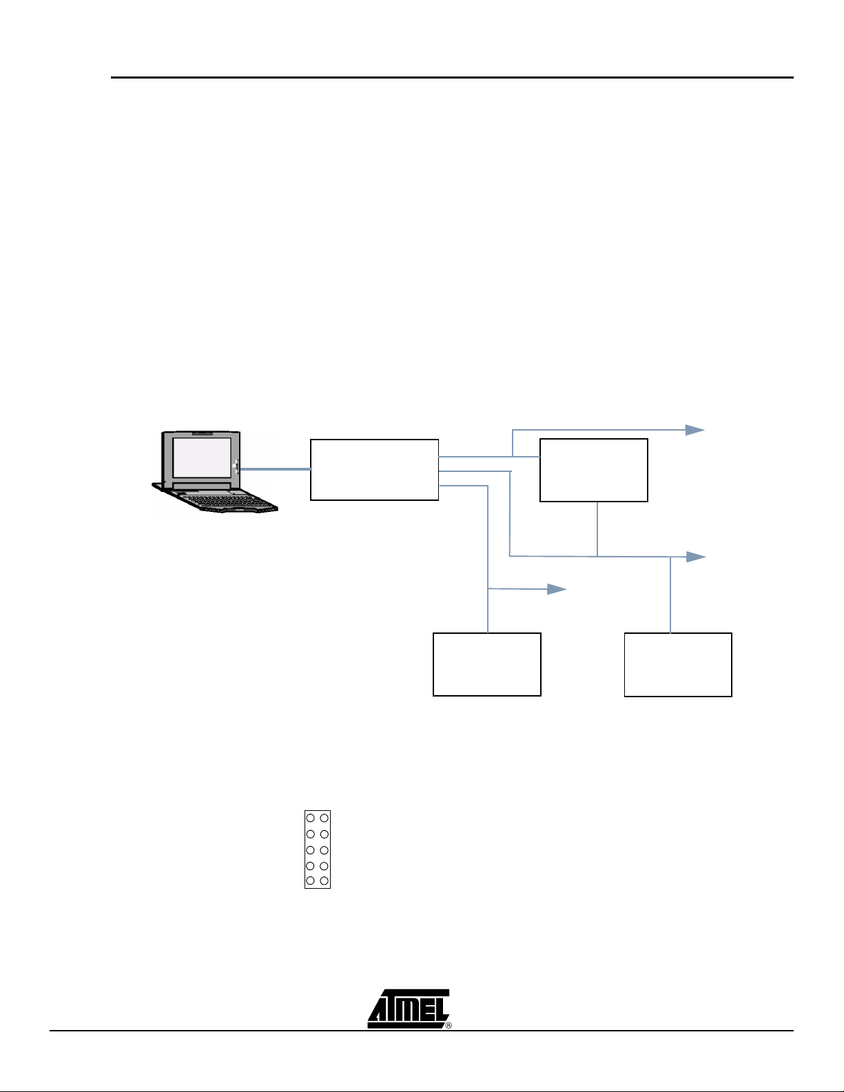
1.2 Overview
The ATAVRAUTOEK1 evaluation kit has been designed to give designers an easy and
fast way to develop automotive applications. The evaluation kit is shipped with a board
used as a vehicle network analyser (ATAVRAUTO102), a gateway between one LIN netwo rk to o n e C AN n e tw or k ( ATAV R A U T O1 0 0 ) , a D C m ot o r co nt ro l b oa r d
(ATAVRAUTO200) and a joystick board (ATAVRAUTO300).
The ATAVRAUTOEK1 evaluation kit is shipped with all boards connected together on
the PCB (as describe in the following schematic):
– The ATAVRAUTO300 board is connected to the ATAVRAUTO102 board via
the LIN0.
– The ATAVRAUTO100 board is connected to the ATAVRAUTO200 and to the
ATAVRAUTO102 boards via the LIN1.
– Boards ATAVRAUTO100 and ATAVRAUTO102 are connected together via the
CAN.
Figure 1-1. Evaluation kit
An 10-pins connector is available on the PCB to access internal signals. The pinout is as
following:
Figure 1-2. 10-pins connector pinout
ATAVRAUTOEK1 User Guide 1-2
7700A–AUTO–06/07
Page 3

ATAVRAUTOEK1 Getting Started
M
GND
+8V to +18V
Add the jumper to connect LIN0 to LIN1
1.3 Quick Start
1.3.1 With all boards connected to the PCB
The ATAVRAUTOEK1 evalution kit contains 3 application boards (ATAVRAUTO100
/200 /300) and one board used as a tool(ATAVRAUTO102). All boards are shipped with
a demo firmware loaded. To run the demo all boards have to be connected to one LIN.
Please follow one of the two solutions described below.
This is the easiest way to start with the ATAVRAUTO evaluation kit. Plug the motor in
the ATAVRAUTO200 connector or in the 10-pins connector on the PCB, add a DC voltage source (8 to 18V) to VBat. The ATAVRAUTO evaluation kit is shipped with the
jumper connected to the pin3 and pin4 (LIN0 and LIN1 are connected together).
ATAVRAUTOEK1 User Guide 1-3
Finally plug the evaluation kit to your PC via the USB cable to analyse LIN and CAN networks with X-Analyser.
7700A–AUTO–06/07
Page 4

ATAVRAUTOEK1 Getting Started
VBAT
LIN
GND
CANH
CANL
M
ATAVRAUTO200
ATAVRAUTO102
ATAVRAUTO100
ATAVRAUTO300
GND +8V to +18V
1.3.2 With standalone boards
Connect your board as indicated below using the cables included in the kit and connect
a DC voltage source (8 to 18V) to VBat.
Figure 1-3. ATAVRAUTOx Boards connection
You are now ready to run the demo:
Press the left or right button of the joystick to operate the DC Motor forward or
backward.
Use X-Analyser with the ATAVRAUTO102 to send CAN frame to gateway board to get
the motor current and the motor power supply values.
Table 1-1. Standard CAN frames to send to the gateway
Name Type Identificateur Length
Get_Current Remote 0x05 0
Get_Power_Supply Remote 0x06 0
Use X-Analyser with the ATAVRAUTO102 to analyse the LIN bus.
Table 1-2. LIN frames available on the LIN network
Name Identifier Function
NET_CTRL 0x01 Get motor information from the joystick
DC_INFO 0x22 Return DC motor power supply value
and current value to the gateway
ATAVRAUTOEK1 User Guide 1-4
7700A–AUTO–06/07
Page 5

Atmel Corporation Atmel Operations
2325 Orchard Parkway
San Jose, CA 95131, USA
Tel: 1(408) 441-0311
Fax: 1(408) 487-2600
Regional Headquarters
Europe
Atmel Sarl
Route des Arsenaux 41
Case Postale 80
CH-1705 Fribourg
Switzerland
Tel: (41) 26-426-5555
Fax: (41) 26-426-5500
Asia
Room 1219
Chinachem Golden Plaza
77 Mody Road Tsimshatsui
Eas t Kowloon
Hong Kong
Tel: (852) 2721-9778
Fax: (852) 2722-1369
Japan
9F, Tonetsu Shinkawa Bldg.
1-24-8 Shinkawa
Chuo-ku, Tokyo 104-0033
Japan
Tel: (81) 3-3523-3551
Fax: (81) 3-3523-7581
Memory
2325 Orchard Parkway
San Jose, CA 95131, USA
Tel: 1(408) 441-0311
Fax: 1(408) 436-4314
Microcontrollers
2325 Orchard Parkway
San Jose, CA 95131, USA
Tel: 1(408) 441-0311
Fax: 1(408) 436-4314
La Chantrerie
BP 70602
44306 Nantes Cedex 3, France
Tel: (33) 2-40-18-18-18
Fax: (33) 2-40-18-19-60
ASIC/ASSP/Smart Cards
Zone Industrielle
13106 Rousset Cedex, France
Tel: (33) 4-42-53-60-00
Fax: (33) 4-42-53-60-01
1150 East Cheyenne Mtn. Blvd.
Colorado Springs, CO 80906, USA
Tel: 1(719) 576-3300
Fax: 1(719) 540-1759
Scottish Enterprise Technology Park
Maxwell Building
Eas t Kilbride G75 0QR, Scotland
Tel: (44) 1355-803-000
Fax: (44) 1355-242-743
RF/Automotive
Theresienstrasse 2
Pos tfach 3535
74025 Heilbronn, Germany
Tel: (49) 71-31-67-0
Fax: (49) 71-31-67-2340
1150 East Cheyenne Mtn. Blvd.
Colorado Springs, CO 80906, USA
Tel: 1(719) 576-3300
Fax: 1(719) 540-1759
Biometrics/Imaging/Hi-Rel MPU/
High Speed Converters/RF Datacom
Avenue de Rochepleine
BP 123
38521 Saint-Egreve Cedex, France
Tel: (33) 4-76-58-30-00
Fax: (33) 4-76-58-34-80
Literature Requests
www.atmel.com/literature
Disclaimer: Atmel Corporation m akes no warranty for the use of its products, other than those expressly contained in the Company’s standard
warranty which is detailed in Atmel’s Terms and Conditions located on the Company’s web site. The Company assumes no responsibility for any
errors whic h may appear in this document, reserv es the right to chan ge devices or specifications detailed herein at any time without notice, and
does not make any commitm ent to update the information contained herein. No licenses to pat ents or other intellectual property of Atmel are
granted by the Company in connection with the sale of A tmel products, expressly or by implication. Atmel’s products are not a uthorized for use
as critical components in lif e support devic es or systems.
© 2007 Atmel Corporati on. All rights reserved. Atmel®, logo and combinations thereof, are registered trademarks or trademarks of Atmel Corporation or its subsidiaries. Windows® and others are registered trademarks or trademarks of Microsoft Corporation in the US and/or other countries.Other term s and product names may be trademarks of others.
Printed on recycled paper.
7700A–AUTO–06/07
/xM
 Loading...