

Atmel ATAB5423-3-WB, ATAB542x-x-WB, ATAB5428-4-WB, ATAB5428-8-WB, ATAB5429-9-WB User Manual
...
ATAB542x-x-WB User Guide
..............................................................................................
ATMEL “Wireless BlackBird”
Transceiver Demonstration Kit

Introduction........................................................................................... 1-1
1.1 Purpose.....................................................................................................1-1
1.2 Description ................................................................................................1-1
1.3 Performance Characteristics .....................................................................1-2
1.4 Kit Contents...............................................................................................1-2
Operating the Transceivers .................................................................. 2-1
2.1 Menu Guide Description............................................................................2-1
2.2 The Abridged Menu Guide ........................................................................2-2
2.3 The Exhaustive Menu Guide .....................................................................2-3
Appendix............................................................................................... 3-1
3.1 Miscellaneous Information ........................................................................3-1
3.1.1 Software re-load and FUSE settings ..................................................3-1
3.1.2 Software documentation .....................................................................3-2
ATAB542x-x-WB User Guide -1
5219A–WIRE–04/07

Section 1
Introduction
Congratulations on your purchase of the ATMEL ATAB542x “Wireless BlackBird“ Transceiver Demonstration Kit. This kit is built around the ATA542x RF transceiver IC and the
ATmega3290 AVR
This User Guide describes the Demonstration Kit features and provides two versions of
the menu system in the demo software – (1) an abridged version which gives the top
two tiers of the menu, and (2) an exhaustive version which gives the menu in full detail,
including the resulting action from all possible joystick movements at each point in the
menu.
For the most rapid path to executing a working demo with the transceiver pair, see the
Quick Start Card included in the package. It shows how to execute the Link Quality
demo – a demo in which each transceiver in the pair measures and displays the relative
signal strength of the other transceiver’s RF transmission.
1.1 Purpose The Wireless BlackBird kit, consisiting of a pair of transceivers, was designed with a
positive out-of-the-box experience in mind. Using the Quick Start Card included in the
package, an end-user can, within a matter of minutes, have a demonstration running.
This User's Guide outlines the demo-software menu, providing a complete, single document which the end-user can reference while becoming intimately familiar with the many
features of the demo.
®
micro-controller.
Equally so, this kit is suitable for a developer who wishes to explore the full capabilities
of the ATA542x radio and the AVR micro-controller. Through the ISP, UART, or JTAG
interface, the developer has complete control.
1.2 Description The ATMEL Wireless BlackBird is a 2" x 3.5" PC-board transceiver using the ATA542x
UHF transceiver IC and the ATmega3290 AVR micro-controller, as shown in Figure 1-1.
It is offered in five frequencies: 315, 345, 434, 868, and 915 MHz. The BlackBird is
UART-, ISP-, and JTAG- ready. It has a custom LCD display, a 4-way joystick, and is
powered by 2 AAA batteries.
The UART, ISP, and JTAG I/Os allow end-users to load software into the AVR and to
interface with the ATA542x radio. With the joystick, the end-user can navigate through
menus and select functions to execute. The LCD displays the menus, as well as showing transceiver activity during each of the various demo functions.
ATAB542x-x-WB User Guide 1-1
5219A–WIRE–04/07

Introduction
The BlackBird is capable of up to 20Kbit/s Manchester FSK modulation, or 10Kbit/s
ASK. Its fractional-N frequency synthesizer gives a nice 800Hz RF resolution. An internal TX/RX switch controls the single-ended RF I/O which is capable of up to 10dBm
(adjustable) output.
The ATMEL part numbers for the different frequency versions are:
ATAB5423-3-WB for 315 MHz
ATAB5425-3-WB for 345 MHz
ATAB5428-4-WB for 434 MHz
ATAB5428-8-WB for 868 MHz
ATAB5429-9-WB for 915 MHz
1.3 Performance Characteristics
Some typical characteristics for the ATA542x BlackBird transceiver board are:
Sensitivity: approximately -102 dBm FSK and -105 dBm ASK
Data Rate: up to 20 Kbit/s FSK and 10 Kbit/s ASK
Frequency/Channels: Multi-channel operation over +/- 2.5 MHz with 800 Hz resolution
Temperature Range: -40C to 85C
Power Output: ~ 0 to ~ 10 dBm (switchable)
Supply Current:
OFF mode: <1 uA
RX mode: 12 mA
TX mode @ ~0 dBm: 12 mA
TX mode @ ~ 8 dBm: 21 mA
Voltage Requirement : 3 or 6 VDC
Range : ≥ 1000 feet
The specifications for the ATA542x transceiver IC are included in its Data Sheet on the
accompanying CD.
1.4 Kit Contents The ATAB542x kit contains two ATAB542x transceivers (with batteries), as determined
by the ATMEL part number ordered, a Quick Start Card, and a CD. The kit is complete,
the software is preloaded, and it is ready for immediate use. Figure 1-2 shows the kit
contents.
Included on the accompanying CD are:
1. User Guide
2. Bills of Material
3. Data Sheets
4. schematic and layout files
5. IAR
6. a *.hex file for the Demo software
7. a Quick Start Guide
1-2 ATAB542x-x-WB User Guide
5219A–WIRE–04/07
®
and WinAVR source code
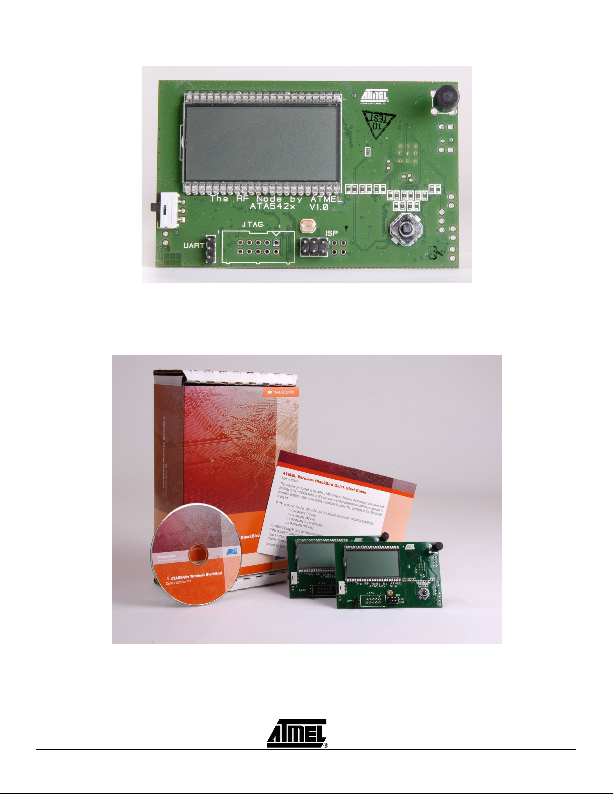
Figure 1-1. Wireless BlackBird Transceiver
Introduction
Figure 1-2. Wireless BlackBird Demonstration Kit
ATAB542x-x-WB User Guide 1-3
5219A–WIRE–04/07

Section 2
Operating the Transceivers
This section contains remarks about how the Menu Guides, both abridged and exhaustive, are set-up and how to use them. Then, both versions of the Menu Guide,
respectively, are given.
2.1 Menu Guide Description
These menu guides are intended to provide the user with two views of the demo-software menu. First, the abridged version shows a top-level view of only the first two tiers
of the menu system. At a glance, the user can see what features are demonstrated in
the pre-loaded software. Second, in the exhaustive version, the user has a simple-tonavigate outline with complete details about each feature in the software. Additionally,
in the exhaustive version, short instructions are given for the demonstrations whose
execution is not intuitively clear from simply the outline material alone.
The following are comments important to understanding these guides and navigating
the Demo software menu:
1. anything that appears on the LCD display is highlighted in the outline with bold
text. This helps the user to more quickly spot the place in this outline that corresponds to the current position in the menu system while using the Wireless
BlackBird.
2. there are 5 possible movement of the joystick:
P - press
L - move left
R - move right
U - move up
D - move down
that result in some action. Each is described in the exhaustive version.
3. where reasonable, a few sentences of explanation either complement or replace
the abbreviated descriptions of the joystick movements.
4. unless otherwise stated, these actions apply to each menu item:
L - backs out of the menu item
P - starts/ends/selects the menu item
So, a very important action that the user MUST remember is:
only by pressing (P) the joystick will a selected menu item be stored in
memory!
ATAB542x-x-WB User Guide 2-1
5219A–WIRE–04/07

Operating the Transceivers
5. the letters "X" or "x" are used in this outline to indicate display of a number that
has a variable value.
2.2 The Abridged Menu Guide
There are 6 main menus:
DIAGNOSTICS
LINK QUALITY
TEMPERATURE SENSOR
LIGHT SENSOR
FREQ HOPPER
SYSTEM SETUP
They are accessible by moving the joystick downward (not to be confused with pressing
it) or upward after power-up. At each main menu which has sub-menus, these submenus can be accessed by pressing the joystick. Moving the joystick leftward backs out
of the currently-selected sub-menu.
These 6 main menus and each one’s sub-menu are described here:
DIAGNOSTICS - provides transmit and receive functions for testing and evaluation.
The sub-menus are:
MARK - transmits a continuous logic "1" (the upper FSK frequency)
SPACE - transmits a continuous logic "0" (the lower FSK frequency)
TOGGLE - generates a continuous square wave by toggling between MARK and
SPACE (FSK mode)
RSSI - indicates received signal strength
PKT TX - transmits packet data
PKT RX - receives packet data
S LINK - serial link mode; permits two PCs to communicate over an RF link
LINK QUALITY - two transceivers exchange data packets with one-another. Each trans-
ceiver displays the relative strength of the signal it receives.
TEMPERATURE SENSOR - two transceivers exchange with one-another the temperature measurement made by each’s on-board sensor. The temperature measured by a
transceiver’s own sensor, as well as that reported by the other transceiver, is displayed.
LIGHT SENSOR - two or more transceivers exchange with one-another the light intensity measurement made by each’s on-board sensor. This is a multi-transceiver
demonstration with a single MASTER and one or more REMOTEs. The intensity measured by a transceiver’s own sensor, as well as that reported by the other transceiver, is
displayed. NOTE: the REMOTEs communicate only with the MASTER – not with other
REMOTEs.
FREQ HOPPER - two transceivers exchange data packets, in either single or continuous mode, as they hop among pre-set channels.
2-2 ATAB542x-x-WB User Guide
5219A–WIRE–04/07

Operating the Transceivers
SYSTEM SETUP - various functions
PWR DWN - puts the transceiver in one of two different sleep modes
CHANNEL ADJUST - adjusts/trims the frequency of the selected channel
UNIT ID ADR - assigns a unit ID to the transceiver
SET DATE/TIME - sets the date and time of the internal clock
PWR LVL - sets the power output (LO ~ 0dBm, HI ~ 8dBm)
LCD SEG ON - displays all segments on the LCD
A/D TST - shows that the A/D converter works
CLK OUT - outputs a square wave at the RC oscillator frequency
TIME - displays day/date/time information
RF MODULE SELECT - loads pre-set register data for each RF frequency
2.3 The Exhaustive Menu Guide
To power-up the transceiver, slide the white-and-black switch downward. The text
ATMEL WIRELESS BLACKBIRD scrolls across the screen. The AVR logo and the
device part number (542x) are also displayed. At this point:
P - displays VERSION X.XX, the current version of the demo software
P,L,R,U,D - goes to power-up display (ATMEL SMARTRF...)
U,D - scrolls through the main menu (DIAGNOSTICS, LINK QUALITY, ...)
P - selects desired menu item
2.3.1 DIAGNOSTICS Contains seven transmit/receive functions
sub-menus: MARK, SPACE, TOGGLE, RSSI, PKT TX, PKT RX, S LINK
P - accesses sub-menus
L - goes to power-up display (ATMEL SMARTRF...)
U,D - scrolls through main menu (DIAGNOSTICS, LINK QUALITY, ...)
2.3.1.1 MARK Transmits a continuous logic "1" (the upper FSK frequency)
P - accesses menu items
L - goes to DIAGNOSTICS
U,D - scrolls thru menu (MARK, SPACE, ...)
CH x - sets radio channel (0 to 9)
P - sets channel and goes to PWR LVL
L - goes to PWR LVL
U - increments channel
D - decrements channel
PWR LVL - sets TX power level
P - sets selected power level (LO/HI) and goes to MARK
L - goes to MARK
U - selects HI power
D - selects LO power
MARK (blinking), channel number, AVR logo, antenna icon, and P LO (or, P HI)
ATAB542x-x-WB User Guide 2-3
5219A–WIRE–04/07
 Loading...