


APPLICATION NOTE
User Guide for the Evaluation Kit A TA8520-EK1-E and the
ATA8520-EK2-E and ATA8520-EK3-E Extension Boards
ATAN0104
Features
● User guide for the evaluation kit ATA8520-EK1-E and extension boards
ATA8520-EK2-E and ATA8520-EK3-E
● This kit demonstrates a Flash application with the
● ATA8520-EK1-E evaluation kit:
with the Atmel
ATmega328P AVR
battery-powered kit for standalone operation
● ATA8520-EK2-E and
Includes Atmel SIGFOX ATA8520D V1.3 transceiver device with an AT30TS75A
temperature monitoring device. An additional MCU application development kit,
i.e. Xplained mini or Arduino UNO is required.
®
SIGFOX™ ATA8520D V1.3 transceiver device and an Atmel
®
microcontroller with AT30TS75A temperature sensor as a
ATA8520-EK3-E extension boards:
Description
This user guide describes an evaluation kit and the extension boards for a SIGFOX
application. This application uses an Atmel ATmega328P AVR microcontroller to
read out an AT30TS75A temperature sensor using the built-in TWI connection and controls
the RF telegram transmission using the SIGFOX ATA8520D V1.3 transceiver device. This
application requires a SIGFOX base station infrastructure to capture the RF telegram and
supply payload data at the SIGFOX back end of the SIGFOX Cloud. For more information
on operating the SIGFOX network and SIGFOX Cloud, see http://www.sigfox.com
information.
The evaluation and development kit tool packs are available for download from the Atmel
website: http://www.atmel.com/devices/ATA8520.aspx. These tool packs include
● The ATAN0054 quick start guide for the kit and the Atmel ATAN0104 user guide
● The schematic, layout and Gerber data for the ATAB0101A PCB
● The source code for the Atmel ATmega328P as an Atmel Studio 6 project
The Atmel ATA8520D SIGFOX transceiver is a SIGFOX-certified device which includes the
complete SIGFOX protocol stack to operate in the SIGFOX network within the 868MHz
ISM band. The device is controlled from any host MCU using the SPI commands as
described in the datasheet [1]. Included in the tool pack is a ATA8520D library as C source
code for the SPI commands.
9373E-AUTO-11/15

References
[1] Atmel® ATA8520D datasheet and user guide
[2] Atmel AT30TS75A datasheet
[3] http://www.sigfox.com
[4] http://backend.sigfox.com
[5] http://www.atmel.com/devices/ATA8520.aspx
[6] Atmel ATAN0054 – ATA8520-EK1-E/EK2-E/EK3-E quick start guide
[7] ATA8520-EK123-E_Tool_pack_V1.0.zip
2
ATAN0104 [APPLICATION NOTE]
9373E–AUTO–11/15
1. Getting Started with the ATA8520-EK1-E Kit
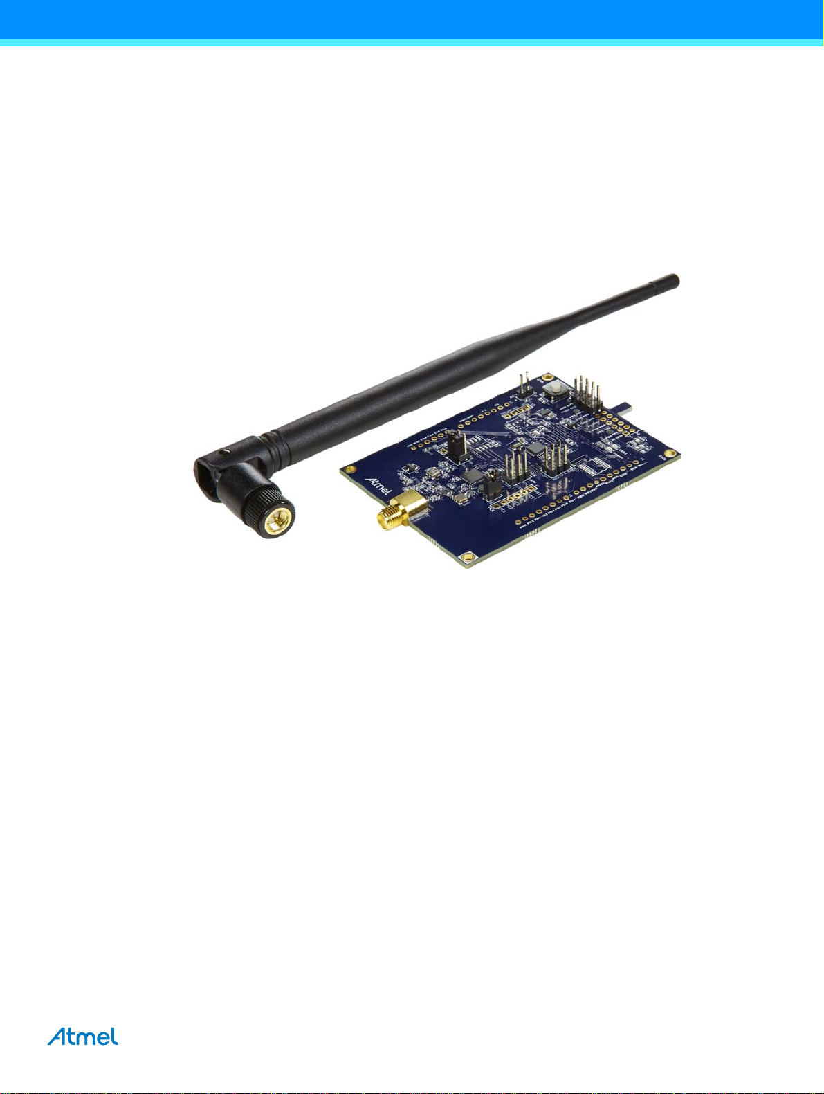
Figure 1-1 shows the components which are included in the evaluation kit. The kit includes
● A single PCB ATAB0101A with
● An Atmel
● An Atmel ATmega328P AVR
● An AT30TS75A temperature sensor with TWI
● An 868MHz monopole antenna for connection to the SMA connector
The kit requires an external power supply or battery for 3.0V to 3.3V at 50mA which is not included in the kit.
Figure 1-1. ATA8520-EK1-E Kit Components
®
ATA8520D SIGFOX™ transceiver device
®
microcontroller at 8MHz
The 868MHz monopole antenna is connected to the SMA connector of the PCB and the external power supply or battery has
to be connected to connector X1.
Caution: Ensure correct polarity at the connection to avoid damage to the equipment. The PCB has no reverse polarity
protection for the power supply connection.
The kit comes with preconfigured devices for starting the Flash application of the Atmel ATmega328P once the power is
applied. This application controls the RF telegram transmission and reads out the temperature sensor at one-hour intervals
or when pressing the SW1 button. The red LED1 starts blinking for about 7-8s, i.e. during telegram transmission. The device
then enters power-down mode until a wake-up from the internal timer or a button press occurs.
Every fifth transmission is executed as an uplink/downlink request, i.e. it will first transmit the RF telegram with sensor data
and requests a payload data packet from the SIGFOX cloud via a base station. The execution of these request will take
about 40-50s.
The Atmel ATA8520D device includes the SIGFOX ID and PAC registration code (see label attached to PCB) to register the
kit with the user's account for the SIGFOX back end. The user has to open a SIGFOX cloud account to access the back end.
From this account the data payload transmitted from the devices can be retrieved in various ways as described in the
SIGFOX online help.
An Atmel debugger (Atmel JTAGICE3 or Atmel ICE), which can be connected to connector XISP1, is required for application
development. Please see the marker for pin1 to connect with the correct orientation. The debugger can only be used if
Atmel Studio 6 is installed in the front end. Atmel Studio 6 can be downloaded from http://www.atmel.com with additional
user instructions and tools. The documentation for the kit components and for the software is included in the tool pack zip
folder [7] which can be downloaded from the Atmel website [5].
The kit and the boards are preprogrammed and temperature calibrated to operate at room temperature (24°C). For operation
with a wider temperature range a temperature calibration as described in “ATAN0142 - ATA8520D Crystal Calibration” has
to be applied. This is mandatory to comply with the CE certification for the kit and boards and is valid for a temperature range
of –20°C to +55°C.
ATAN0104 [APPLICATION NOTE]
9373E–AUTO–11/15
3
2. Getting Started with the ATA8520-EK2-E and -EK3-E Extension Boards
Figure 2-1 and Figure 2-4 show the components which are required for the evaluation kit. The kit includes
● A single PCB ATAB0101A with
● An Atmel
● An AT30TS75A temperature sensor with TWI
● An 868MHz monopole antenna for connection to the SMA connector
The kit is available in two versions depending on the connector type of the additionally required development kit:
● An ATA8520-EK2-E Xplained mini (Figure 2-1): to be used with an additional Xplained mini (Figure 2-2) or Arduino
UNO kit
● An ATA8520-EK3-E Xplained Pro (Figure 2-3): to be used with an additional Xplained Pro kit (Figure 2-4)
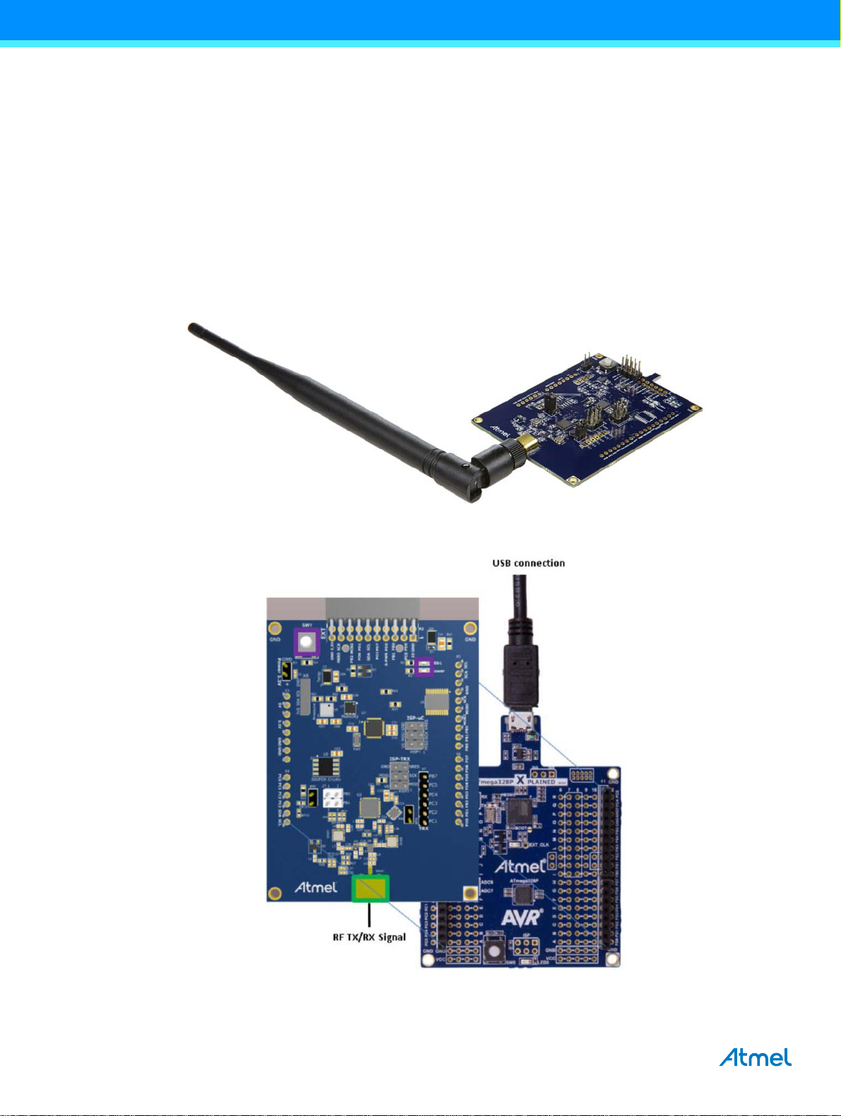
Figure 2-1. ATA8520-EK2-E Xplained Mini Extension Board with Attached External Antenna
®
ATA8520D SIGFOX™ transceiver device
Figure 2-2. ATA8520-EK2-E Xplained Mini Extension Board Mounted on Xplained Mini
4
ATAN0104 [APPLICATION NOTE]
9373E–AUTO–11/15
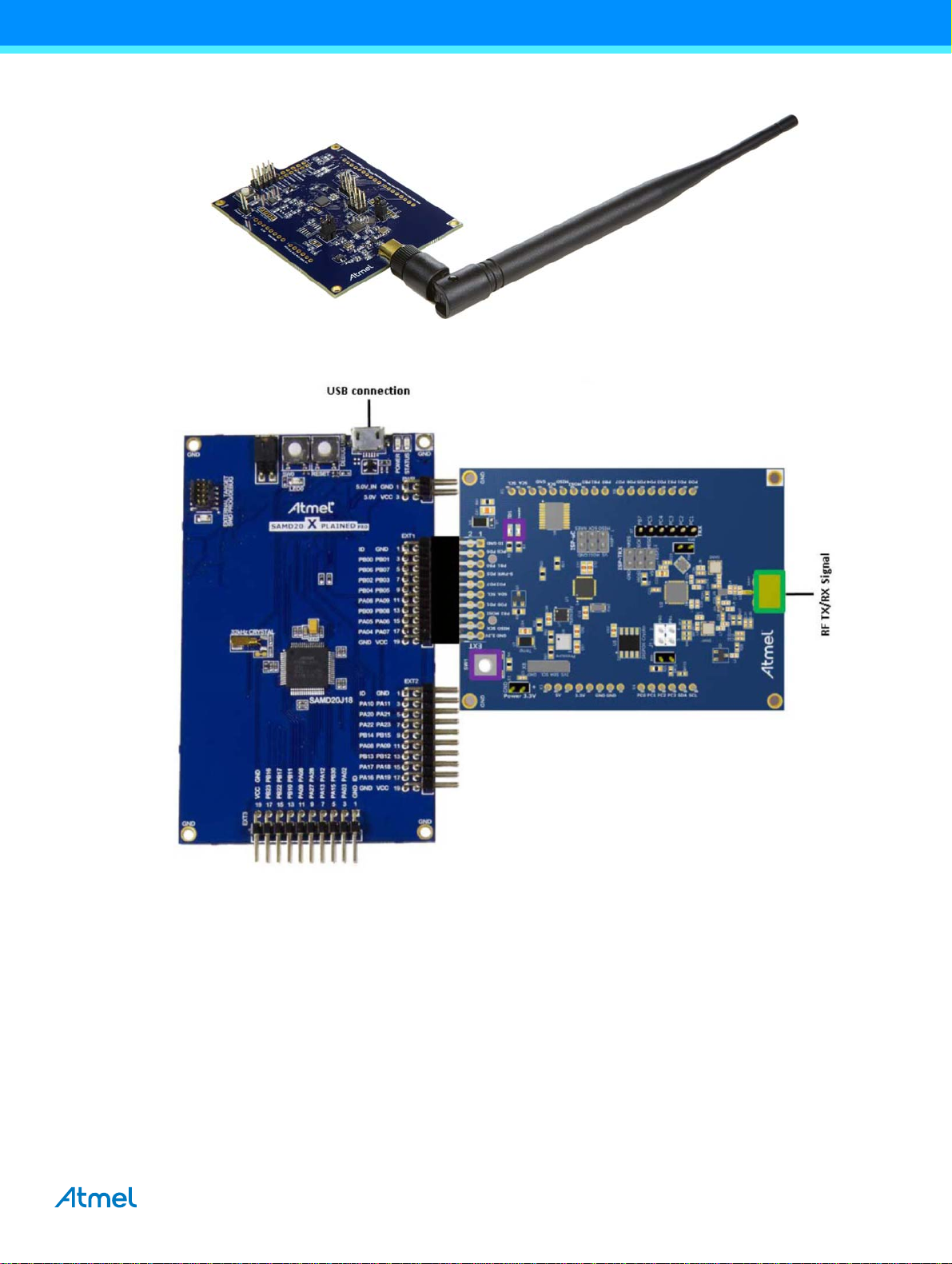
Figure 2-3. ATA8520-EK3-E Xplained Pro Extension Board
Figure 2-4. ATA8520-EK3-E Xplained Pro Extension Board with SAMD21 Xplained Pro Kit
The 868MHz monopole antenna is connected to the SMA connector of the PCB and the board is powered from the attached
evaluation kit using 3V/5V for the ATA8520-EK2-E Xplained Mini and 3V for the ATA8520-EK3-E Xplained Pro.
The following Flash applications are available as part of tool pack distribution:
● Xplained mini – Atmega328P application at 5V/16MHz
● Arduino UNO sketch and library at 5V/16MHz
● SAMD21 application for Xplained Pro at 3V/48MHz
This application controls the RF telegram transmission and reads out the temperature sensor at 15-minute intervals or when
pressing the SW1 button. The red LED1 starts blinking for about 7-8s, i.e. during telegram transmission. The device then
runs in a main loop until an event from the internal timer or a button press occurs.
ATAN0104 [APPLICATION NOTE]
9373E–AUTO–11/15
5

Every fifth transmission is executed as an uplink/downlink request, i.e. it will first transmit the RF telegram with sensor data
and requests a payload data packet from the SIGFOX cloud via a base station. The execution of these request will take
about 40-50s.
The ATA8520D device includes the SIGFOX ID and PAC registration code (see label attached on the PCB) to register the kit
with the user's SIGFOX back-end account. The user has to open a SIGFOX cloud account to access the back end. From this
account the data payload transmitted from the devices can be retrieved in various ways as described in the SIGFOX online
help.
The Atmel debugger included in the development kits can be used for application development. Application development
and use of the debugger is only possible if Atmel Studio 6 is installed in the front end. Atmel Studio 6 can be downloaded
from http://www.atmel.com with additional user instructions and tools. The documentation for the kit components and for the
software is included in the tool pack zip folder [7] which can be downloaded from
http://www.atmel.com/devices/ATA8520.aspx.
6
ATAN0104 [APPLICATION NOTE]
9373E–AUTO–11/15
 Loading...