

Atmel ATA8510-EK1 Application Note

ATAN0046
User Guide for the Evaluation Kit ATA8510-EK1
APPLICATION NOTE
Features
• User guide for the ATA8510-EK1 evaluation kit
• Demonstrates an application with the
– RF transceiver Atmel® ATA8515 in a base station with an
Xplained PRO SAMD20 kit
– Atmel ATA8510 RF transceiver remote sensor with an
AT30TS75A temperature sensor and an optional CMM-1923
real-time clock
– Two-way RF communication
• New software version of the SAMD20 base station V2.0 is without
FreeRTOS
Description
This user guide describes an evaluation kit for industrial RF applications
having the following components:
• A base station using an
– Xplained PRO SAMD20 evaluation kit
– Xplained PRO OLED1 extension board
– Xplained PRO ATA8510/15 extension board
• Remote temperature sensor with Atmel® ATA8510 running a Flash
application
The Atmel ATA8515 is used as an RF transceiver in the base station and
runs in polling mode to detect data telegrams and displays the received
message on the OLED. The received message is also streamed to a PC
terminal program using a virtual COM port connection.
The remote sensor includes an AT30TS75A temperature sensor device and
a CMM-1923 real-time-clock device for waking up the Atmel ATA8515 RF
transceiver. The Flash application reads the temperature data from the
sensor device using a TWI bus protocol implemented in software and
broadcasts the temperature data via the RF link.
The RF application uses a 2-way communication, i.e., the transmitted RF
telegrams are acknowledged from the receiver.
Atmel-9343D-ATAN0046_Application Note-09/2016

The RF link operates on channel 433.92MHz at an 8kBit/s data rate using FSK modulation with
Manchester encoding.
References
[1] Atmel® ATA8510/ATA8515 datasheet
[2] Atmel AT30TS75A datasheet
[3] C-MAX CMM-1923-V1.0 datasheet
[4] http://www.atmel.com
[5] http://www.iar.com
[6] Atmel ATAN0096 - ATA8510 Programmers Guide
[7] Atmel ATAN0035 - ATA583x and ATA578x Configuration Tool Guide and software
[8] Atmel ATAN0036 - ATA583x and ATA578x Flash Application Development
[9] Atmel ATA8510/ATA8515 User Manual
[10] ATA8510-EK1_Tool_Pack_V2.0.zip
Atmel User Guide for the Evaluation Kit ATA8510-EK1 [APPLICATION NOTE]
Atmel-9343D-ATAN0046_Application Note-09/2016
2

Table of Contents
Features.......................................................................................................................... 1
Description.......................................................................................................................1
References...................................................................................................................... 2
1. Getting Started...........................................................................................................4
1.1. Kit Setup.......................................................................................................................................4
1.2. Upgrade Kit V1.x to V2.0 .............................................................................................................6
2. Data Protocol and Signal Timing............................................................................... 7
2.1. Data Protocol for Remote Sensor Telegram.................................................................................7
2.2. Data Protocol for Base Station Acknowledge...............................................................................8
2.3. Signal Timing................................................................................................................................8
3. Hardware Description................................................................................................ 9
3.1. Base Station Transceiver............................................................................................................. 9
3.2. Remote Sensor Transceiver.......................................................................................................10
4. Software Description................................................................................................13
4.1. Flash Application for the ATA8510 Remote Sensor................................................................... 13
4.2. Base Station Application for SAMD20 MCU...............................................................................14
4.3. Software Development...............................................................................................................16
4.4. EEPROM Data Settings............................................................................................................. 20
5. Revision History.......................................................................................................21
1. Getting Started
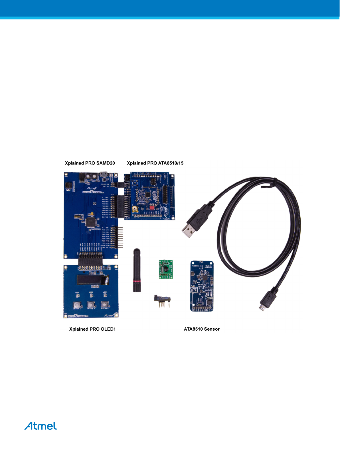
Figure 1-1 shows the components which are included in the evaluation kit. The kit includes
• A base station with
• Xplained PRO SAMD20 evaluation board
• Xplained PRO OLED1 extension board
• Xplained PRO ATA8510/15 extension board
• A remote temperature sensor with Atmel® ATA8510 [1], AT30TS75A [2], and an optional CMM-1923
[3] devices
• A mini USB cable
• A mini ISP adapter
• A 433MHz whip antenna
The remote sensor requires a CR2032 coin cell battery not included in the kit.
Figure 1-1. ATA8510-EK1 Kit Components
1.1. Kit Setup
The Xplained PRO OLED1 board is connected to the EXT3 extension header and the Xplained PRO
ATA8510/15 board is connected to the EXT1 extension header of the Xplained PRO SAMD20 board as
shown in Figure 1-2. The 433MHz whip antenna is mounted on the X4 connector of the Xplained PRO
ATA8510/15 board. These boards are powered using the USB cable connected to the debug USB
connector of the Xplained PRO SAMD20 board. The USB cable can be connected to a 5V/500mA USB
power supply for stand-alone operation. When using the virtual COM port, the USB cable is connected to
Atmel User Guide for the Evaluation Kit ATA8510-EK1 [APPLICATION NOTE]
Atmel-9343D-ATAN0046_Application Note-09/2016
4
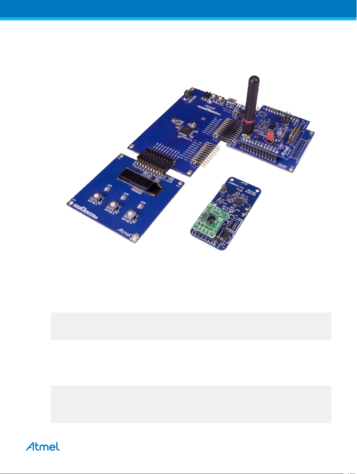
a PC's USB port, which requires previous installation of Atmel Studio 6 or 7 IDE [4]. This installation
includes all required USB drivers for operation of the Xplained PRO SAMD20 board.
Figure 1-2. ATA8510-EK1 Kit
Atmel Studio 6 or 7 can be downloaded from [4] with additional user instructions and tools.
Documentation for the Xplained PRO SAMD20 and Xplained PRO OLED1 are also available from [4].
Documentation for other components in the kit and the software is included in the tool pack zip folder [10]
available on the Atmel web site [4].
The OLED displays a welcome screen after power-up
ATA8510-EK1 Demo Kit
(c)2016 Atmel V2.0
ATA8515 V1.2
wait for RF signal ...
and waits for an RF telegram from the remote sensor. After installing the CR2032 coin cell into the remote
sensor (be sure to observe correct polarity), the sensor immediately starts sending RF telegrams at 2s
intervals when the optional RTC module is installed. The OLED shows the temperature value from the
sensor with a resolution of 1°C. The time interval between the RF signal reception in seconds and the
signal strength rssi on the base station and RSSI on the sensor is also shown:
___________________
| dt=2s rssi=221 |
| |
| T=22°C |
| RSSI=128 |
|___________________|
Atmel User Guide for the Evaluation Kit ATA8510-EK1 [APPLICATION NOTE]
Atmel-9343D-ATAN0046_Application Note-09/2016
5

When removing the CMM-1923 real-time clock, the transmission of an RF telegram can be initiated by
pressing the S2 button (for more information, see Figure 3-2). The display can be switched to different
modes via the buttons 1-3 on the Xplained PRO OLED1 extension board (for more information, see
section Base Station Application for SAMD20 MCU).
The tool pack zip folder [10] contains the documentation and software for the kit. Extract the folder into a
directory on the PC to get the following structure:
..\Application_Notes Documentation for the kit and the application notes
for the devices
..\Documentation Device datasheets
..\Hardware Hardware documentation of the boards
..\Software Kit software and tool support extensions
..\Software\Programming_Files Device programming files in *.hex format
..\Software\IDE_Support_Files Tool support files for IAR Workbench and Atmel
Studio 6
..\Software\base Software project and sources for the Xplained PRO
kit
..\Software\base\EEPROM Configuration file for the Atmel ATA8515 device of
the base station
..\Software\base\SAMD20_XplainedPRO_SW Atmel Studio 6 or 7 project directory
..\Software\sensor Software project and sources for the remote sensor
..\Software\sensor\EEPROM Configuration file for the Atmel ATA8510 device of
..\Software\sensor\ATA5831_FLASH_IAR_2.32.0 IAR Embedded Workbench project directory
1.2. Upgrade Kit V1.x to V2.0
Any Atmel® ATA8510-EK1 kit can operate with V2.0 tool pack by programming the SAMD20 base station
with the application software from tool pack V2.0 [10]. The remote sensor need no update and will
operate with V1.x and V2.0 base station applications (see section Xplained PRO SAMD20 Base Station
for more details).
the remote
sensor
Atmel User Guide for the Evaluation Kit ATA8510-EK1 [APPLICATION NOTE]
Atmel-9343D-ATAN0046_Application Note-09/2016
6

2. Data Protocol and Signal Timing
The remote sensor is sending a RF data telegram every 2s or when the button S2 is pressed with the
temperature data. The base station receiver is polling for this data telegram on RF channel 433.92MHz in
regular intervals of 5ms. The RF transmission and data protocol of the remote sensor and the base
station is using the following settings:
• Transmission order is MSB first for preamble and data section
• RF channel: 433.92MHz
• Data rate: 8kBit/s with FSK modulation and Manchester encoding
• Deviation: ±8kHz
Each data packet uses 2 bits before and after the data telegram to force a Manchester code violation,
which is detected by the receiver to separate the data packets and to restart the synchronization
procedure of the receiver.
2.1. Data Protocol for Remote Sensor Telegram
The remote sensor data protocol parameters are shown in Table 2-1. The Manchester encoding is using a
low-to-high transition for a '0' bit and a high-to-low transition for a '1' bit.
Table 2-1. Data Protocol
Protocol Item
Preamble 55 ‘1’ Pre-burst for wake-up and synchronization
Start bit 1 ‘0’ Start bit to indicate data payload
Data payload
Total 88 Data telegram with Ttx = 11ms at 8kBit/s
# of Data Bits Value Description
0x14 ID for no valid sensor data
8
16 Signed integer Temperature value (0.1°C resolution)
8 Checksum Checksum of ID and data payload as 2th complement
0x19 ID for low battery voltage (VCC < 2.2V)
0x64 ID for temperature data (–55 to +125°C)
The acknowledge protocol send by the remote sensor has the following data:
Table 2-2. Acknowledge Protocol
Protocol Item
Preamble 55 ‘1’ Pre-burst for wake-up and synchronization
Start bit 1 ‘0’ Start bit to indicate data payload
Data payload
Total 88 Data telegram with Ttx = 11ms at 8kBit/s
# of Data Bits Value Description
8 0x60 ID for RSSI data
16 Integer RSSI value [0-255]
8 Checksum Checksum of ID and data payload as 2th complement
Atmel User Guide for the Evaluation Kit ATA8510-EK1 [APPLICATION NOTE]
Atmel-9343D-ATAN0046_Application Note-09/2016
7
 Loading...