

Page 1
Atmel ATAN0007
User Guide for ATA5830N 2-way 3-channel Demo
Features
• Complete Bi-directional RF System Reference Design Based on the Atmel ATA5830N
Transceiver that uses a Multi-channel Protocol for Robust Operation
• Included in the Kit are:
– Handheld Key Fob Reference Design using PCB Loop Trace Antenna
– Vehicle Side Reference Design using Monopole Whip Antenna
– Interface Board for STK600 Connectivity (STK600 not Included)
Reference Documents
• ATA5830N.pdf
• Sigma_STK600EEPROM_Setting_RXTX_demo.xls
• testEEPROM_Setting_RXTX_default.xls
1. Overview
The Atmel® ATA5830N is highly integrated UHF ASK/FSK transceiver with low power
consumption available in a small 5x5mm
developed as a fully integrated low IF double quadrature receiver with an embedded
®
AVR
microcontroller including the transmit functionality with a closed loop frac-
tional-N modulator with Gauss-shaping and pre-emphasis for high data rates.
2
QFN32 package with 0.5mm pitch. It is
Atmel
ATAN0007
Application Note
The Atmel ATA5830N can be setup for the following frequency bands:
• 310MHZ to 318MHz
• 418MHZ to 477MHz
• 836MHz to 928MHz
The transceiver combines the functionality of Remote Keyless Entry (RKE) and Tire
Pressure Monitoring (TPM) applications in one chip under the control of an embedded
AVR microcontroller. The flexibility of this device allows the programming of a wide
range of RKE applications, like Passive Entry Go (PEG) and Remote Start (RS)
together with the TPM applications.
The Atmel ATAK51002 evaluation kit provides a complete reference design for a
bi-directional RF system based upon the Atmel ATA5830N. It provides standalone
operation of two Atmel ATA5830N transceivers, one hand-held key fob and one connected to the Vehicle Host Controller. Unencrypted data is exchanged between the
two transceivers and is output via an RS232 connection to a PC. The raw data can be
viewed with a hyper-terminal application. The kit setup and configuration are
described in the following sections. Further information is available in the reference
documentation.
9252A–RKE–10/11
Page 2

2. Getting Started
2.1 Kit Contents
This kit contains the following items:
• CAR System Interface Board
• Atmel ATA5830N Transceiver Board
• Atmel ATA5830N handheld key fob
• Monopole whip antenna
• RS232 serial cable
• Digitus USB to Serial interface converter
• 120/240AC to 12VDC wall transformer
• (3) 10-wire cables for I/O port connections between STK600 and System Interface Board
• Atmel CD-ROM with datasheets, reference designs, and software
Note: A Atmel STK600 is required, but not included in this kit. Please contact www.atmel.com or you
local Atmel Sales office for more info on obtaining one.
Figure 2-1. Atmel ATAK51002 Application Kit
2
Atmel ATAN0007
9252A–RKE–10/11
Page 3
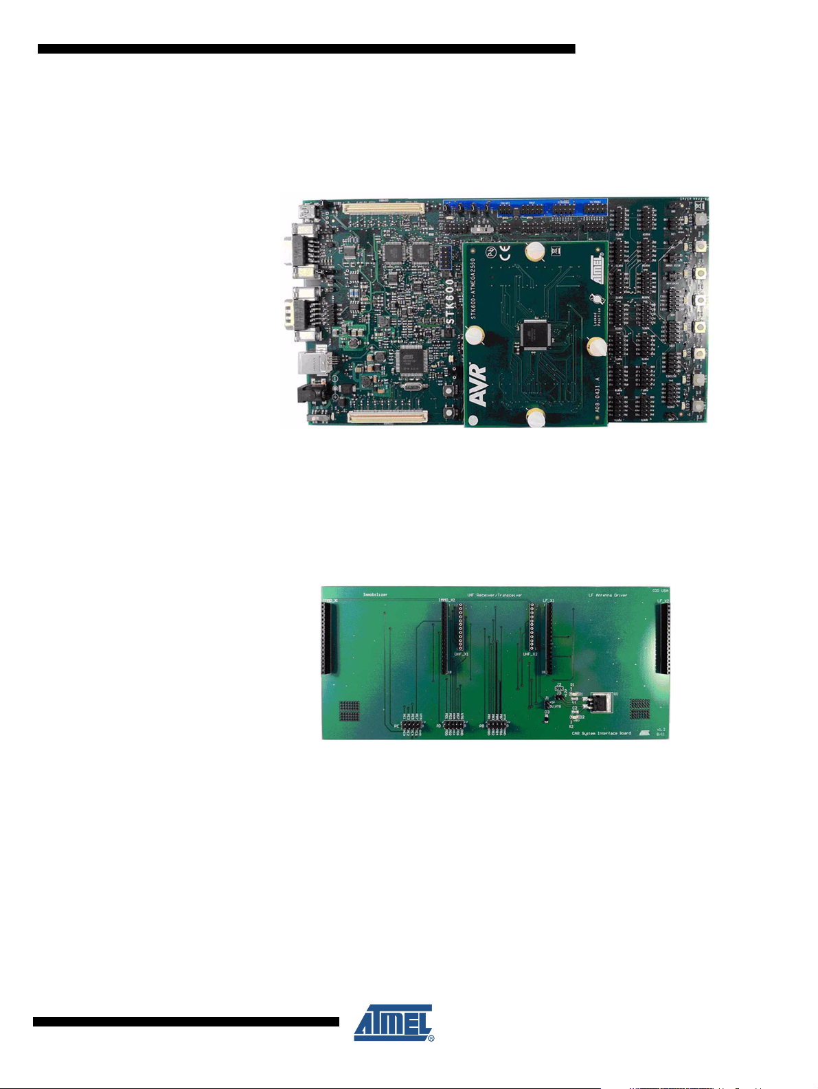
2.1.1 Atmel STK600
Atmel ATAN0007
The Atmel
tions as the Vehicle Host Controller for the Atmel ATAK51002 application evaluation kit.
Figure 2-2. Atmel STK600 Host Controller Module
®
STK600 along with the Atmel ATmega2560 microcontroller expansion board func-
2.1.2 CARS Interface Board
The CARS (Car Access Reference System) Interface Board is the gateway between the Atmel
STK600 Vehicle Host Controller and the Atmel ATA5830N Transceiver Board. Additional interface headers are included for future kit expansion to include immobilizer and passive entry
functionality.
Figure 2-3. CARS Interface Board
9252A–RKE–10/11
3
Page 4
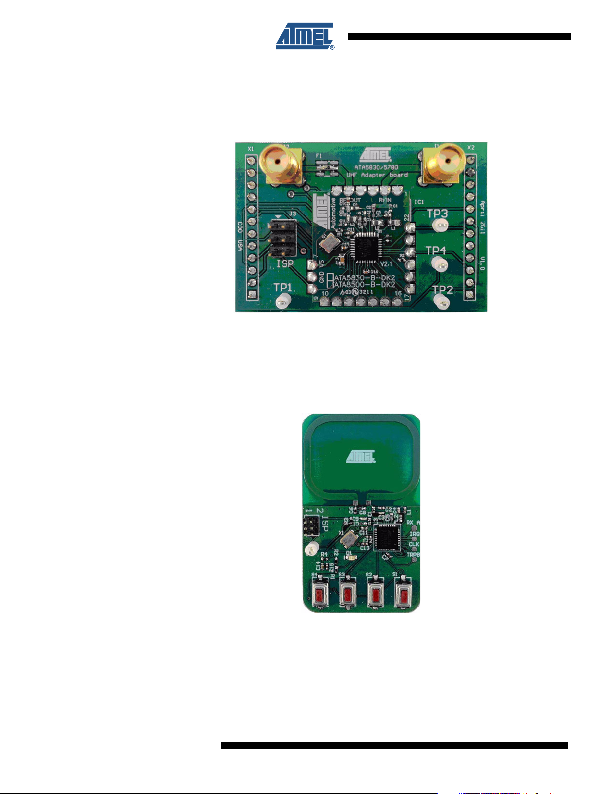
2.1.3 Atmel ATA5830N Transceiver Board
The Atmel
hand-held key fob and the Atmel STK600 Vehicle Host Controller.
Figure 2-4. Atmel ATA5830N Transceiver Board
2.1.4 Atmel ATA5830N Key Fob
The Atmel ATA5830N key fob is a hand-held transceiver used to communicate with the Atmel
STK600 Vehicle Host Controller. The key fob contains four buttons, each capable of transmitting unique data over the RF link to the Host Controller.
®
ATA5830N Transceiver Board provides the RF link between the Atmel ATA5830N
Figure 2-5. Atmel ATA5830N Transceiver Key Fob
4
Atmel ATAN0007
9252A–RKE–10/11
Page 5
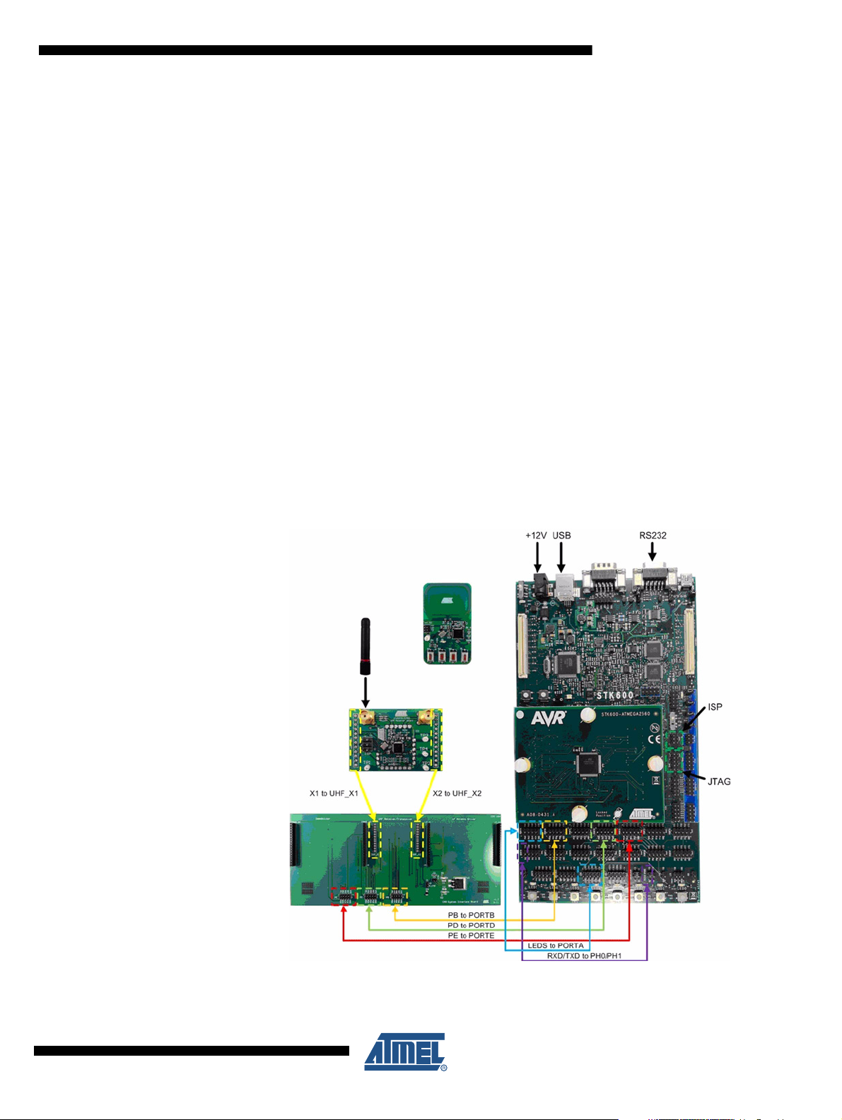
2.2 Connecting the Hardware
Prepare the Atmel® STK600 with the Atmel ATmega2560 device board as described in the
Atmel STK600 User Guide. Using a 2-wire cable supplied with the Atmel STK600, connect
RS232 SPARE pins RXD and TXD to PORTH pins PH0 and PH1 making sure RXD connects
to PH0 and TXD connects to PH1. Using the two 10-wire cables supplied with the Atmel
STK600, connect PORTA to LEDS. Using the three 10-wire ribbon cables supplied with the
CARS evaluation kit, make connections from the Atmel STK600 to the System Interface
Boards; PORTB to PB, PORTD to PD, and PORTE to PE.
Note: Be sure to properly match header alignment to pin 1 on both ends of the cable when making
these connections.
Mount the Atmel ATA5830N Transceiver Application Board to the System Interface Board taking care to align the X1 and X2 pin headers on the Transceiver Application Board to the
UHF_ X1 and UHF_X2 pin sockets on the System Interface Board. Connect monopole RF
whip antenna to the Transceiver Application Board and ensure that a jumper is installed onto
J1.
Complete the set-up by connecting supplemental 12VDC power from the wall transformer to
the mating receptacle on the Atmel STK600 and connect the USB and RS232 ports to the PC
with the supplied cables. Also install a CR2032 Li-ion coin cell battery (not included with the kit
due to governmental shipping regulations) into the hand-held key fob. Please ensure that the
“+” side of the battery is correctly aligned with the “+” on the metal battery clip on the key fob.
Atmel ATAN0007
Figure 2-6. Atmel ATAK51002 Hardware Interconnection
9252A–RKE–10/11
Note: Use the USB to Serial converter dongle included with the kit if your PC does not have an RS232
port.
5
Page 6
2.3 Device Programming
2.3.1 Atmel ATmega2560 Host Controller
Since the Atmel
ATmega2560 Host Controller must be flashed with the Atmel ATA5830N application firmware
to operate. In-System Programming of the Atmel ATmega2560 can be done using the AVR
internal SPI (Serial Peripheral Interface) to download code into the flash and EEPROM memory. ISP programming requires only VCC, GND, RESET and 3 signal lines for programming.
No high voltage signals are required. The ISP programmer can program both the internal flash
and EEPROM, fuses, lock bits and calibration bytes. The ISP frequency (SCK) must be less
than 1/4 of the target clock. The ISP frequency is set by the Atmel STK600 programming dialog in AVR Studio. Refer to the Atmel STK600 User Guide for additional information.
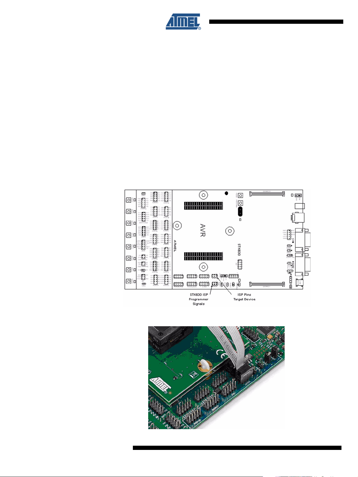
To program the Atmel ATmega2560 on the device card installed in the Atmel STK600, connect a 6-wire cable between the two 6-pins ISP headers on the Atmel STK600. See Figure 2-7
and Figure 2-8 below. Ensure that the VTARGET jumper is mounted, and that the voltage is
the within the operating range for the target device.
Figure 2-7. Atmel STK600 ISP Headers
®
STK600 hardware is not included with the Atmel ATAK51002 kit, the Atmel
®
Figure 2-8. ISP 6-Wire Ribbon Cable Connection
6
Atmel ATAN0007
9252A–RKE–10/11
Page 7
Atmel ATAN0007
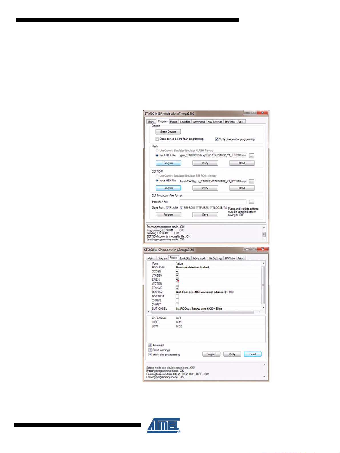
Using AVR Studio®4, program the Atmel® ATmega2560 on the Atmel STK600 by selecting
Tools/AVR Programming to bring up the ISP menus. Select and specify the Tool, Device,
Interface, and Target Voltage as shown below and browse to locate files titled
“ATAK51002_V1_STK600.hex” and “ATAK51002_V1_STK600.eep”. The files can be found in
the CD-ROM supplied with the CARS kit. Be sure to set the target voltage for 5.0V when programming the Atmel ATmega2560. Refer to Figure 2-9 for a screen shot of the properly
completed ISP programming menu along with a view of proper fuse settings.
Figure 2-9. ISP Programming and Fuse Menus for the Atmel ATmega2560
9252A–RKE–10/11
7
Page 8
2.3.2 Atmel® ATA5830N Transceiver Board
Standalone programming of the Atmel
Atmel ATA5830N Transceiver Board is automatically configured whenever power is first
applied to the Vehicle Host Controller.
®
ATA5830N Transceiver Board is not required. The
2.3.3 Atmel ATA5830N Key Fob
AVR Studio
gram the Atmel ATA5830N hand-held key fob. Run the “ATA5830include2AVRstudio.exe”
executable file included on the CD-ROM with the Atmel ATAK510020 kit. Once the installation
has completed, start AVR Studio4, install a CR2032 battery into the key fob (not included with
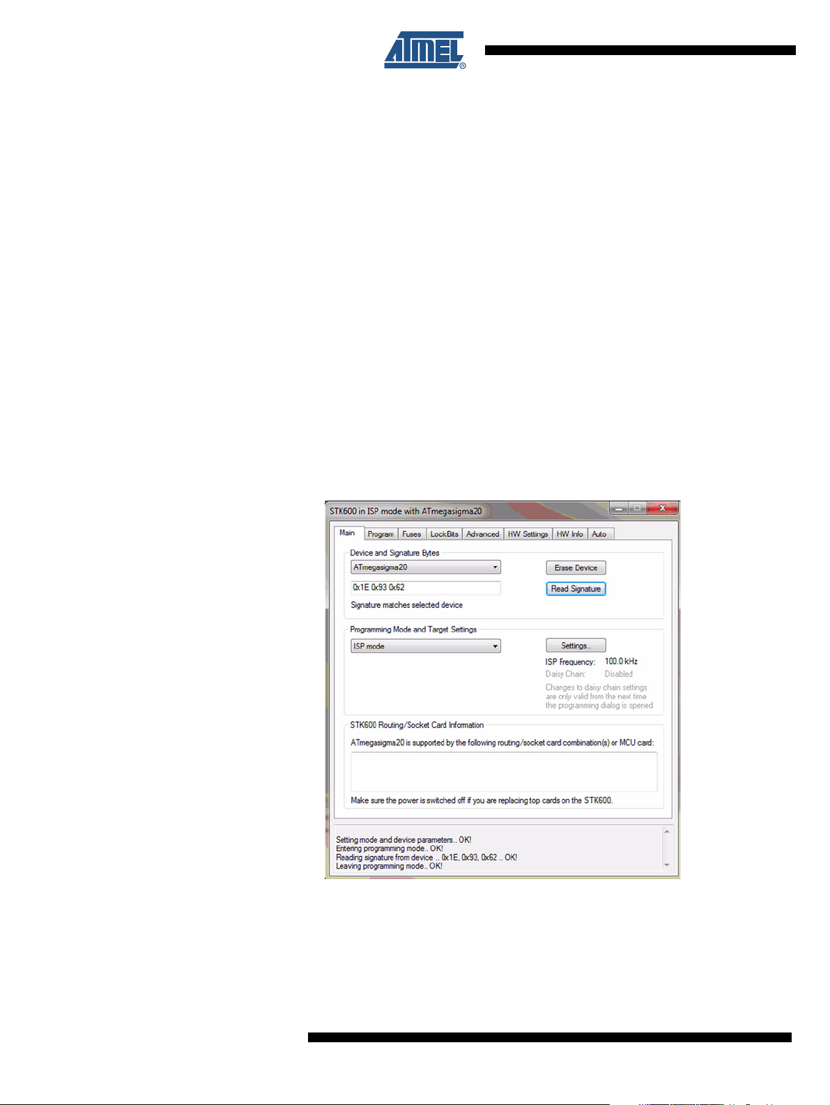
the kit) and connect the included 6-wire ISP cable between the Atmel STK600 ISP programming header and the ISP header on the Atmel ATA5830N key fob. Connect to the key fob
through the AVR Studio4 using the Atmel STK600 and configure the device from the “Main”
menu tab for programming with the Device set to “ATmegasigma20”, Programming Mode set
to “ISP Mode” and the ISP frequency to 125kHz (the device may not program at higher frequencies). Figure 2-10 is a screen capture of the correct device setting.
Note: In order to read the device Signature Byte, read/program the fuse settings or program the
Figure 2-10. Atmel ATA5830N AVR Studio4 Main Menu Configuration
®
4 must be updated with the Atmel ATA5830N hardware profile in order to pro-
flash/EEPROM, the Atmel ATA5830N must be operating in the Idle Mode (default state is Sleep
Mode). To wake the device up from Sleep, PRESS and HOLD any key fob button for the duration of the read, write or programming operations.
®
Next, program the Atmel
ATA5830N fuses settings using the “Fuse” menu tab. Ensure that
the SPIEN and EESAVE fuses are set with all others unchecked, see Figure 2-11 on page 9.
8
Atmel ATAN0007
9252A–RKE–10/11
Page 9

Atmel ATAN0007
Figure 2-11. Atmel ATA5830N AVR Studio®4 Fuse Configuration
Finally, program the flash with the file “ATAK51002_V1_FOB.hex” and EEPROM with
“ATAK51002_V1_FOB.eep”.
Figure 2-12. Atmel ATA5830N AVR Studio4 Program Configuration
2.4 Hyper-terminal Application
Download and install a Hyper-terminal application for communication between the PC and the
Atmel STK600 Vehicle Host Controller using the RS232 interface. Any Hyper-terminal application like HyperTerminal, HTerm or RealTerm are suitable for use with the Atmel ATAK51002
evaluation kit.
9252A–RKE–10/11
9
Page 10

3. Running the Demo Application
With the application boards connected, the hardware programmed and the Atmel® STK600
powered and connected to the PC via the USB and RS232 ports, it is now time to run the
demo. Begin by running the Hyper-terminal application on the PC and configure it as follows:
The Hyper-terminal application must be configured as follows:
• Port: will vary depending on your PC configuration
• Baud: 38.4kbaud
• Data Bits: 8
• Stop Bits: 1
• Parity: None
• HW Handshake: None
• Newline at: CR
Communication between the key fob and the Vehicle Host Controller utilizes a bi-directional
protocol where a message is transmitted by the key fob when a button is pressed. The Host
Controller then responds to the transmission from the key fob in the form of an ACK (acknowledge). The key fob application is configured as a Flash application for the Atmel ATA5830N
using the internal ROM firmware and controls the four key switches and the LED located on
the key fob. The Vehicle Host Controller application uses the Atmel STK600 with the on-board
Atmel ATmega2560 expansion board to control the operation of the Atmel ATA5830N via the
SPI commands as described in the Atmel ATA5830N datasheet.
A button press on the key fob transmits 9 bytes of data to the Host Controller. This data along
with the incoming received data channel number, RSSI level and button number are output via
the RS232 link to the PC. The data can then be viewed using the Hyper-terminal application.
Figure 3-1. Hyper-terminal Key Fob Data Output
10
Atmel ATAN0007
9252A–RKE–10/11
Page 11

Atmel ATAN0007
Additionally, the button number and incoming received data channel can be viewed on the
®
Atmel
ton #1 is LED0. The incoming channel number is read from right to left as well on LEDs 4-7
where channel #1 is LED4. With each incoming data transmission from the key fob, the LEDs
will be updated. The LEDs will remain illuminated for approximately 2 seconds before returning to the default “off” state.
Figure 3-2. Atmel STK600 Status LEDs
STK600 output LEDs. The button number is read right to left on LEDs 0-3 where but-
9252A–RKE–10/11
11
Page 12

4. Atmel ATA5830N Data Telegram Overview
4.1 Transmission Protocol
This demo uses a bi-directional communication protocol with a message part and an acknowledge part (ACK). Figure 4-1 shows the data transmission using three different RF channels
indicated by three different colors. In the following sections, scenarios with and without
acknowledge are described, and the data protocol details are explained.
Figure 4-1. Data Transmission with Three Different Channels
Channel 1 Channel 2 Channel 3
4.1.1 Transmission without ACK Message
The first scenario considers that no base station is in the receiving range of the key fob. The
data transmission shown in Figure 4-2 starts with the transmission of a 32 byte data messages
on the three RF channels. After this transmission the key fob switches into the Polling Mode to
be able to receive an ACK message. In Polling Mode the key fob is switched between the RX
Mode and the IDLE Mode or OFF Mode used for power saving. When a time period of 500ms
expires the Polling Mode will be stopped and the key fob is set into the OFF Mode. During the
data transmission the LED of the key fob is switched on.
Figure 4-2. Data Transmission without Base Station Reply
Event:
Switch pressed
TX Key
Fob
2 byte
3
LED on
RX Key
Fob
500ms
15ms
12
Atmel ATAN0007
9252A–RKE–10/11
Page 13

4.1.2 Transmission with ACK Message
32 byte
500ms
26 byte
Depence on channel
15ms
LED on LED on
TX Key
Fob
Event:
Switch pressed
Data valid?
Indicate by LED
RX Key
Fob
RX Car
TX Car
In this scenario the base station is in the receiving range of the key fob with a data transmission shown in Figure 4-3. The key fob is sending the data telegrams on the three channels, as
described before, while the base station is in Polling Mode. The base station is receiving the
first data telegram while the key fob is switched into the Polling Mode after the data transmission on all channels. The base station is analyzing the received data payload and in case that
the message is correct an ACK message is send out on the RF channel which was used for
the message reception. It is important that the key fob is in Polling Mode when the base station starts to send out the ACK message. This is achieved inside the base station by adapting
the delay for sending the ACK message according to the channel. After receiving the ACK
message the data is verified and in case that the ACK was correct, the LED of the key fob is
switched on for another 500ms to indicate a successful communication. Now the key fob will
be set into OFF Mode and the base station is set into Polling Mode again. If the data from the
ACK message could not be verified the key fob is immediately switched into the OFF Mode.
Figure 4-3. Data Transmission with Base Station Reply
Atmel ATAN0007
9252A–RKE–10/11
13
Page 14

4.2 Data Telegram
This section describes the data telegram of the message part which is sent out by the key fob.
The data telegram consists of 32 bytes as follows:
Preamble
[183 bit]
The data direction of the bytes is LSB first for every byte.
4.2.1 Data Synchronization
The data synchronization is achieved during the transmission of the preamble and is followed
by a start bit.
4.2.1.1 Preamble Data
The preamble data is a stream of identical data bits that is used to synchronize the receiver
with the transmitted data stream. To reduce the power consumption the receiver is switched
on for short time periods to check for a data stream and is switched in Sleep or Power-down
Mode when no data is available (Polling Mode). The time periods for the activation must
ensure that the data reception is possible at all times which is achieved when the preamble is
covering two active phases. The following preamble is used for this demo:
4.2.1.2 Start Bit
The start bit indicates the end of the preamble and the end of the synchronization period. In
addition it indicates the start of the payload data. To ensure that the start bit is detectable by
the receiver it must be a bit with the inverted polarity of the preamble data. Thus the demo will
use the following start bit:
Start Bit
[1 bit]
Preamble
bit [182…0] = 0000…0000
Pattern ID
[32 bit]
Telegram Number
[16 bit]
Data
[8 bit]
CRC
[16 bit]
4.2.2 Payload Data
4.2.2.1 Pattern ID
14
Atmel ATAN0007
Start Bit
bit [0] = 1
The payload data is following the synchronization period of the telegram. This part includes a
pattern ID, a telegram number, additional data and a CRC checksum.
To avoid the reception of invalid and unwanted data the ID scan function is used in the demo.
The definition of the IDs is part of the EEPROM configuration data and the demo setup uses
the following ID:
ID Pattern
bit [31…0] = 0x51, 0x4E, 0x87, 0xA9
9252A–RKE–10/11
Page 15

4.2.2.2 Telegram Number
The 16-bit telegram number will be incremented with every transmitted telegram packet and is
defined as follows:
In this demo the number will be 1 for every key event.
4.2.2.3 Data (Key Information)
The data part is one byte long and defines the number of the pressed key as follows:
Atmel ATAN0007
Telegram Number
bit [15…0] = 1
Data (Key Information)
bit [7...0] = 0x01 for switch 1
0x02 for switch 2
0x04 for switch 3
0x08 for switch 4
4.2.2.4 CRC
The CRC checksum is used for the verification of the correct transmission of the telegram. The
receiver can check the data payload with the polynomial x^8+x^2+x^1+1. For the generation
of the CRC a hardware block inside the ATA5830 is used. The payload data is copied to the
data input register of the CRC block and returns a two byte checksum. This hardware block
performs only 8 bit CRC calculations so that the high byte of the CRC checksum is always
0xFF. The CRC part of the payload is defined as follows:
CRC
bit [15…0] = 0xFF, <CRC from register CRCDRO>
The used CRC polynomial is x^8+x^2+x^1+1
9252A–RKE–10/11
15
Page 16

4.3 ACK Telegram
The acknowledge telegram confirms that a correct message was received by the base station
and is sent out by the base station.
The ACK telegram includes 26 byte with the following format:
Preamble
[183 bit]
Start Bit
[1 bit]
The data direction of the ACK message is LSB first for every byte.
4.3.1 Data Synchronization
The data synchronization is achieved during the transmission of the preamble followed by a
start bit as described in Section 4.2 “Data Telegram” on page 14 for the data telegram.
4.3.2 Payload Data
The payload data is following the synchronization part of the telegram. This part includes a
data byte and a CRC checksum.
4.3.2.1 Data (Key and Channel Information)
The data is used to indicate to the key fob, that the received message was correct and
includes the key number of the pressed key and the RF channel number, which was used for
the reception in the base station. The MSB of the data byte is used as an ACK bit. The data
byte format is as follows:
Data (ACK, Key and Channel Information)
data bits[3...0] = 0x1 for switch 1
0x2 for switch 2
0x4 for switch 3
0x8 for switch 4
data bits[5...4] = 0x1 for channel 1
0x2 for channel 2
0x3 for channel 3
data bit[7] = 0x1 for ACK
Data
[8 bit]
CRC
[16 bit]
4.3.2.2 CRC
16
Atmel ATAN0007
The CRC checksum is used for the verification of the correct transmission of the telegram as
described in Section 4.1 “Transmission Protocol” on page 12 for the data telegram.
9252A–RKE–10/11
Page 17

4.4 Data Transmission Timing
31 byte
500ms
26 byte
Depence on channel
15ms
27ms
35ms
65ms
LED on LED on
TX Key
Fob
Event:
Switch pressed
Data valid?
Indicate by LED
RX Key
Fob
RX Car
TX Car
To ensure that a data telegram is received and acknowledged the timing shown in Figure 4-4
has to be kept. The first valid data telegram which is received will be acknowledged on the
same channel with a pre-defined delay according to the transmission channel sequence (see
Figure 4-2 on page 12). The key fob is sending the data telegram on three different channels
in a pre-defined order. The base station is sending one ACK telegram on the channel which
was received first. The key fob has to be switched immediately into Polling Mode after sending
all data telegrams to receive this ACK telegram in time. At least 6 bits of the ACK preamble
must be received to capture the ACK packet.
Figure 4-4. Data Transmission Timings of the Demo
Atmel ATAN0007
9252A–RKE–10/11
Figure 2-7 on page 6 shows the delays for sending out the ACK telegram by the base station
depending on the channel which was used.
17
Page 18

5. Key Fob Application
Tr ansmit Mode
3 channel (RKE)
modeFlags = 0xA0
ATA 5830 Sta te
OFF Mode
WakeUp,
Start TX
modeFlags = 0x60
TX done
Start Polling
modeFlags = 0x48
Polling Mode
3 channel (RKE)
modeFlags = 0x88
Idle Mode
Shut down
modeFlags = 0x41
Start Bit detected
Reception mode
modeFlags = 0x44
Receive Mode
1 channel
modeFlags = 0x84
Data valid
Indicat Success
modeFlags = 0x50
Tr ansmission
successful
No reception
t = 1s
Received data wrong
Shut down
Com. Pass
LED (t = 0.5s)
modeFlags = 0x90
The key fob application is a standalone Flash application inside the Atmel® ATA5830. The following sections describe the program flow and EEPROM settings. For more details refer to the
application software source code included on the kit CD-ROM.
5.1 Program Flow
Figure 5-1 shows the flowchart of the standalone key fob Flash application with the state
description and the mode flags to explain the control operation of the demo software.
The default state of the key fob is the OFF Mode which is a Power-down Mode. By pressing a
switch the device is powered-up and changes into the TX Mode with sending out a data telegram on three channels as described in Section 4. “Atmel ATA5830N Data Telegram
Overview” on page 12.
After transmission of the three data telegrams, the Polling Mode is entered and a timer is
started to run for one second. When the timer expires without receiving an ACK message from
the base station the key fob will shut down and change into the OFF Mode. When a start bit
was detected instead the RX Mode will be entered. The key fob will now wait until an EOT
(End Of Telegram) event occurs which will be automatically generated, when the ACK data
stream is finished. When no valid ACK data is received the key fob will enter the state OFF
Mode. If the ACK data is valid the LED is switched on to indicate the successful communication and after 500ms the key fob will change into the OFF Mode and switch the LED off.
Figure 5-1. Flow of the Key Fob Application
18
Atmel ATAN0007
9252A–RKE–10/11
Page 19

5.2 EEPROM Settings
The configuration data for the key fob application is stored in the EEPROM of the Atmel
ATA5830 device. The following settings are based on the EEPROM default setting V2.32:
Atmel ATAN0007
®
• Use Buffered Mode
• PC1…4 must be inputs with enabled pull-up resistor
• Enable the pin-change interrupt for PC1…4
• Enable Sleep Mode (if used)
• Data order is LSB first
• Polling Mode cycle is 15ms
• Customer settings are
– ID at addr.
• 0x0180: 0x51
• 0x0181: 0x4E
• 0x0182: 0x87
• 0x0183: 0xA9
– Length of pre-amble (in byte) at addr. 0x01A0: 23
9252A–RKE–10/11
19
Page 20

6. Vehicle Host Controller Application
The Vehicle Host Controller is a standalone host application running on the Atmel
ATmega2560 AVR® microcontroller of the Atmel STK600 kit. The host controls the Atmel
ATA5830N transceiver and the application using SPI commands as described in the Atmel
ATA5830N datasheet.
After reset the host microcontroller configures the Atmel ATA5830N transceiver EEPROM with
configuration data stored in the microcontrollers EEPROM. This is performed only for one time
indicated by a flag in the microcontrollers EEPROM. If a new configuration has to be programmed into the Atmel ATA5830N EEPROM the configuration data stored in the EEPROM
of the microcontroller has to be programmed again.
The host application is displaying the information received by the ACK packet like RX channel
on LED4-6 and the key information on the LED0-3 of the Atmel STK600. In addition this information is send out via the RS232 interface to a terminal application, i.e. HyperTerminal, on the
PC. LED7 is active when an error in the received data occurs.
In case of a data error the Host Controller will not send an ACK telegram but the RX Mode will
be re-started. If the received data is correct the ACK telegram will be send on the same channel and the RX Mode is re-started.
6.1 Program flow for the Polling Mode and the RX Mode
This section describes the interaction between the Atmel ATA5830 and a Host Controller
using SPI commands for the Polling Mode and the RX Mode. The flow diagram is shown in
Figure 6-1 on page 22.
®
Before starting the Polling Mode or RX Mode, the IRQ line has to be checked for an internal
Atmel ATA5830 IRQ event. When the IRQ line is low, i.e. no IRQ event occurs, the Polling
Mode or RX Mode can be started. If the IRQ line is high active, the four internal status bytes
has to be checked for an IRQ event. When the RXB flag (minimum RX buffer fill level) is set,
the transceiver has received some data and which is stored in the RX buffer. In addition the
Host Controller has to check the other interrupt sources which are provided within the four status bytes.
When the RXB flag is set, the Host Controller has to read the RX buffer fill level to read the
number of received data bytes. When all received data bytes are read the host must check if
the RX Mode is stopped by checking the EOT flag (End of Telegram).
If the EOT flag is set the receiving is stopped and the Atmel ATA5830 is set into the IDLE
Mode and if EOT is still cleared the transceiver is still in the Receiving Mode, and the Host
Controller has to wait for the next IRQ event.
20
Atmel ATAN0007
9252A–RKE–10/11
Page 21

6.2 Program Flow for the TX Mode
Figure 6-2 on page 23 shows the interaction between the ATA5830 and the Host Controller for
the TX Mode.
Atmel ATAN0007
Before starting the TX Mode or the fast TX Mode, the IRQ line has to be checked for an internal Atmel
Controller can fill the TX buffer with data to be transmitted. Once the TX Mode or fast TX Mode
is started by the Host Controller, the host has to check the IRQ line which will indicate a new
internal event.
When an IRQ occurs the Host Controller must read the four status bytes to identify the source
of the event. When the TXB flag (minimum TX buffer fill level) is set, the Host Controller has to
fill the TX buffer immediately to keep the transmission ongoing and to prevent interruptions.
The EOT flag (End Of Telegram) shows, when cleared, that a transmission is ongoing (TX
Mode) and the filling of the TX buffer keeps the data transmission ongoing. When the EOT flag
is set, a run-out of transmit data in the TX buffer has happened and a Manchester code violation has been detected, and the Transceiver Mode is switched into the IDLE Mode.
®
ATA5830 IRQ event. When the IRQ line is low, i.e. no IRQ event occurs, the Host
9252A–RKE–10/11
21
Page 22

Host Controller:
Accessing the 4 Status Bytes
(containing the IRQ source) via SPI
Get Event/ Read Status:
0x04, 0x00, 0x00, 0x00, 0x00, 0x00
Host Controller:
Accessing RX Buffer Fill Level
via SPI
Read Fill Level RX Buffer:
0x01, 0x00
Host Controller:
Send via SPI either
Start RX Mode: 0x12, 0xXX
or
Start RX Polling Mode:
0x11, 0xXX
Host Controller:
Check if RXB in FLAG1
(Status Bytes)
is set to ,1’
RXB = ,0b’
YES
TXB = ,0b’
-> RX active
TXB = ,1b’
-> RX stopped
NO
Host Controller:
User defined software
Host Controller:
Check if TXB (End of Telegram)
FLAG 1 (Status Bytes)
is Set to ,1b’
Host Controller:
Check IRQ line (pin 28)
if interrupt event occured
ATA5 830 State
IDLE Mode
Host Controller:
Depending on the user software,
using other ATA5830
SPI commands
Host Controller:
Accessing the RX Buffer (containing the
received data’s) via SPI
Read RX Buffer:
0x06, 0x0.1, 1 to 32 bytes
(depending on the RX Buffer fill Level
RXB = ,1b’
ATA5 830 State
RX/ RX Polling Mode
Figure 6-1. Flow Diagram of the RX Mode and the Polling Mode
22
Atmel ATAN0007
9252A–RKE–10/11
Page 23

Figure 6-2. Flow Diagram of the TX Mode
Host Controller:
Accessing the 4 Status Bytes
(containing the IRQ source) via SPI
Get Event/ Read Status:
0x04, 0x00, 0x00, 0x00, 0x00, 0x00
Host Controller:
Send via SPI either
Start TX Mode: 0x13, 1byte
(User Setting) or
Start Fast TX Mode: 0x1B, 1 byte
(User Setting)
Host Controller:
Check if TXB in FLAG1
(Status Bytes)
is set to ,1’
TXB = ,0b’
EOT = ,1b’
(FLAG1 -> End of Telegram)
YES
TX already active
NO
NO
Host Controller:
User defined software
Host Controller:
Start TX or
TX already active and
TX buffer refilled
Host Controller:
Check IRQ line (pin 28)
if interrupt event occured
ATA5 830 State
IDLE Mode
Host Controller:
Start TX or
TX already active and
TX buffer refilled
Host Controller:
DoesThe complete TX Telegram has
been Transmitted (in case that the
whole TX Telegram > 32 bytes)
Host Controller:
Writing Data into the TX buffer via SPI
Write TX Buffer:
0x0B, 1 to 32 bytes
(depending on the User)
TXB = ,1b’
ATA5 830 State
TX
Atmel ATAN0007
9252A–RKE–10/11
23
Page 24

6.3 EEPROM settings
The configuration data for the base station application are initially stored in the EEPROM
memory of the Host Controller and is programmed into the EEPROM of the Atmel ATA5830
device. The following settings are corresponding to the key fob settings for an ACK
transmission:
• Use Buffered Mode
• Enable Sleep Mode (if used)
• Data order is LSB first
• Polling Mode cycle is 15ms
• Customer settings are
– Length of pre-amble (in byte) at addr. 0x01A0: 23
24
Atmel ATAN0007
9252A–RKE–10/11
Page 25

Atmel Corporation
2325 Orchard Parkway
San Jose, CA 95131
USA
Tel: (+1)(408) 441-0311
Fax: (+1)(408) 487-2600
Atmel Asia Limited
Unit 01-5 & 16, 19/F
BEA Tower, Millennium City 5
418 Kwun Tong Road
Kwun Tong, Kowloon
HONG KONG
Tel: (+852) 2245-6100
Atmel Munich GmbH
Business Campus
Parkring 4
D-85748 Garching b. Munich
GERMANY
Tel: (+49) 89-31970-0
Fax: (+49) 89-3194621
Atmel Japan
9F, Tonetsu Shinkawa Bldg.
1-24-8 Shinkawa
Chuo-ku, Tokyo 104-0033
JAPAN
Tel: (+81) (3) 3523-3551
Fax: (+81) (3) 3523-7581
Fax: (+852) 2722-1369
© 2011 Atmel Corporation. All rights reserved. / Rev.: 9252A–RKE–10/11
®
Atmel
, Atmel logo and combinations thereof, and others are registered trademarks or trademarks of Atmel Corporation or its subsidiaries. Other terms
and product names may be trademarks of others.
Disclaimer: The information in this document is provided in connection with Atmel products. No license, express or implied, by estoppel or otherwise, to any intellectual property right is granted by this document or in connection with the sale of Atmel products. EXCEPT AS SET FORTH IN THE ATMEL TERMS AND CONDITIONS
OF SALES LOCATED ON THE ATMEL WEBSITE, ATMEL ASSUMES NO LIABILITY WHATSOEVER AND DISCLAIMS ANY EXPRESS, IMPLIED OR STATUTORY
WARRANTY RELATING TO ITS PRODUCTS INCLUDING, BUT NOT LIMITED TO, THE IMPLIED WARRANTY OF MERCHANTABILITY, FITNESS FOR A PARTICULAR PURPOSE, OR NON-INFRINGEMENT. IN NO EVENT SHALL ATMEL BE LIABLE FOR ANY DIRECT, INDIRECT, CONSEQUENTIAL, PUNITIVE, SPECIAL OR
INCIDENTAL DAMAGES (INCLUDING, WITHOUT LIMITATION, DAMAGES FOR LOSS AND PROFITS, BUSINESS INTERRUPTION, OR LOSS OF INFORMATION)
ARISING OUT OF THE USE OR INABILITY TO USE THIS DOCUMENT, EVEN IF ATMEL HAS BEEN ADVISED OF THE POSSIBILITY OF SUCH DAMAGES. Atmel
makes no representations or warranties with respect to the accuracy or completeness of the contents of this document and reserves the right to make changes to
specifications and products descriptions at any time without notice. Atmel does not make any commitment to update the information contained herein. Unless specifically provided otherwise, Atmel products are not suitable for, and shall not be used in, automotive applications. Atmel products are not intended, authorized, or warranted for use as components in applications intended to support or sustain life.
 Loading...