

Page 1

Overview
Atmel® encourages the use of this kit to develop a prototype platform for evaluation of
the intended application. The source code is included in the CD with the kit, but for the
latest revision please check the Atmel web site (www.atmel.com) for new releases.
This kit was designed to make modification or upgrading the firmware a very simple
and quick process. The kit accepts two very common programming interfaces, ISP
and JTAG. Firmware v3.0 and later will also allow re-programming via the serial port.
Tools needed for firmware upgrade:
•
AVR Studio® 4
• Programmer (AVRISP MKII, JTAGICE MKII, STK
Tool needed to develop firmware:
AVR Studio 4
•
• WinAVR
• Programmer (JTAGICE MKII, AVRISP MKII, STK500)
®
500)
AVR based
125kHz RFID
Evaluation Kit
(Re)Programming
Guide
Fuse Settings:
Fuse bits must be set properly for the kit to function. The only fuse bits that should be
set are listed below.
•
JTAG Interface Enabled; (JTAGEN=0)
• Serial program downloading (SPI) enabled; (SPIEN=0)
• Boot Flash section size=1024 words Boot start address=$FC00; (BOOTSZ=10)
• Boot Reset vector Enabled (default address = $0000; (BootRST=0)
• Brown-out detection level at VCC=2.7V; (BODLEVEL=1)
• Int. RC OSC. 8MHz; Start-up time; 6CK + 64ms; (CKSEL=0100 SUT=10)
All others should be unchecked
These fuses can be programmed using the tools described below. This only needs to
be preformed once. Subsequent flashing of the memory does not affect the fuse settings. Fuse settings should only be modified if the change is well understood. For
example, changing the clocking from Int. RC OSC to external could render the device
unusable without extensive work. Or removing the SPI enabled fuse setting could
make programming impossible without using a second tool.
ISP Programming
ISP is a downloading method where only six I/O lines are needed. The provided
header works with the ATSTK500 as well as the AVR ISP In-System Programmer
(ATAVRISP MKII). Both of these are available from Atmel or distributors for very low
cost program development.
ATA2270-EK1
5241A–RFID–12/07
Page 2
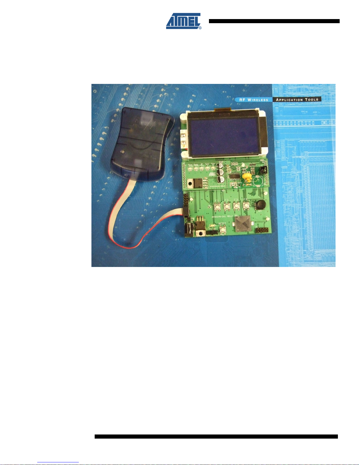
To program the flash memory and the EEPROM, first connect the programming tool to the Main
Board (MB) using a six-pin ribbon connector. The ISP header is the six pins located directly
above the power plug. Make sure that proper orientation is maintained by aligning pin1 to prevent power to ground shorts.
1. Open AVR Studio4 and select "Program AVR", then "Connect..." from the "Tools" menu.
Cancel the welcome screen if necessary.
2. Connect to the STK500 or AVRISP MKII by selecting "STK500 or AVRISP MKII" in the
Platform List. Then select "Connect...".
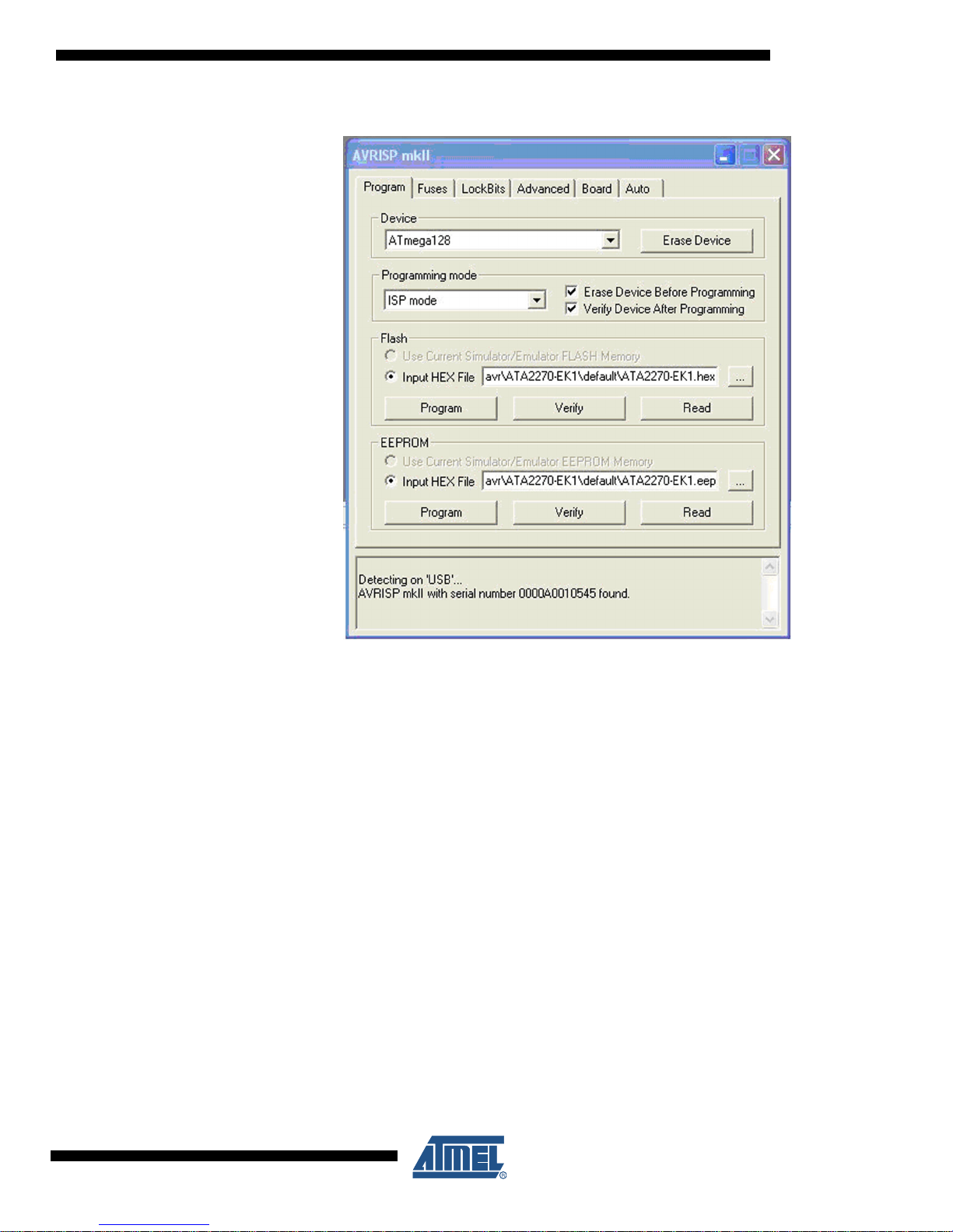
3. The programming dialog box should appear. Note that the system supports other programming platforms as well, like the JTAGICE mkII.
4. Next select the AVR target device (ATmega128) from the pull-down menu on the “Program” tab and locate the Intel-hex file to download. This can be the pre-compiled
firmware that was downloaded from the Atmel web site (or from the CD) or code that
has been customized for a specific application.
5. Select the "program" button.
6. Repeat this procedure with the file containing EEPROM initial values.
2
ATA2220
5241A–RFID–12/07
Page 3
ATA2220
JTAG Programming/Debugging
The same steps apply when using the JTAGICE MKII as a simple programmer. Simply connect
the JTAG 10-pin cable to the MB header, above the ISP connector, and proceed as detailed in
the ISP section.
The benefit of the JTAG Platform is that it allows more control during software development by
allowing real-time debugging of the source code. The JTAGICE MKII supports setting breakpoints and stepping through the code being executed on the target micro in real-time. This is
very useful for a more complex software project such as this one.
To get started, make sure that the latest version of AVR Studio and WinAVR has been installed
on the PC. Download the latest revision of the firmware for the ATA2270-EK1 kit from the Atmel
web site and unzip it to a working folder. Start AVR Studio and click the “Open” button on the
welcome screen. Select the “ATA2270-EK1.aps” file from the working folder.
5241A–RFID–12/07
3
Page 4

This will open up the C complier in AVR Studio and allow development and debugging of the
firmware all from one simple platform. Once opened, this platform displays the source files on
the left (both .c and .h) and allows editing of each file in the main screen. Once the changes
have been made, real-time debugging is achieved by selecting “Build” then “Build and Run” from
the menu. This will compile the source code, flash the target device, and begin code execution.
4
ATA2220
5241A–RFID–12/07
Page 5

ATA2220
Serial Port Bootloader Programming
This section applies only to kits with firmware v3.0 or later already programmed into the microcontroller. The bootloader firmware allows the kit to be upgraded using only the serial port on the
kit. In order to begin, on the ATA2270-EK1 first navigate to the PC>Upgrade Firmware option
and press ENTER. Press ENTER a second time to confirm the desire to enter bootloader mode.
On the PC, open AVR Studio and choose Tools>AVR Prog from the menu. Press the Browse
button and choose the appropriate flash (Intel-hex) file to load. This should have a .hex extension.
5241A–RFID–12/07
5
Page 6

Press the Program button under the Flash section. Answer Yes to the two warning messages
that will appear. These are warnings that the boot section can not be overwritten and that portion
of the file will be ignored.
Again press the Browse button and locate the EEPROM file. This has a .eep extension. Press
the Program button located in the EEPROM section.
Once both of these actions have been successful, pressing the Exit button will leave bootloader
mode. The ATA2270-EK1 should re-start and display the main screen with the newly upgraded
firmware.
6
ATA2220
5241A–RFID–12/07
Page 7

ATA2220
The complete User Guide for the ATA2270-EK1 is available on the Atmel website along with
other Application Notes and Datasheets to help with problems encountered. If you have any
other questions about using the Evaluation Kit or designing with Atmel RFID, please do not hesitate to contact us:
Toby Prescott, North American RFA Applications Engineer, 719-540 6947,
tprescott@cso.atmel.com
Jim Goings, North American RFA Applications Manager, 719-540-6873,
jgoings@cso.atmel.com
Nicolas Schieli, North American RFID Business Development, 514-878-8113 x228,
nschieli@cso.atmel.com
5241A–RFID–12/07
7
Page 8

Revision History
Doc Rev. Date Comments
5241A 12/2007 Initial document release.
8
ATA2220
5241A–RFID–12/07
Page 9

Headquarters International
Atmel Corporation
2325 Orchard Parkway
San Jose, CA 95131
USA
Tel: 1(408) 441-0311
Fax: 1(408) 487-2600
Atmel Asia
Room 1219
Chinachem Golden Plaza
77 Mody Road Tsimshatsui
East Kowloon
Hong Kong
Tel: (852) 2721-9778
Fax: (852) 2722-1369
Product Contact
Web Site
www.atmel.com
Literature Requests
www.atmel.com/literature
Atmel Europe
Le Krebs
8, Rue Jean-Pierre Timbaud
BP 309
78054 Saint-Quentin-enYvelines Cedex
France
Tel: (33) 1-30-60-70-00
Fax: (33) 1-30-60-71-11
Technical Support
rfid@atmel.com
Atmel Japan
9F, Tonetsu Shinkawa Bldg.
1-24-8 Shinkawa
Chuo-ku, Tokyo 104-0033
Japan
Tel: (81) 3-3523-3551
Fax: (81) 3-3523-7581
Sales Contact
www.atmel.com/contacts
Disclaimer: The information in this document is provided in connection with Atmel products. No license, express or implied, by estoppel or otherwise, to any
intellectual property right is granted by this document or in connection with the sale of Atmel products. EXCEPT AS SET FORTH IN ATMEL’S TERMS AND CONDI-
TIONS OF SALE LOCATED ON ATMEL’S WEB SITE, ATMEL ASSUMES NO LIABILITY WHATSOEVER AND DISCLAIMS ANY EXPRESS, IMPLIED OR STATUTORY
WARRANTY RELATING TO ITS PRODUCTS INCLUDING, BUT NOT LIMITED TO, THE IMPLIED WARRANTY OF MERCHANTABILITY, FITNESS FOR A PARTICULAR
PURPOSE, OR NON-INFRINGEMENT. IN NO EVENT SHALL ATMEL BE LIABLE FOR ANY DIRECT, INDIRECT, CONSEQUENTIAL, PUNITIVE, SPECIAL OR INCIDENTAL DAMAGES (INCLUDING, WITHOUT LIMITATION, DAMAGES FOR LOSS OF PROFITS, BUSINESS INTERRUPTION, OR LOSS OF INFORMATION) ARISING OUT
OF THE USE OR INABILITY TO USE THIS DOCUMENT, EVEN IF ATMEL HAS BEEN ADVISED OF THE POSSIBILITY OF SUCH DAMAGES. Atmel makes no
representations or warranties with respect to the accuracy or completeness of the contents of this document and reserves the right to make changes to specifications
and product descriptions at any time without notice. Atmel does not make any commitment to update the information contained herein. Unless specifically provided
otherwise, Atmel products are not suitable for, and shall not be used in, automotive applications. Atmel’s products are not intended, authorized, or warranted for use
as components in applications intended to support or sustain life.
© 2007 Atmel Corporation. All rights reserved. Atmel®, logo and combinations thereof, AVR®, AVRStudio®, STK® and others, are registered
trademarks or trademarks of Atmel Corporation or its subsidiaries. Other terms and product names may be trademarks of others.
5241A–RFID–12/07
Page 10

Mouser Electronics
Authorized Distributor
Click to View Pricing, Inventory, Delivery & Lifecycle Information:
Atmel:
ATA2270-EK1
 Loading...