

Features
1K x 1 Serial E2PROM With Security Logic
•
Available in Two Memory Organizations:
•
AT88SC10111K x 1Memory Zone
AT88SC1022512 x 1Memory Zone
Supports ISO/IEC 7816-3 Synchronous Protocol
•
Stores and Validates Security Codes
•
Counts Incorrect Security Code Attempts
•
Provides Transport Code Security
•
Manufactured Using Low Power CMOS Technology
•
VPP Internally Generated
•
2 µs Read Access Time; 5 ms Write Cycle Time
•
Temperature Range From -25°C to 70°C
•
ESD Immunity > 4K Volts
•
High Reliability:
•
100,000 Write/Erase Cycles
100 Years Data Retention
Smart Card ICs
2
1K E
PROM
with Security
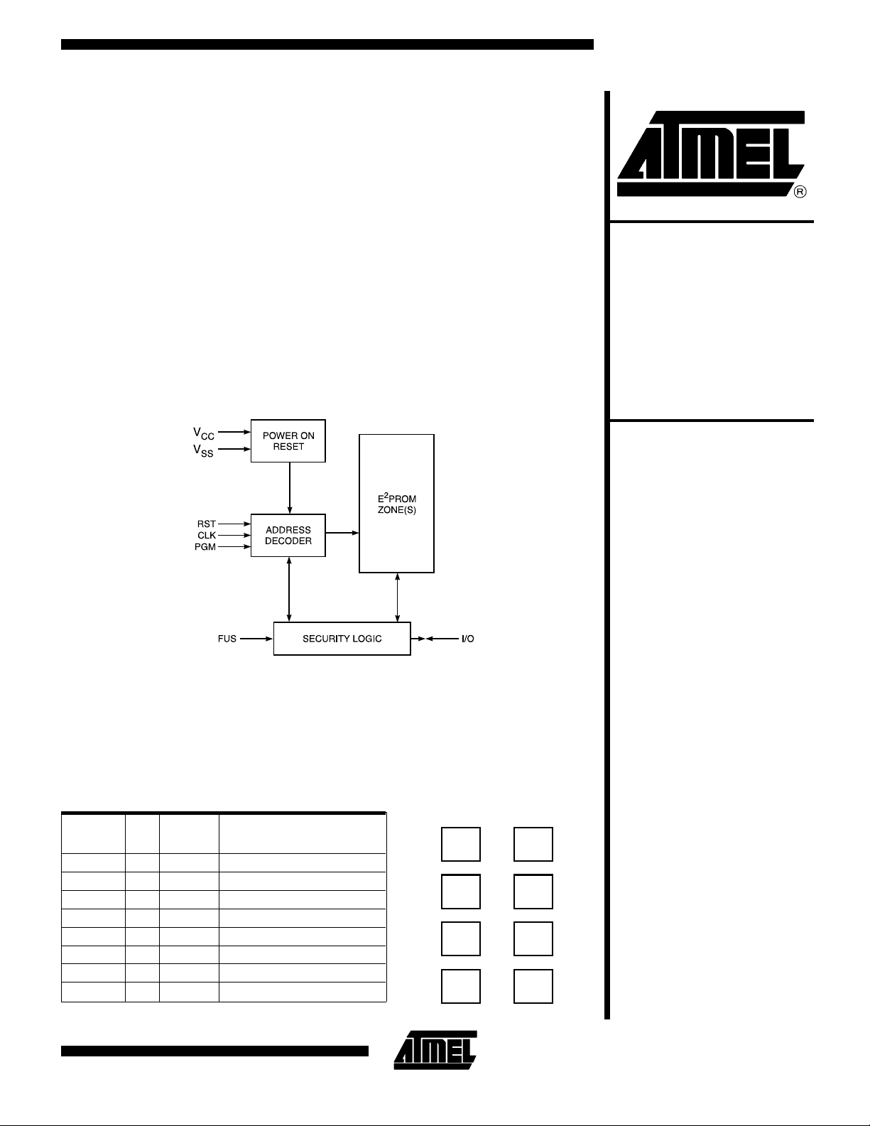
Block D i agr a m
Description
The AT88SC101/102 family provides 1024 bits of serial E2PRO M (Elec tri cally Er asable and P rogrammab le Read Only Memory) with additional secur ity logi c f or use i n
secure smart card applications. The AT88S C101 is available in one 1024 x 1 bit memory zones, and the AT88SC102 is available in two 512 x 1 bit memory zones.
ISO Card Configuration
ISO
Contact
C1 8 V
C2 7 RST Reset
C3 6 CLK Clock and Address Control
C4 5 FUS Identification Fuses
C5 1 V
C6 2 NC No Connect
C7 3 I/O Bi-directional Data Port
C8 4 PGM Programming Control
Pad#Pad
Name
CC
SS
Description
Operating Voltage
Ground
Card Module Contacts
V
RST
CLK
FUS
C1
cc
C2
C3
C4
C5
C6
C7
C8
V
ss
N/C
I/O
PGM
Logic
AT88SC101
AT88SC102
The security features of Atmel’s AT88SC101/102 include:
data ac cess only after validation of the security code
permane nt invalidation of device upon four consecutive
false security code presentations
read/write protection of certain memory zones
device reset if power drops
secure transport of devices using tr ansport code compare
sequence
The AT88SC101/102 is manufactured using low-power
CMOS technology and features its own internal high-voltage pump for single voltage supply operation. The devices are guaranteed to 100,000 erase/w rite cycles and
100 year d ata ret ention. Enduran ce up to one-m illion
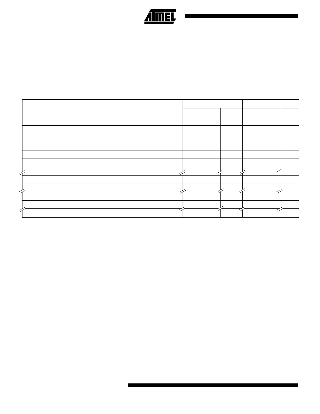
AT88SC101 and AT88SC102 Memory Map
AT88SC101 AT88SC102
Memory Partitions
Fabrication Zone (FZ) 0 - 15 16 0 - 15 16
Issuer Zone (IZ) 16 - 79 64 16 - 79 64
Security Code (SC) 80 - 95 16 80 - 95 16
Security Code Attempts Counter (SCAC) 96 - 111 16 96 - 111 16
Code Protected Zone (CPZ) 112 - 175 64 112 - 175 64
Application Zone 1 (AZ1) 176 - 1199 1024 176 - 687 512
Application Zone 1 Erase Key (EZ1) 1200 - 1231 32 688 - 735 48
Application Zone 2 (AZ2) — — 736 - 1247 512
Application Zone 2 Erase Key (EZ2) — — 1248 - 1279 32
Erase Counter (EC) 1232 - 1359 128 1280 - 1407 128
Memory Test Zone (MTZ) 1360 - 1375 16 1408 - 1423 16
TOTAL BITS 1376 1424
Address Bits Address Bits
Definition of AT88SC101/102 Memory Partitions
FABRICA TION ZONE ( 16 bits): Programmed b y the
manufacturer with a specific identifier for each customer.
FUSE1 is blown by the manufacturer after programming
the fabrication code, which makes the fabrication zone
unalterable.
ISSUER ZONE (64 bits) : Programmed by the issuer before finalizing perso nalization. The data stor ed in the issuer zone is unalterable after FUSE2 is blown.
SECURITY CODE (16 bits): Must be presented by the
issuer to access circuit m emory and personalize device
before blowing FUSE2. This secures transportation between the manufacturer and the issuer. After th e device is
personalized and FUSE2 is blown, this code protects the
access to the application zone(s) of the card.
SECURI TY CODE ATTEMPTS CO UNTER (1 6 bits):
Counts t he number of incorrect secu rity co de attempts.
The device is locked after 4 false presentations.
2
AT88SC101/102
USER PROTECTED ZONE (64 bits): Writing and erasing this zone i s pr otected. The num ber of program/erase
cycles is guaranteed up to 100,000.
AP PLICAT ION ZO NE(S) ( 1024 or 512 bit s): Rea ding
and progr amming the application zone(s) are controlled by
the first 2 bits of the zone (PR, RD) and by the security
code (Tables 1 and 2). The erasure of each zone is protected by an erase key specific to each zone.
APPLICATION ZONE ERASE KEY (32 or 48 bits): Must
be presented to au thorize the era sure of the applicat ion
zone(s). The key(s) must be programmed during the personalization of the circuit.
ERASE COUNTER (128 bits): Limits the number of erasures of the last zone to 128 or less.
MEMORY TEST ZONE (16 bits): Allows pattern testing
at this memory location.

AT88SC101/102
Memory Access to AT88SC101 and AT88SC102
The access to th e me m or y i s control l ed by the stat e of the i nt er nal fu s es and by the voltag e supply a ppl i ed on the FUS pad:
FUS Pad
Voltage
0V Either Either Table 2
5V Blown Not Blown Table 1
5V Blown B lown Table 2
Table 1. AT88SC101/102 Access Conditions During Personalization (FUSE 2 Not Blown)
SC1
Zones
FZ XXXXXXXX YES NO NO NO
IZ 01XXXXXXXXXXXXX
SC 01XXXXXXXXXXXXX
SCAC 01XXXXXXXXXXXXX
CPZ 01XXXXXXXXXXXXX
AZ1 0
0
1
EZ1 01XXXXXXXXXXXXX
AZ2 0
0
1
EZ2 01XXXXXXXXXXXXX
EC 01XXXXXXXXXXXXX
MTZ XXXXXXXX YES YES YES NO
Notes: SC:SC = 1 after validation of security code
1PR:1st bit of AZ1 (Bit 176)
1RD:2nd bit of AZ1(Bit 177)
2PR:1st bit of AZ2 (Bit 736) - AT88SC102 only
1
P
R
R
D
X
0
X
1
X
X
X
X
X
X
X
X
State of the FUSES
FUS E 1 FUS E 2
2
2
E
E
P
R
Z
Z
R
D
1
2
X
X
X
X
X
X
X
X
X
X
X
X
X
0
X
X
X
1
X
X
X
X
X
X
Access Conditions See:
E
C
X
X
X
X
X
X
X
X
X
X
X
X
X
2RD: 2nd bit of AZ2 (Bit 737) - AT88SC102 only
EZ1: EZ1 = 1 after a valid presentation of erase key 1
EZ2: EZ2 = 1 after a valid presentation of erase key 2
EC: EC = 1 when the counter is not empty.
READ WRITE 1
(Erase)
YES
YES
NO
YES
YES
YES
YES
YES
NO
YES
YES
NO
YES
NO
YES
YES
NO
YES
YES
YES
NO
YES
NO
YES
NO
YES
NO
YES
NO
NO
YES
NO
YES
NO
NO
YES
NO
YES
NO
YES
WRITE 0
(PROG)
NO
YES
NO
YES
YES
YES
NO
YES
NO
NO
YES
NO
YES
NO
NO
YES
NO
YES
YES
YES
Compare
NO
NO
YES
NO
NO
NO
NO
NO
NO
NO
NO
NO
NO
NO
NO
NO
NO
NO
NO
NO
3

Table 2. AT88SC101/102 Access Conditions After Personalization (FUSE 2 Blown)
SC1
Zones
FZ XXXXXXXX YES NO NO NO
IZ XXXXXXXX YES NO NO NO
SC 01XXXXXXXXXXXXX
1
2
2
E
E
E
P
R
P
R
Z
Z
C
R
D
R
D
1
2
X
READ WRI TE 1
(Erase)
NO
NO
NO
YES
WRITE 0
(PROG)
NO
YES
Compare
YES
NO
SCAC 01XXXXXXXXXXXXX
X
CPZ 01XXXXXXXXXXXXX
X
AZ1 0
EZ1 XXXXXXXX NO NO NO YES
AZ2 0
EZ2 XXXXXXXX NO NO NO YES
EC XXXXXXXX YES NO YES NO
MTZ XXXXXXXX YES YES YES NO
Notes: SC:SC = 1 after validation of security code
1PR:1st bit of AZ1 (Bit 176)
1RD:2nd bit of AZ1(Bit 177)
2PR:1st bit of AZ2 (Bit 736) - AT88SC102 only
X
0
X
X
X
X
X
0
X
1
X
X
X
X
X
1
0
X
X
X
0
X
X
1
0
X
X
X
1
X
X
1
1
X
X
X
0
X
X
1
1
X
X
X
1
X
X
X
X
X
0
X
X
X
0
X
X
X
1
X
X
X
1
X
X
0
X
X
0
X
1
X
X
0
X
X
X
0
1
X
X
0
X
X
1
1
1
X
X
1
X
X
0
X
1
X
X
1
X
X
X
0
1
X
X
1
X
X
1
1
2RD: 2nd bit of AZ2 (Bit 737) - AT88SC102 only
EZ1: EZ1 = 1 after a valid presentation of erase key 1
EZ2: EZ2 = 1 after a valid presentation of erase key 2
EC: EC = 1 when the counter is not empty.
YES
YES
YES
YES
NO
YES
YES
YES
YES
YES
NO
YES
YES
YES
YES
YES
YES
YES
NO
YES
NO
YES
NO
NO
NO
YES
NO
YES
NO
NO
NO
NO
YES
NO
NO
YES
YES
YES
NO
YES
NO
NO
NO
NO
YES
YES
NO
NO
NO
NO
NO
YES
YES
YES
NO
NO
NO
NO
NO
NO
NO
NO
NO
NO
NO
NO
NO
NO
NO
NO
NO
NO
4
AT88SC101/102
 Loading...