

Page 1
Features
• Compatible with Many Existing Memory Card Applications
• 1-Kbit EEPROM User Memory
– Two256x1ApplicationZones
– One512x1ApplicationZone
– Protected by Security Logic
– Vpp Internally Generated for Single Voltage Operation
– 2 µs Read Access Time
– 2 ms Write Cycle (Self-timed)
• Additional EEPROM Memory for Code Storage
– Three OTP Areas, 144 Bits Total
– 64-bit Code-protected Zone
• Security Features
– Stores and Validates Security Codes
– Maximum of Four Incorrect Security Code Attempts
– Provides Security Code Protection During Transportation
• High Reliability
– Endurance: 100,000 Cycles
– Data Retention: 10 Years
– ESD Protection: 4,000V Minimum
• Manufactured Using Low-power CMOS Technology
• Temperature Range from −25°Cto+85°C
• ISO 7816-compliant Card Modules
Description
The AT88SC1003 is a low-cost synchronous integrated circuit, designed for use in
prepaid and loyalty smart card applications. The AT88SC1003 provides 1024 bits of
serial EEPROM (Electrically Erasable and Programmable Read Only Memory) within
three application zones, plus 64 bits in a code-protected zone. Security logic provides
access protection through use of a 16-bit security code.
Additional EEPROM memory is available to hold unalterable information about the
card history. Separate zones are available for data written by the fabrication facility,
card manufacturer and card issuer. After personalization of the memory by the issuer,
an internal fuse is blown that secures critical memory areas of the device and configures the IC for use by the end customer. The action of blowing this fuse is irreversible.
The AT88SC1003 is manufactured using low-power CMOS technology. EEPROM
programming functions are accomplished using an internally generated high-voltage
pump for single voltage supply operation. Program timing is controlled internally.
Memory endurance is guaranteed to 100,000 erase/write cycles. Ten-year data retention is guaranteed.
Table 1. Pin Configuration
1K Secure
EEPROM
with Three
Application
Zones
AT88SC1003
Pad Description ISO Module Contact
VCC Supply Voltage C1
GND Ground C5
CLK Serial Clock Input C3
I/O Serial Data Input/Output C7
RST Reset Input C2
PGM Program Input C8
FUS Fuse Input C4
Rev. 2035A–SMEM–4/02
1
Page 2
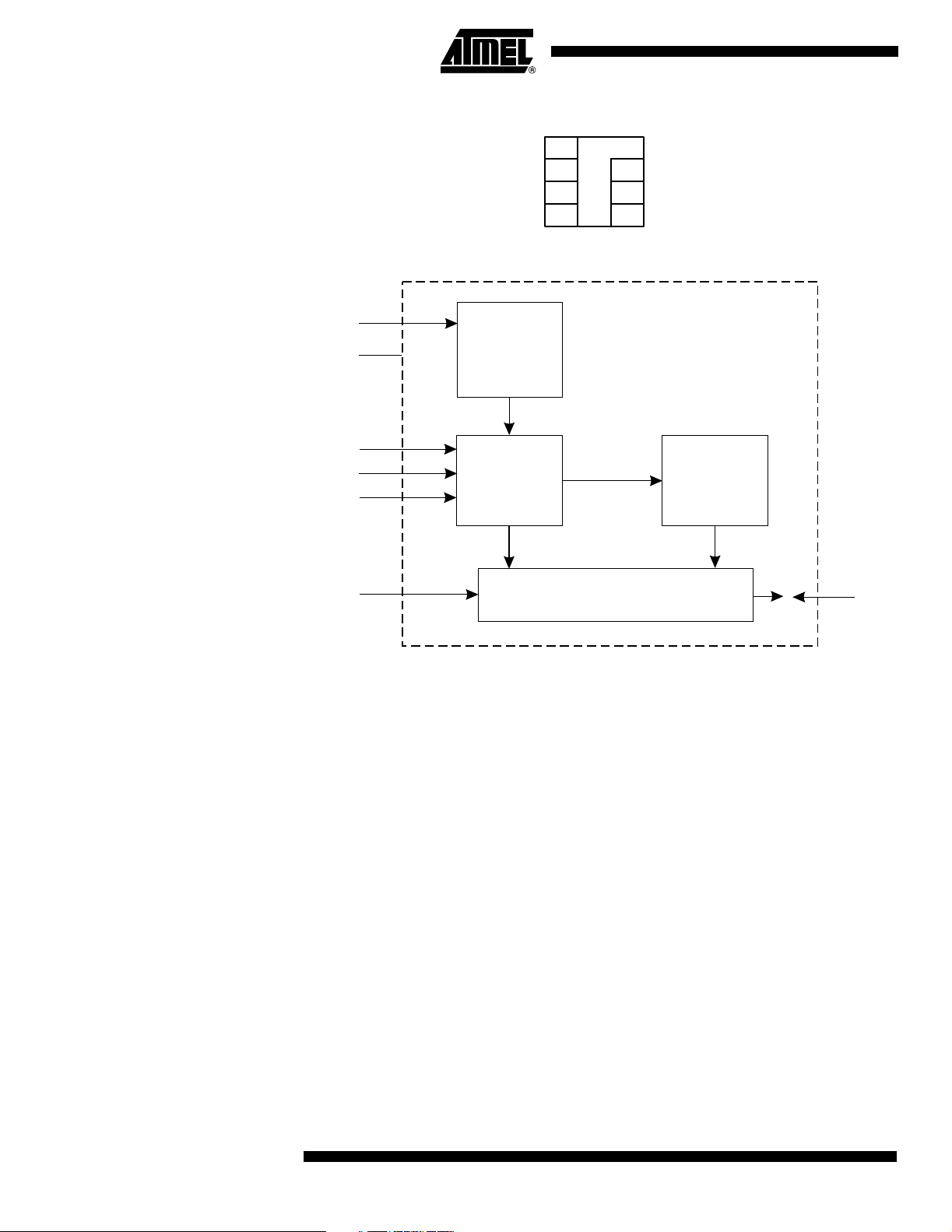
Figure 1. Card Module Contact
Figure 2. Block Diagram
V
CC
GND
RST
CLK
PGM
FUS
V
= C1
CC
RST = C2
CLK = C3
FUS = C4
Power On
Reset
Address
Counter
C5 = GND
C6 = NC
C7 = I/O
C8 = PGM
Security Logic
2
E
PROM
Memory
I/O
Pin Descriptions
Supply Voltage (VCC) The VCC input is a 4.5V to 5.5V positive voltage.
Serial Clock (CLK) The CLK input is used to positive edge clock data into the device and negative edge
clock data out of the device. There is an internal pull-down on CLK.
Serial Data (I/O) I/O is bidirectional for serial data transfer to and from the device.
Reset (RST) The RST input is used to reset the address counter. There is an internal pull-up on RST.
Program (PGM) The PGM input is used to determine the state of I/O as an input or output. There is an
internal pull-down on PGM.
Fuse (FUS) The FUS input is used during the personalization of the device. There is an internal pull-
down on FUS.
2
AT88SC1003
2035A–SMEM–4/02
Page 3
AT88SC1003
Security Features The security features of Atmel’s AT88SC1003 include:
– Data access only after validation of the security code
– Permanent invalidation of device upon four consecutive false security code
presentations
– Read/write protection of certain memory zones
– Secure transport of devices using security code compare sequence.
Security Levels Access to the memory is controlled by the state of the issuer fuse and by the voltage
supply applied on the FUS pin.
FUS Pin Issuer Fuse Security Level
Logic “0” X 2
Logic “1” 1 1
Logic “1” 0 2
Level 1: Security During Personalization by the Card Issuer
Level 2: Security After Personalization (Customer Release)
AT88SC1003 die and modules are delivered with the issuer fuse intact. Issuer personalization is completed at this level. Security code validation is required to allow access to
personalize the EEPROM memory. During personalization, the fab zone fuse may be
blown to lock the fabrication zone. The manufacturer fuse may be blown to lock the
manufacturer’s zone.
See “Memory Access Rules During Personalization” ( Table 2 on page 12).
Conditions:
Issuer fuse = “1” (not blown)
FUS pin = “1” (required)
EEPROM memory zones are protected by the various flags and passwords. After issuer
personalization, Security Level 2 is implemented by blowing the issuer fuse. The device
can also be placed in Security Level 2 by taking the FUS pin low, independent of the
state of the issuer fuse. This function of the FUS pin enables the card issuer to simulate
Security Level 2 during application development, without permanently blowing the
issuer fuse.
See “Memory Access Rules After Personalization” ( Table 3 on page 13).
Conditions:
Issuer fuse = “0” (blown)
FUS pin = “X”
or
Issuer fuse = “1” (not blown)
FUS pin = “0”
2035A–SMEM–4/02
3
Page 4
Memory Diagram
Bit Address Zone Bits Words
0–15 FZ – Fabrication Zone 16 Bits 1
16–79 IZ – Issuer Zone 64 Bits 4
80–95 SC – Security Code 16 Bits 1
96–111 SCAC – Security Code Attempts Counter (only first 4 bits used) 16 Bits 1
112–175 CPZ – Code Protected Zone 64 Bits 4
176–431 AZ1 – Application Zone 1 256 Bits 16
432–479 EZ1 – Application Zone 1 Erase Key 48 Bits 3
480–735 AZ2 – Application Zone 2 256 Bits 16
736–767 EZ2 – Application Zone 2 Erase Key 32 Bits 2
768–895 EC2 – Application Zone 2 Erase Counter 128 Bits 8
896–911 MTZ – Memory Test Zone 16 Bits 1
912–975 MFZ – Manufacturer’s Zone 64 Bits 4
992–1007 ISSUER FUSE 16 Bits 1
1012–1015 FAB ZO NE FUSE 4Bits
1016–1019 MANUF. FUSE – Manufacturer’s Fuse 4 Bits
1020–1023 EC2EN FUSE – Controls use of EC2 4 Bits
1024–1535 AZ3 – Application Zone 3 512 Bits 32
1536–1583 EZ3 – Application Zone 3 Erase Key 48 Bits 3
1584 EB3 – Application Zone 3 Erase Bit 1 Bit
1585–1599 Unused 16 Bits 1
4
AT88SC1003
2035A–SMEM–4/02
Page 5

Memory Zone Descriptions
Zone Definition
AT88SC1003
Fabrication Zone
FZ (16 bits)
Issuer Zone
IZ (64 bits)
Security Code
SC (16 bits)
Security Code Attempts
Counter SCAC
(4 bits plus 12 unused bits)
The 16-bit fabrication zone is initially programmed by Atmel. Prior to blowing the fab zone fuse, the
fabrication zone may be rewritten by the card manufacturer. This area becomes read-only after the
fab zone fuse is blown. Blowing the issuer fuse will also lock the data in the FZ.
The 64-bit issuer zone is programmed by the card issuer during the personalization phase. It will
contain issuer-specific information, such as serial numbers and dates. This area becomes read-only
after the issuer fuse has been blown. Read access is always allowed in the issuer zone.
The security code is initially set by Atmel to protect the product during transportation to the card
issuer. During personalization, this code must be entered and verified by the AT88SC1003 to allow
access to the
changed in either security mode. The security code gives access to Application Zones 1, 2 and 3, and
also gives access to the code-protected zone area for erase and write. Verification of the security
code will set the internal flag SV to “1”. Atmel ships the device with a security code (transportation
code) pre-programmed. This protects against the unauthorized use of an unpersonalized device, and
should be written to a new value during initialization.
The protocol for verification of the security code requires that the user write one of the first four bits of
the SCAC to a logic “0”. This allows the SCAC to count the number of consecutive incorrect
presentations of the security code. After four consecutive incorrect security code presentations, the
first four bits of the SCAC will all be written to “0”, and the user is permanently blocked from access to
the application zones, as well as to other areas controlled by the security code. After a successful
presentation of the security code, the entire 16-bit SCAC, including the four active bits, should be
erased. This verifies that the correct security code has been presented, since an erase operation in
this area is not allowed without SC verification. It also clears the SCAC bits in preparation for the next
use of the card. This erase operation will also clear the remaining 12 bits of the 16-bit SCAC word.
These 12 bits may be used in an application, although the entire 16-bit word will be erased if any bit in
the SCAC is erased.
EEPROM memory. After the security code has been verified, the code itself may be
Code Protected Zone
CPZ (64 bits)
Application Zone 1
AZ1 (256 bits)
ApplicationZone1Erase
Key EZ1 (48 bits)
Read access to this area is always allowed and does not require SC validation. The security code
must be correctly presented to allow write access to the code-protected zone.
AZ1 is intended to hold user application data. P1 (address 176) controls write access and R1
(address 177) controls read access within Zone 1. In Security Level 1, erasing AZ1 is accomplished
by performing an erase operation on any bit within AZ1, after verification of the security code (SV flag
= 1). This operation will erase the entire zone. In Security Level 2, erase operations are controlled by
both the SV flag and the erase key EZ1. See the erase definition in the Device Functional Operation
chart (page 16) for specific details. There is no limit to the number of erase operations performed in
AZ1. In Security Level 1, write operations in AZ1 may be performed on single bits after verification of
the security code. In Security Level 2, the P1 bit must also be set to “1” to allow single bit write
operations. Read operations in Security Levels 1 and 2 are allowed if either R1 is set to “1” or the SV
flag is set to “1” by validating the security code.
The erase keys are passwords used to control erase operations within the application zones, after the
issuer fuse has been blown (Security Level 2). The erase key password is written during
personalization (Security Level 1), after verification of the security code. EZ1 can not be changed
after the issuer fuse is blown. In Security Level 2, AZ1 can be erased only after both the security code
and the EZ1 password have been validated. Verification of EZ1 will set the internal flag E1 to “1”.
2035A–SMEM–4/02
5
Page 6

Memory Zone Descriptions (Continued)
Zone Definition
Application Zone 2
AZ2 (256 bits)
AZ2 is intended to hold user application data. P2 (address 480) controls write access and R2
(address 481) controls read access within Zone 2. In Security Level 1, erasing AZ2 is accomplished
by performing an erase operation on any bit within AZ2, after verification of the security code (SV flag
= 1). This operation will erase the entire zone. In Security Level 2, erase operations are controlled by
the erase key EZ2, the erase counter EC2 and the EC2EN fuse. If the EC2EN fuse is set to “1”, then
the erase counter made for Application Zone 2 is enabled, and the user is limited to 128 erase
operations on AZ2. If the EC2EN fuse is set to “0”, then the erase counter mode is disabled and there
is no limit to the number of erase operations on AZ2. The EC2EN fuse must be written during the
personalization phase (Security Level 1). After the issuer fuse is blown, the status of the EC2EN fuse
cannot be changed. See the erase definition in the Device Functional Operation chart (page 16) for
specific details about erase procedure. In Security Level 1, write operations in AZ2 may be performed
on single bits after verification of the secure code. In Security Level 2, the P2 bit must also be set to
“1” to allow single bit write operations. Read operations in Security Levels 1 and 2 are allowed if either
R2 is set to “1” or the SV flag is set to “1” by validating the secure code.
Application Zone 2
Erase Key EZ2
(32 bits)
Application Zone 2
Erase Counter EC2
(128 bits)
Memory Test Zone
MTZ (16 bits)
Manufacturer’s Zone
MFZ (64 bits)
EC2EN Fuse
(4 bits)
The erase keys are passwords used to control erase operations within application zones after the
issuer fuse has been blown (Security Level 2). The erase key password is written during
personalization (Security Level 1), after verification of the security code. EZ2 cannot be changed after
the issuer fuse is blown. In Security Level 2, AZ2 can be erased only after both the security code and
the EZ2 password have been validated. Verification of EZ2 will set the internal flag E2 to “1”.
The erase counter (EC2) is enabled only in Security Mode 2 and only when the EC2EN fuse is set to
“1”. If both of these conditions are true, the user will be limited to 128 erase operations in Application
Zone 2. EC2 is used to count these erase cycles. The erase protocol for AZ2 requires one bit in EC2
to be written to a “0”. After 128 erase operations in AZ2, all 128 bits in EC2 will be “0” and the user will
be blocked from erasing AZ2. The erase counter is only writeable and cannot be erased. When the
EC2EN fuse = “0”, the EC2 operation is disabled. In that case there is no limit to the number of times
the AZ2 can be erased, and EC2 has no function.
All operations are allowed for this zone (write, erase, read). The purpose of this zone is to provide an
area in the product memory that is not restricted by security logic. It is used for testing purposes
during the manufacturing process and may also be used in the product application if desired, although
no security protection exists for the MTZ.
The MFZ is intended to hold data specific to the smart card manufacturer (like assembly lot codes,
dates, etc.). Read operations within this zone are always allowed. Write or erase operations within this
zone are allowed after the security code has been verified. After the data is entered by the card
manufacturer, the manufacturer’s fuse can be blown and the data within the MFZ will become readonly. Blowing the issuer fuse will also lock the data in the MFZ.
This single bit EEPROM fuse selects whether the EC2 counter is used to limit the number of AZ2
erases in Security Mode 2. If the EC2EN fuse is unblown (“1”), the number of erases of AZ2 is limited
to 128. If the EC2EN fuse is blown (“0”), there is no limit to the number of erase operations in AZ2.
After the issuer fuse is blown, the state of the EC2EN fuse is locked and cannot be changed.
Issuer Fuse
(16 bits)
6
This EEPROM bit functions as a fuse that is used to change the security mode of the AT88SC1003
from Security Mode 1 (“1”), to Security Mode 2 (“0”). Initialization of the IC for use by the end
customer occurs in Security Mode 1. Access conditions in Security Mode 1 are described in Table 2
(page 12). Access conditions in Security Mode 2 are described in Table 3 (page 13).
AT88SC1003
2035A–SMEM–4/02
Page 7

Memory Zone Descriptions (Continued)
Zone Definition
Application Zone 3
AZ3 (512 bits)
AZ3 is intended to hold user application data. P3 (address 1024) controls write access and R3
(address 1025) controls read access within Zone 3. In Security Level 1, erasing AZ3 is accomplished
by performing an erase operation on any bit within AZ3, after verification of the security code (SV flag
= 1). This operation will erase the entire zone. In Security Level 2, erase operations are controlled by
both the SV flag and the erase key EZ3. See the device operation erase definition for specific details.
There is no limit to the number of erase operations performed in AZ3. In Security Level 1, write
operations in AZ3 may be performed on single bits after verification of the security code. In Security
Level 2, the P3 bit must also be set to “1” to allow single bit write operations. Read operations in
Securtiy Levels 1 and 2 are allowed if either R3 is set to “1” or the SV flag is set to “1” by validating the
security code.
AT88SC1003
Application Zone 3
Erase key EZ3
(1 bit)
Application Zone 3
Erase Bit EB3
(1 bit)
Unused
(16 bits)
The erase keys are passwords used to control erase operations within the application zones, after the
issuer fuse has been blown (Security Level 2). The erase key password is written during
personalization (Security Level 1), after verification of the security code. EZ3 can not be changed
after the issuer fuse is blown. In Security Level 2, AZ3 can be erased only after both the security code
and the EZ3 password have been validated. Verification of EZ3 will set the internal flag E3 to “1”.
Address location 1584 is designated as the erase bit for Application Zone 3. The erase protocol for an
AT88SC1003 in Security Mode 2 requires that the erase key (EZ3) be verified, then an erase
operation must be executed on the next bit following the erase key. This action will result in erasing the
entire zone.
Address locations 1585–1599 are not functional in the AT88SC1003. If the address counter is
incremented beyond address 1599, the counter will roll over to address 0. The counter can also be
reset to “0” by executing a reset command.
Terminology The following terms have specific definitions for the AT88SC1003.
– A program operation that results in an EEPROM data bit being set to a logic “1”
Erase
state. Outside the application zones, all erase operations are performed on 16-bit
words. An erase operation performed on any bit within a word will execute an erase of
the entire word. Inside an application zone, erase operations are controlled by the SV
flag, EZ passwords and the EC2EN fuse. These operations are defined in the
Functional Operation
– A program operation that results in an EEPROM bit or word being set to a logic
Write
“0” state. An unwritten bit is defined as erased, or set to a logic “1” state. Write operations in the AT88SC1003 may be performed on individual bits after security code
validation. In Security Level 2, write operations also require that the P1, P2 or P3 bit
within an application zone is set to “1”.
section of this data sheet (page 15).
Device
2035A–SMEM–4/02
Program
– An EEPROM function that activates internally timed, high-voltage circuitry
and results in a data bit or word being set to either a logic “0” or “1” state.
– A single data element set to either a logic “0” or “1” state. All bit addresses within
Bit
the application zones (AZ1, AZ2, AZ3) may be written individually.
– Eight consecutive data bits. A byte boundary will begin on an address that is
Byte
evenly divisible by 8. The AT88SC1003 has no capability for byte write operations.
– Sixteen consecutive data bits. A word boundary will begin on an address that is
Word
evenly divisible by 16. The AT88SC1003 will allow words to be written to a “0” during
personalization (Security Level 1). Erase operations will always operate on 16-bit words
when applied to addresses outside the application zones.
7
Page 8

Blown – In reference to AT88SC1003 internal EEPROM fuses, the blown state is a logic
“0”.
Unblown
logic “1”.
Verification
flags. The flags SV, E1, E2 and E3 are set after verification of an associated password
(security code; EZ1, EZ2 and EZ3 respectively). Verification is accomplished by executing an INC/CMP operation, which correctly matches the password bit by bit as the CLK
increments the address through the password memory addresses.
– In reference to AT88SC1003 internal EEPROM fuses, the unblown state is a
– AT88SC1003 operations are controlled by the state of several internal
8
AT88SC1003
2035A–SMEM–4/02
Page 9

Definition of AT88SC1003 Internal Flags
Flag Definition
SV Security Validation flag
OPERATION:
The SV flag is set by correctly matching the 16-bit security code bit by bit from address 80 through 95, as pin CLK
increments the address counter. The security code matching operation must be followed immediately by a validation
operation within the Security Code Attempts Counter (SCAC). This validation operation requires the user to find a bit
in the SCAC, Addresses 96–99, that is a logic “1”. A write is performed followed by an erase. The AT88SC1003 will
validate that the comparison was correct by outputting a logic “1”, and SV will be set. After the erase, all 16 bits in the
SCAC will also be erased. The flag remains set until power to the card is turned off. If the comparison was in error or
part of the validation was not performed correctly, the AT88SC1003 will output a logic “0” showing that SV has not
been set. After four consecutive incorrect security code presentations, the card is permanently locked.
FUNCTION:
This flag is the master protection for the memory zones. See Tables 1 and 2.
P1 Application Zone 1 write flag
OPERATION:
If Bit 176 has been programmed to a logic “1”, this flag is set after Bit 176 has been addressed. The flag remains set
until power to the device is turned off, even if this bit is written to “0” by a subsequent operation.
FUNCTION:
P1 and SV must both be set in order to enable a write command in Application Zone 1 (Security Mode 2).
AT88SC1003
P2 Application Zone 2 write flag
OPERATION:
If Bit 480 has been programmed to a logic “1”, this flag is set after Bit 480 has been addressed. The flag remains set
until power to the device is turned off, even if this bit is written to “0” by a subsequent operation.
FUNCTION:
P2 and SV must both be set in order to enable the write command in Application Zone 2 (Security Mode 2).
P3 Application Zone 3 write flag
OPERATION:
If Bit 1024 has been programmed to a logic “1”, this flag is set after Bit 1024 has been addressed. The flag remains
set until power to the device is turned off, even if this bit is written to “0” by a subsequent operation.
FUNCTION:
P3 and SV must both be set in order to enable a write command in Application Zone 3 (Security Mode 2).
R1 Application Zone 1 read flag
OPERATION:
If Bit 177 has been programmed to a logic “1”, this flag is set after Bit 177 has been addressed. The flag remains set
until power to the device is turned off, even if this bit is written to “0” by a subsequent operation.
FUNCTION:
R1 or SV must be set to “1” in order to enable Application Zone 1 bits to be read.
R2 Application Zone 2 read flag
OPERATION:
If Bit 481 has been programmed to a logic “1”, this flag is set after Bit 481 has been addressed. The flag remains set
until power to the device is turned off, even if this bit is written to “0” by a subsequent operation.
FUNCTION:
R2 or SV must be set to “1” in order to enable Application Zone 2 bits to be read.
R3 Application Zone 3 read flag
OPERATION:
If Bit 1025 has been programmed to a logic “1”, this flag is set after Bit 1025 has been addressed. The flag remains
set until power to the device is turned off, even if this bit is written to “0” by a subsequent operation.
FUNCTION:
R3 or SV must be set to “1” in order to enable Application Zone 3 bits to be read.
2035A–SMEM–4/02
9
Page 10

Definition of AT88SC1003 Internal Flags (Continued)
Flag Definition
E1 Application Zone 1 erase flag
OPERATION:
E1 is set when the Application Zone 1 erase code comparison is valid.
This flag is reset when the address counter = 0.
FUNCTION:
Application Zone 1 (Bits 176–431) is erased when E1 is set and an erase is performed on Bit 480. This operation
erases all bits in Application Zone 1 but does not affect the word containing Bit 480.
E2 Application Zone 2 erase flag with erase counter operation enabled. (EC2EN FUSE = “1”)
OPERATION:
This flag is set by correctly matching the Application Zone 2 erase code (EZ2) bit by bit as CLK increments the
address counter. A validation operation must then be completed. This operation requires the user to find a bit in the
Application Zone 2 erase counter (EC2), Addresses 768–895, that is a logic “1”. A write must then be performed,
followed by an erase. The part will validate that the comparison was correct and Application Zone 2 will be erased. It
is reset when the address counter = 0.
FUNCTION:
Application Zone 2 (Bits 480–735) is erased when E2 is set and an erase is performed after the validation operation
in EC2 described above. This operation erases all bits in Application Zone 2.
E2 Application Zone 2 erase flag with erase counter operation disabled. (EC2EN FUSE = “0”)
OPERATION:
E2 is set when the Application Zone 2 erase code comparison is valid.
This flag is reset when the address counter = 0.
FUNCTION:
Application Zone 2 (Bits 480–735) is erased when E2 is set and an erase is performed on Bit 768. This operation
erases all bits in Application Zone 2 but does not affect the word containing Bit 768.
E3 Application Zone 3 erase flag
OPERATION:
E3 is set when the Application Zone 3 erase code comparison is valid.
This flag is reset when the address counter = 0.
FUNCTION:
Application Zone 3 (Bits 1024–1535) is erased when E3 is set and an erase is performed on Bit 1584. This operation
erases all bits in Application Zone 3.
10
AT88SC1003
2035A–SMEM–4/02
Page 11

Definition of AT88SC1003 Passwords
Password Definition
AT88SC1003
Security Code (SC)
Bits 80–95
(16 bits)
Erase Zone 1 (EZ1)
Bits 432–479
(48 bits)
Erase Zone 2 (EZ2)
Bits 736–767
(32 bits)
Erase Zone 3 (EZ3)
Bits 1536–1583
(48 bits)
This password is used to set the SV (Security Validation) flag and is used in determining what
operations are allowed in each zone.
This password must be programmed during issuer personalization. It is used to erase Application
Zone 1 in Security Level 2. Verification of EZ1 will set the internal flag E1 to “1”.
This password must be programmed during issuer personalization. It is used to erase Application
Zone 2 in Security Level 2. Verification of EZ2 will set the internal flag E2 to “1”.
This password must be programmed during issuer personalization. It is used to erase Application
Zone 3 in Security Level 2. Verification of EZ3 will set the internal flag E3 to “1”.
Definition of AT88SC1003 Fuses
Fab Zone Fuse This fuse is used to control writes and erases of the fab zone. When the security code
has been validated and both the issuer fuse and the fab zone fuse are unblown, writes
and erases of the fab zone are allowed. Blowing the issuer fuse will also disable the fab
zone fuse if it has not been blown previously.
Manufacturer Fuse This fuse is used to control writes and erases of the manufacturer’s zone. When the
security code has been validated and both the issuer fuse and the manufacturer fuse
are unblown, writes and erases of the MFZ are allowed. Blowing the issuer fuse will also
disable the manufacturer fuse if it has not been blown previously.
EC2EN Fuse The EC2 enable fuse selects whether the EC2 zone is used to limit the number of AZ2
erases allowed in Security Mode 2. If the EC2EN fuse is “unblown,” then the AZ2 erases
are limited to 128. If EC2EN fuse is “blown,” the AZ2 erases are unlimited. After the
issuer fuse is blown, the state of EC2EN fuse is locked and cannot be changed.
Issuer Fuse This fuse is used to personalize the AT88SC1003 for end customer use. It is an addi-
tional EEPROM bit that can be programmed to a logic “0”. This is its “blown” state.
Security of the device when the issuer fuse is a logic “1” is described in Table 2 on page
12. The device is in Security Level 2 when the issuer fuse is blown. The device can also
be placed in Security Level 2 by taking FUS pin low, independent of the state of the
issuer fuse. Memory access rules of the device in Security Level 2 are described in
Table 3 on page 13.
2035A–SMEM–4/02
11
Page 12

Table 2 . Memory Access Rules During Personalization (Security Level 1)
EC2EN = “X”; Issuer Fuse = “1” and FUS Pin = “1”
Zone SV
(1)
R1
(2)
R2
(3)
R3
(4)
MF
(5)
FF
(6)
Read Erase Write Compare
FZ
IZ
SC
SCAC
CPZ
AZ1
EZ1
AZ2
EZ2
EC2
0
x
1
0
1
0
1
0
1
0
1
0
0
1
0
1
0
0
1
0
1
0
1
x
x
x
x
x
x
x
x
x
x
x
0
1
x
x
x
x
x
x
x
x
x
x
x
x
x
x
x
x
x
x
x
x
x
x
x
x
x
x
0
1
x
x
x
x
x
x
x
x
x
x
x
x
x
x
x
x
x
x
x
x
x
x
x
x
x
x
x
x
x
x
x
x
x
x
x
x
x
x
x
x
x
x
x
x
x
x
x
x
x
x
x
x
0
1
x
x
x
x
x
x
x
x
x
x
x
x
x
x
x
x
x
x
x
x
yes
yes
yes
yes
yes
no
yes
yes
yes
yes
yes
no
yes
yes
no
yes
no
yes
yes
no
yes
yes
yes
no
no
yes
no
yes
no
yes
no
yes
no
yes
no
no
yes
no
yes
no
no
yes
no
yes
no
yes
no
no
yes
no
yes
no
yes
yes
yes
no
yes
no
no
yes
no
yes
no
no
yes
no
yes
yes
yes
no
no
no
no
no
yes
no
no
no
no
no
no
no
no
no
no
no
no
no
no
no
no
no
MTZxxxxxxyesyesyes no
no
no
no
no
no
no
no
no
MFZ
AZ3
EZ3
0
x
1
0
0
1
0
1
x
x
x
x
x
x
x
x
x
x
x
x
x
x
x
x
x
x
x
0
1
x
x
x
x
0
1
x
x
x
x
x
x
x
x
x
x
x
x
x
yes
yes
yes
no
yes
yes
no
yes
no
no
yes
no
no
yes
no
yes
no
no
yes
no
no
yes
no
yes
Notes: 1. SV = “1” after validation of the security code
2. 2nd bit of the Application Zone 1 (Bit 177)
3. 2nd bit of the Application Zone 2 (Bit 481)
4. 2nd bit of the Application Zone 3 (Bit 1025)
5. Manufactuer fuse = “0” when blown.
6. Fab zone fuse = “0” when blown.
12
AT88SC1003
2035A–SMEM–4/02
Page 13

AT88SC1003
Table 3 . Memory Access Rules After Personalization (Security Level 2)
Manufacturer Fuse = “X”; EC2EN Fuse = “1” or “0”; Issuer Fuse = “0” or FUS Pin = “0”
Zone SV
(1)
FZxxxxxxxxx xyesno no no
IZxxxxxxxxx xyes no no no
P1
(2)
R1
(3)
P2
(4)
R2
(5)
P3
(6)
R3
(7)
E1
(8)
E2
(9)
E3
(10)
Read Erase Write Compare
SC
SCAC
CPZ
AZ1
0
1
0
1
0
1
0
0
1
1
1
1
x
x
x
x
x
x
x
x
0
0
1
1
x
x
x
x
x
x
0
1
x
x
x
x
x
x
x
x
x
x
x
x
x
x
x
x
x
x
x
x
x
x
x
x
x
x
x
x
x
x
x
x
x
x
x
x
x
x
x
x
x
x
x
x
x
x
x
x
x
x
x
x
x
x
x
x
x
x
x
x
0
1
0
1
x
x
x
x
x
x
x
x
x
x
x
x
x
x
x
x
x
x
x
x
x
x
x
x
no
no
yes
yes
yes
yes
no
yes
yes
yes
yes
yes
no
yes
no
yes
no
yes
no
no
no
yes
no
yes
no
yes
yes
yes
no
yes
no
no
no
no
yes
yes
yes
no
no
no
no
no
no
no
no
no
no
no
EZ1xxxxxxxxx xno no no yes
AZ2
0
0
1
1
1
1
x
x
x
x
x
x
x
x
x
x
x
x
x
x
0
0
1
1
0
1
x
x
x
x
x
x
x
x
x
x
x
x
x
x
x
x
x
x
x
x
x
x
x
x
0
1
0
1
x
x
x
x
x
x
no
yes
yes
yes
yes
yes
no
no
no
yes
no
yes
no
no
no
no
yes
yes
no
no
no
no
no
no
EZ2xxxxxxxxx xno no no yes
EC2xxxxxxxxx xyes no yes no
MTZxxxxxxxxx xyesyesyes no
MFZxxxxxxxxx xyes no no no
AZ3
0
0
1
1
1
1
x
x
x
x
x
x
x
x
x
x
x
x
x
x
x
x
x
x
x
x
x
x
x
x
x
x
0
0
1
1
0
1
x
x
x
x
x
x
x
x
x
x
x
x
x
x
x
x
x
x
0
1
0
1
no
yes
yes
yes
yes
yes
no
no
no
yes
no
yes
no
no
no
no
yes
yes
no
no
no
no
no
no
EZ3xxxxxxxxx xno no no yes
Notes: 1. SV = “1” after validation of the security code
2. 1st bit of the Application Zone 1 (Bit 176)
3. 2nd bit of the Application Zone 1 (Bit 177)
4. 1st bit of the Application Zone 2 (Bit 480)
5. 2nd bit of the Application Zone 2 (Bit 481)
6. 1st bit of the Application Zone 3 (Bit 1024)
7. 2nd bit of the Application Zone 3 (Bit 1025)
8. E1 = “1” after a valid presentation of EZ1.
9. E2 = “1” after a valid presentation of EZ2.
10. E3 = “1” after a valid presentation of EZ3.
2035A–SMEM–4/02
13
Page 14

Micro Operations The AT88SC1003 circuit micro operation modes are selected by the input logic levels on
the control pins PGM, RST and CLK and by the internal address. Timing for these operations is specified in the
Operation PGM RST CLK Definition
RESET
INC/READ 0 0
INC/CMP 0 0
X0
AC Characteristics
The internal address is reset to “0”. After the falling edge of
RST, the first bit of the fabrication zone (Bit 0) will be driven
on the I/O contact. All erase flags (E1, E2, E3) are reset.
The address is incremented on the falling edge of CLK. If
read operations are enabled, the addressed bit will be
driven on the I/O contact after the falling edge of CLK. This
data is valid until the next falling edge of CLK, except for the
bits immediately preceding the security code and erase
keys. For these bits, the data is valid only while CLK is low.
When CLK goes high, the I/O line will be disabled (high
impedence). This will allow data to be set up on the I/O line
before comparing the first bit of each code. When read
operations are disabled, the I/O will be disabled and pulled
to a high state by the external system pullup resistor.
The INC/CMP operation will compare the value of the data
driven by the system host on the I/O pin, to the value of the
bit already written to the EEPROM memory at that address
location. This process is used during validation of the
AT88SC1003 security code and passwords. The data must
be stable on the I/O pin before the falling edge of CLK,
when the data will be latched internally. Comparison occurs
on the next falling edge of CLK. The address is
incremented on the falling edge of CLK.
section (page 20).
The I/O pin must be driven to a “1” for an erase and to a “0”
for a write operation before the rising edge of CLK. CLK
ERASE/WRITE 1 0
STANDBY 0 1 X
Note: The two instructions INC/READ and INC/CMP share the same control signal states. The circuit will distinguish between the two
instructions by testing the internal address counter. (CMP can only be done with the addresses corresponding to the security
code or to the erase keys.) The internal address counter counts up to 1599. An additional CLK pulse resets the address to “0”.
must be held high for at least 2 ms. After the falling edge of
CLK, the data written to the EEPROM will be driven by the
AT88SC1003 on the I/O pin.
The device is placed in standby mode when FUS = “0” and
RST = “1”. The address counter will not increment when
RST is high.
14
AT88SC1003
2035A–SMEM–4/02
Page 15

Device Functional Operation
Function Functional Operation Sequence
POR OPERATION:
POR (power on reset) is initiated as the device power supply ramps from 0V up to a valid operating voltage.
FUNCTION:
POR resets all flags, and the address is reset to “0”.
RESET OPERATION:
With CLK low, a falling edge on the RST pin will reset the address counter to address 0.
FUNCTION:
The address is reset to “0”, and the first bit of the memory is driven by the AT88SC1003 on I/O after a reset. E1,
E2 and E3 are reset when the address is reset to “0”. The reset operation has no effect on any of the other flags
(SV,P1,P2,P3,R1,R2,R3).
ADDRESSING OPERATION:
Addressing is handled by an internal address counter. The address is incremented on the falling edge of CLK.
Reset must be low while incrementing the address. The falling edge of reset clears the counter to address “0”.
FUNCTION:
Addressing of the AT88SC1003 is sequential. Specific bit addresses may be reached by completing a reset, then
clocking the device (INC/READ) until the desired address is reached. The AT88SC1003 will determine which
operations are allowed at specific address locations. These operations are specified in Tables 1 and 2.
EXAMPLE:
To address the Issuer Zone (IZ), execute a reset operation, then clock the device 16 times. The device now
outputs the first bit of the IZ. After the address counter counts up to 1599, the next CLK pulse resets the address
to “0”.
AT88SC1003
READ OPERATION:
RST and PGM pins must be low. If a read operation is allowed, the state of the memory bit being addressed is
output on the I/O pin. The I/O buffer is an open drain and the output of a logic “0”, which therefore causes the
device to pull the pin to ground. The output of a logic “1” causes the device to place the pin in a high impedance
state. Therefore, in order to sense a logic “1”, an external pullup must be placed between the I/O pin and VCC.
The address counter is incremented on the falling edge of CLK.
FUNCTION:
NON-APPLICATION ZONES:
As the address is incremented, the contents of the memory are read out on the I/O pin. The read operation is
inhibited for addresses where security prevents a read operation (see Tables 1 and 2).
APPLICATION ZONES:
The application zones can be read when: SV = “1” or R1(AZ1) / R2(AZ2) / R3(AZ3) = “1”
FUSE READ OPERATION:
When the FUS pin is high, the state of the various fuses can be read when addressing the corresponding bits in
the memory.
FUNCTION:
To verify the state of the fuses.
2035A–SMEM–4/02
15
Page 16

Device Functional Operation (Continued)
Function Functional Operation Sequence
WRITE A write operation sets the bit(s) to a logic “0”.
OPERATION:
CLK = “0”
PGM “0”
I/O = “0” (Input = “0” for write operation)
CLK “0”
PGM “1”
I/O “0”
Wait Tchp (see
CLK “1” → "0" (falling edge of CLK ends the write operation)
Note: The falling edge of CLK that ends the write operation does not increment the address counter.
FUNCTION:
NON-APPLICATION ZONES:
The write operation is inhibited for addresses where security prevents a write operation
(see Tables 1 and 2).
APPLICATION ZONES:
The application zones can be written when:
Security Level 1: SV = “1”
Security Level 2: SV = “1” and P1(AZ1)/P2(AZ2)/P3(AZ3) = “1”
→ “1” (I/O switches to an input)
→ “1” (rising edge of CLK starts the write operation)
→ “0”
→ “Z” (high impedance)
AC Electrical Characteristics)
ERASE
Operation
Sequence
ERASE
(Nonapplication
Zones)
ERASE
AZ1, AZ2 and
AZ3
Security Mode 1
CLK = “0”
PGM “0”
I/O = “1” (input = “1” for erase operation)
CLK “0”
PGM “1”
I/O “0”
Wait Tchp (See
CLK “1” → “0” (falling edge of CLK ends the erase operation)
Note: The falling edge of CLK that ends the erase operation does not increment the address counter.
An erase operation sets the bits to logic “1”. The EEPROM memory is organized into 16-bit words. Although
erases are performed on single bits, the erase operation clears an entire word in the memory (except for the
Application Zones AZ1, AZ2 and AZ3 in Security Level 2). Therefore, performing an erase on any bit in the word
will clear
OPERATION:
Perform “Erase Operation Sequence” as specified above.
FUNCTION:
The erase operation is inhibited for addresses where security prevents an erase operation (see Tables 1 and 2).
Security Level 1: (
Application Zones 1, 2 and 3 can be erased when: SV = “1”
OPERATION:
Increment address counter to any bit within AZ1, AZ2 or AZ3.
Perform “Erase Operation Sequence” as specified above.
FUNCTION: This operation will erase the entire application zone.
→ “1” (I/O switches to an input)
→ “1” (rising edge of CLK starts the erase operation)
→ “0”
→ “Z” (high impedance)
AC Electrical Characteristics)
all
16 bits of that word to logic “1”.
Issuer fuse =
“1”
and FUS pin =
“1”)
16
AT88SC1003
2035A–SMEM–4/02
Page 17

Device Functional Operation (Continued)
Function Functional Operation Sequence
ERASE
AZ1 and AZ3
Security Mode 2
ERASE
AZ2
Security Mode 2
EC2 Mode
Enabled
Security Level 2 (
SV = “1” and E1 (AZ1)/E3 (AZ3) = “1”
OPERATION:
Increment address counter to the first bit of the application zone erase key (EZ1 = Bit 432, EZ3 = Bit 1536).
Execute 48 INC/CMP operations, correctly verifying each bit of the 48-bit erase key.
Increment the address counter to the next bit (Bit 480 for AZ1, Bit 1584 for AZ3).
Perform “Erase Operation Sequence” as specified above.
FUNCTION: This operation will erase the entire application zone.
Security Mode 2: (
EC2 mode is enabled. Erase operations within Zone 2 limited to 128.
OPERATION:
Increment address counter to the first bit of the application zone erase key (EZ2 = Bit 736).
Execute 32 INC/CMP operations, correctly verifying each bit of the 32-bit erase key.
Increment the address counter through the Application Zone 2 erase counter (EC2 = Bits 768–895) until a bit is
found that is set to “1”. Perform a write operation on this bit (this write will not increment the address counter).
Perform an erase operation on the same bit.
FUNCTION: This operation will erase the entire application zone.
Issuer Fuse = “0”
EC2EN = “1” and
or FUS pin =
Issuer Fuse = “0”
“0”
)
or FUS pin =
“0”
AT88SC1003
)
ERASE
AZ2
Security Mode 2
EC2 Mode
Disabled
Blowing
Fab Zone Fuse
Security Mode 2 (EC2EN = “0” and Issuer Fuse = “0”
EC2 mode is disabled. Unlimited erase operations in Zone 2.
OPERATION:
Increment address counter to the first bit of the application zone erase key (EZ2 = Bit 736).
Execute 32 INC/CMP operations, correctly verifying each bit of the 32-bit erase key.
Increment the address counter to the next bit (Bit 768).
Perform “Erase Operation Sequence” as specified above.
FUNCTION: This operation will erase the entire application zone.
Fab zone fuse must be blown before issuer fuse is blown.
Set address between Addresses 1012 and 1015.
SV must be set.
“0”
The FUS pin can be either a
RST pin =
Perform a write operation.
Fab zone fuse will be at a logic
“0”
or a “1”.
“0”
state.
or FUS pin =
“0”
)
2035A–SMEM–4/02
17
Page 18

Device Functional Operation (Continued)
Function Functional Operation Sequence
Blowing
Manufacturer
Fuse
Set address counter between Address 1016 and 1019.
SV must be set.
The FUS pin can be either a “0” or a “1”.
RST pin = “0”
Perform a write operation.
Manufacturer fuse will be at a logic “0” state.
Blowing
EC2EN Fuse
Blowing Issuer
Fuse
EC2EN fuse must be blown before issuer fuse is blown.
SV must be set.
Set address between Address 1020 and 1023.
FUS pin = “1”
RST pin = “0”
Perform a write operation.
EC2EN fuse will be at a logic “0” state.
Set address counter between Address 992 and 1007.
SV must be set.
The FUS pin can be either a “0” or a “1”.
RST pin = “0”
Perform a write operation.
Issuer fuse will be at a logic “0” state.
18
AT88SC1003
2035A–SMEM–4/02
Page 19

AT88SC1003
Electrical Characteristics
Absolute Maximum Ratings*
Operating Temperature ....................... −55°C to +100°C
Storage Temperature........................... −65°C to +100°C
Volt a ge on A ny Pin
with Respect to Ground...................−0.3V to V
CC
+0.7V
Maximum Operating Voltage .................................6.25V
DC Output Current................................................5.0 mA
DC Characteristics
Applicable over recommended operating range from: V
(unless otherwise noted).
Symbol Parameter Test Condition Min Typ Max Unit
CC
*NOTICE: Stresses beyond those listed under “Absolute Maxi-
mum Ratings” may cause permanent damage to the
device. This is a stress rating only and functional operation of the device at these or any other conditions
beyond those indicated in the operational sections of
this specification is not implied. Exposure to absolute
maximum rating conditions for extended periods may
affect device reliability.
= 4.5V to 5.5V and TA= −25°C to +85°C
I
CC
I
CCP
I
SB
V
V
V
I
LI
I
LO
IL
IH
OL
Supply Current on VCCduring Read (TA=+25°C) – – 2 mA
Supply Current on VCCduring Program (TA=+25°C) – – 5 mA
Standby Current on V
RST @ V
CC
FUS, CLK, PGM @ GND. IOL= 0 µA. F
Input Low Level −0.3 – V
CC
CLK
= 0 kHz)
– – 50 µA
x 0.3 V
CC
Input High Level VCCx0.7 – VCC+0.3 V
Output Low Level (IOL=1mA) – – 0.4 V
Input Leakage Current – – 100 µA
I/O Leakage Current (VOH=VCCopen drain) – – 20 µA
2035A–SMEM–4/02
19
Page 20

AC Characteristics
T
= −25°C to +85°C, VCC= 5V ± 10%, GND = 0V (unless otherwise noted)
A
Characteristics Symbol Min Typ Max Unit
Clock Cycle Time t
RST Hold Time t
Data Valid Reset to Address “0” t
CLK Pulse Width (High) t
CLK Pulse Width (Low) t
Data Access t
Data Hold t
Data In Setup (CMP Instruction) t
Data In Hold (CMP Instruction) t
CLK Pulse Width (High in Programming) t
Data In Setup t
Data In Hold t
PGM Setup t
PGM Hold t
Conditions of Dynamic Tests
The circuit has an output with open drain. An external resistor is necessary between
VCC and I/O in order to load the output.
CLK
RH
DVR
CH
CL
DV
OH
SC
HC
CHP
DS
DH
SPR
HPR
Pulse Levels of the Input VSSto V
3.3 – – µs
0.1 – – µs
––2.0µs
0.2 – – µs
0.2 – – µs
––2.0µs
0––µs
0––ns
0.2 – – µs
2.0 – – ms
0.2 – – µs
0––µs
2.2 – – µs
0.2 – – µs
CC
Reference Levels in Input VCCx0.3andVCCx0.7
Reference Levels in Output 1.5V
Rising and Falling Time of Signals 5 ns
Figure 3. AC Load Circuit
VCC
R
LOAD
Test
Point
100 pF
Test Ckt.
Included
CHIP
I/O
20
AT88SC1003
2035A–SMEM–4/02
Page 21

Timing Diagrams
AT88SC1003
Figure 4. Reset
Address
CLK
t
RH
RST
I/O
Note: CLK should be low on the falling edge of RST. CLK may remain low while RST is pulsed.
0 (internal address counter)
t
DVR
Data ValidOutput
Figure 5. Inc/Read
t
CLK
Address
t
CL
t
CH
CLK
t
OH
I/O
t
DV
Note: PGM and RST must both be low during a read cycle.
I/O should not be driven (except by the external pullup resistor).
t
OH
2035A–SMEM–4/02
21
Page 22

Figure 6. Erase/Write
Read Erase/Write Read
Address
A
n-1
A
n
A
n
t
CHP
A
n
A
n+1
CLK
t
t
SPR
HPR
t
DV
PGM
I/O
t
DV
t
OH
Valid
Output
t
DS
Drive
"1" (Erase)
or "0" (Write)
Input
t
DH
Valid
Output
Note: During any erase or write operation, PGM must fall before the falling edge of CLK at the
end of t
After the rising edge of PGM to initiate the erase/write operation, delay at least t
(recommend a minimum setup time of 1 usec).
CHP
DV
usec) before driving data on the I/O contact.
Figure 7. Compare
Address
A
n-1
A
n
A
n+1
(2
CLK
t
SC
I/O
Input
Note: Input data is latched on the falling edge of CLK.
Comparison occurs on the next falling edge of CLK.
The address counter is incremented on the falling edge of CLK.
t
HC
t
SC
22
AT88SC1003
2035A–SMEM–4/02
Page 23

Figure 8. INC/CMP (before code presentation)
AT88SC1003
Address
A
n-1
A
n
A
n+1
CLK
t
SC
I/O
Note: After the rising edge of CLK on the address immediately preceding the security code or
Output
erase keys, the I/O will be disabled (Hi-Z). This allows the input data to be set up before
comparing the first bit of each code.
Hi-Z
Input
t
HC
t
SC
2035A–SMEM–4/02
23
Page 24

24
AT88SC1003
Address
RST
CLK
Reset
A
Figure 9. Security Code Validation
Read
A
A
x
A
0
1
A
2
79
Compare SC
A
A
80
81
A
A
95
94
A
96
Read SCAC
(B) (C) (D) (E) (F) (G)(A)
A
97
A
A
98
Write
99
Read
Erase
Read
A
100
I/O
D
D
X
Output
D
0
1
CD
CD
80
81
Input Input
CD
95
PGM
SV flag
Note: An= Address, Dn= Read data (output), CDn= Compare data (input)
Security Level 2 (issuer fuse blown).
A = Compare sequence of the security code.
B = This diagram shows an example in which the first three bits of the Security Code Attempts Counter (96–98) are previously set to “0”. Bit
99 in this example is a “1”, so the write/erase sequence is begun with that bit.
C = Write operation of a “0” over the existing “1”.
D = The AT88SC1003 will output a “0” following the write operation. If the comparison is successful, the SV flag is set on the falling edge of
CLK and the SCAC zone can be erased.
E = Erase operation.
F = The AT88SC1002 will output a “1” following the erase operation if the security code verification is successful. If invalid, the device will
output a “0”.
G = On the falling edge of CLK, the address is incremented and the state of the next bit is driven on the I/O pin.
0
Output
0
001
1
0
Input Input
Output
D
99
Output
2035A–SMEM–4/02
Page 25

Figure 10. Erase Operation Application Zone 1 (AZ1)
AT88SC1003
Reset
Address
RST
CLK
I/O
PGM
Read
A
A
D
A
x
X
0
D
A
1
0
D
1
A
2
431
CD
Output
Compare EZ1
(A)
A
432
432
A
CD
433
433
A
478
CD
A
479
479
Input Input Output Input
Erase
(B)
A
480
1
Read
(C)
D
480
Output
(D)
A
481
E1 flag
Note: An= Internal Address, Dn= Read data (output), CDn= Compare data (input).
This diagram illustrates the protocol for setting the E1 flag in Security Level 2 (issuer fuse blown). Erase operations in Security
Level 1 within Application Zone 1 do not require setting of the E1 flag. In Security Level 1, an erase operation on any bit in Application Zone 1 will erase the entire zone.
A = Compare sequences of EZ1. If the comparison is valid, the EZ1 flag is set to “1”, enabling erasure of AZ1.
B = If E1 is set to “1”, an erase operation on Bit 480 will erase Bits 176–431 (AZ1).
C = After the falling edge of CLK, the device will drive the I/O contact to the logic state of the existing data in Bit 480. The state
of this bit is not affected by the AZ1 erase operation.
D = After the falling edge of CLK, the address is incremented and the state of the next bit is driven on the I/O contact.
2035A–SMEM–4/02
25
Page 26

Figure 11. Erase Operation Application Zone 2 (AZ2) EC2 Function Disabled
Reset
Address
RST
CLK
I/O
PGM
Read
Compare EZ2
Erase
(B)
A
A
D
A
x
X
0
D
A
1
0
D
1
A
2
735
Output
CD
736
Input
A
736
CD
A
737
737
A
766
CD
A
767
767
A
768
1
Input Output Input
Read
(C)
D
768
Output
(D)(A)
A
769
E2 flag
Note: An= Internal Address, Dn= Read data (output), CDn= Compare data (input).
This diagram illustrates the protocol for setting the E2 flag in Security Level 2 (issuer fuse blown). Erase operations in Security
Level 1 within Application Zone 2 do not require setting of the E2 flag. In Security Level 1, an erase operation on any bit in Application Zone 2 will erase the entire zone. EC2EN Fuse - “0” (disabled).
A = Compare sequence of EZ2. If the comparison is valid, the EZ2 flag is set to “1”, enabling erasure of AZ2.
B = If E2 is set to “1”, an erase operation on Bit 768 will erase Bits 480–735 (AZ2).
C = After the falling edge of CLK, the device will drive the I/O contact to the logic state of the existing data in Bit 768. The state
of this bit is not affected by the AZ2 erase operation.
D = After the falling edge of CLK, the address is incremented and the state of the next bit is driven on the I/O contact.
26
AT88SC1003
2035A–SMEM–4/02
Page 27

2035A–SMEM–4/02
Figure 12. Erase Operation Application Zone 2 (AZ2) EC2 Function Enabled
Read
A
A
A
0
1
A
2
735
Compare EZ2
A
A
736
737A766
A
767
Address
Reset
A
x
RST
CLK
I/O
D
D
X
Output
D
0
1
CD
736
CD
737
CD
767
Input Input
PGM
E2 flag
Note: An= Address, Dn= Read data (output), CDn= Compare data (input).
EC2EN fuse = “1” (enabled); Security Level 2 (issuer fuse blown).
A = Compare sequence of the erase key (EZ2).
B = This diagram shows an example in which the first three bits of the EC2 Erase Counter (Bits 768–770) are previously set to “0”. The
write/erase operation should be performed on the first bit in EC2 that is found to be a “1”. Bit 771 in this example is a “1”, so the write/erase
sequence is begun with that bit.
C = Write operation of a “0” over the existing “1”.
D = The AT88SC1003 will output a “0” following the write operation. If the comparison is successful, the E2 flag is set and the AZ2 zone can be
erased.
E = Erase operation.
F = The AT88SC1002 will output a “0” following the erase operation regardless of the success of the compare operation.
G = On the falling edge of CLK, the address is incremented and the state of the next bit is driven on the I/O pin.
A
768
0
Output
Read SCAC
(B) (C) (D) (E)(A)
A
769
0
00
Read
A
770
A
771
1
Output
Input Input
Erase ReadWrite
0
1
(F) (G)
A
0
D
772
772
Output
AT88SC1003
27
Page 28

Figure 13. Erase Operation Application Zone 3 (AZ3)
Reset
Address
RST
CLK
I/O
PGM
Read
A
A
D
A
x
X
0
D
A
1
0
D
1
A
2
1535
Output
Compare EZ3
(A)
A
A
1537A1582A1583
CD
1537
CD
1538
CD
1536
1536
Input Input Output Input
Erase
(B)
A
1584
1
E3 flag
Note: An= Internal Address, Dn= Read data (output), CDn= Compare data (input).
This diagram illustrates the protocol for setting the E3 flag in Security Level 2 (issuer fuse blown). Erase operations in Security
Level 1 within Application Zone 3 do not require setting of the E3 flag. In Security Level 1, an erase operation on any bit in Application Zone 3 will erase the entire zone.
A = Compare sequence of EZ3. If the comparison is valid, the EZ3 flag is set to “1”, enabling erasure of AZ3.
B = If E3 is set to “1”, an erase operation on Bit 1584 will erase Bits 1024–1535 (AZ3). After the falling edge of CLK, the address
is incremented. The E3 flag will be reset to “0” when the reset function is executed, or when the address is incremented beyond
Address 1599.
28
AT88SC1003
2035A–SMEM–4/02
Page 29

Ordering Information
Ordering Code Package Voltage Range Temperature Range
AT88SC1003-09CT-00
AT88SC1003-09DT-00
AT88SC1003-09ET-00
AT88SC1003-09NT-00
AT88SC1003-09PT-00
M4 – C Module
M4 – D Module
M2 – E Module
M2 – N Module
M2 – P Module
Note: Formal drawings may be obtained from an Atmel Sales Office.
M4 ISO 7816 Smart Card Module
M4 ISO 7816 Smart Card Module with Atmel Logo
M2 ISO 7816 Smart Card Module
M2 ISO 7816 Smart Card Module
M2 ISO 7816 Smart Card Module with Atmel Logo
M4 – C Module
M4 – D Module
M2 – E Module
M2 – N Module
M2 – P Module
Package Type
AT88SC1003
4.5V to 5.5V −25C to +85C
2035A–SMEM–4/02
29
Page 30

Packaging Information
Ordering Code: 09NT
Module Size: M2
Dimension*: 12.6 x 11.4 [mm]
Glob Top: Square - 8.8 x 8.8 [mm]
Thickness: 0.58 [mm]
Pitch: 14.25 mm
Ordering Code: 09CT
Module Size: M4
Dimension*: 12.6 x 12.6 [mm]
Glob Top: Square - 9.0 x 9.0 [mm]
Thickness: 0.58 [mm]
Pitch: 14.25 mm
Ordering Code: 09PT
Module Size: M2
Dimension*: 12.6 x 11.4 [mm]
Glob Top: Square - 8.8 x 8.8 [mm]
Thickness: 0.58 [mm]
Pitch: 14.25 mm
Ordering Code: 09DT
Module Size: M4
Dimension*: 12.6 x 12.6 [mm]
Glob Top: Square - 9.0 x 9.0 [mm]
Thickness: 0.58 [mm]
Pitch: 14.25 mm
Ordering Code: 09ET
Module Size: M2
Dimension*: 12.6 x 11.4 [mm]
Glob Top: Round - 8.0 [mm]
Thickness: 0.58 [mm]
Pitch: 14.25 mm
Note: The module dimensions listed refer to the dimensions of the exposed metal contact area.
The actual dimensions of the module after excise or punching from the carrier tape are
generally 0.4 mm greated in both directions (i.e., a punched M2 module will yield
13.0 x 11.8 mm).
Æ
Note: 1. The module dimensions listed refer to the dimensions of the exposed metal contact area. The actual dimensions of the mod-
ule after excise or punching from the carrier tape are generally 0.4 mm greater in both directions (i.e., a punched M2 module
will yield 13.0 x 11.8 mm).
30
AT88SC1003
2035A–SMEM–4/02
Page 31

Atmel Headquarters Atmel Operations
Corporate Headquarters
2325 Orchard Parkway
San Jose, CA 95131
TEL 1(408) 441-0311
FAX 1(408) 487-2600
Europe
Atmel Sarl
Route des Arsenaux 41
Case Postale 80
CH-1705 Fribourg
Switzerland
TEL (41) 26-426-5555
FAX (41) 26-426-5500
Asia
Room 1219
Chinachem Golden Plaza
77 Mody Road Tsimhatsui
East Kowloon
Hong Kong
TEL (852) 2721-9778
FAX (852) 2722-1369
Japan
9F, Tonetsu Shinkawa Bldg.
1-24-8 Shinkawa
Chuo-ku, Tokyo 104-0033
Japan
TEL (81) 3-3523-3551
FAX (81) 3-3523-7581
Memory
2325 Orchard Parkway
San Jose, CA 95131
TEL 1(408) 441-0311
FAX 1(408) 436-4314
Microcontrollers
2325 Orchard Parkway
San Jose, CA 95131
TEL 1(408) 441-0311
FAX 1(408) 436-4314
La Chantrerie
BP 70602
44306 Nantes Cedex 3, France
TEL (33) 2-40-18-18-18
FAX (33) 2-40-18-19-60
ASIC/ASSP/Smart Cards
Zone Industrielle
13106 Rousset Cedex, France
TEL (33) 4-42-53-60-00
FAX (33) 4-42-53-60-01
1150 East Cheyenne Mtn. Blvd.
Colorado Springs, CO 80906
TEL 1(719) 576-3300
FAX 1(719) 540-1759
Scottish Enterprise Technology Park
Maxwell Building
East Kilbride G75 0QR, Scotland
TEL (44) 1355-803-000
FAX (44) 1355-242-743
RF/Automotive
Theresienstrasse 2
Postfach 3535
74025 Heilbronn, Germany
TEL (49) 71-31-67-0
FAX (49) 71-31-67-2340
1150 East Cheyenne Mtn. Blvd.
Colorado Springs, CO 80906
TEL 1(719) 576-3300
FAX 1(719) 540-1759
Biometrics/Imaging/Hi-Rel MPU/
High Speed Converters/RF Datacom
Avenue de Rochepleine
BP 123
38521 Saint-Egreve Cedex, France
TEL (33) 4-76-58-30-00
FAX (33) 4-76-58-34-80
e-mail
literature@atmel.com
Web Site
http://www.atmel.com
© Atmel Corporation 2002.
Atmel Corporation makes no warranty for the use of its products, other than those expressly contained in the Company’s standard warranty
which is detailed in Atmel’s Terms and Conditions located on the Company’s web site. The Company assumes no responsibility for any errors
which may appear in this document, reserves the right to change devices or specifications detailed herein at any time without notice, and does
not make any commitment to update the information contained herein. No licenses to patents or other intellectual property of Atmel are granted
by the Company in connection with the sale of Atmel products, expressly or by implication. Atmel’s products are not authorized for use as critical
components in life suppor t devices or systems.
ATMEL© is the registered trademark of Atmel.
Other terms and product names may be the trademarks of others.
Printed on recycled paper.
2035A–SMEM–4/02
 Loading...