

Page 1

AT88CK109STK3
Hardware User Guide
8557B—CRYPTO—04/09
Page 2

Table of Contents
Section 1
Introduction....................................................................................................... 1-1
1.1 Overview.............................................................................................. 1-1
1.2 AT88CK109STK3 Starter Kit Features ................................................ 1-1
Section 2
Getting Started ................................................................................................. 2-4
2.1 Unpacking the System......................................................................... 2-4
2.2 System Requirements ......................................................................... 2-4
2.3 Software Installation ............................................................................ 2-4
Section 3
Using the AT88CK109STK3............................................................................. 3-5
3.1 Overview.............................................................................................. 3-5
3.2 Power Supply ...................................................................................... 3-6
3.3 RESET................................................................................................. 3-7
3.4 AT90USB1287 AVR Microcontroller .................................................... 3-8
3.5 Serial Links.......................................................................................... 3-8
3.6 On-board Resources ........................................................................... 3-9
3.7 AT88CK109BK3 CryptoAuthentication Daughter Board .................... 3-12
3.8 AT88CK109BK3 HOST and CLIENT Sockets Compatibility .............. 3-12
3.9 HOST and CLIENT Power Configuration........................................... 3-13
3.10 Devices Interconnect Header............................................................. 3-14
3.11 Mapping AT88CK109BK3 to AT88Microbase, STK500 and STK600 3-14
3.12 Interfacing a USART with CryptoAuthentication................................. 3-16
3.13 In-System Programming .................................................................... 3-16
3.14 Debugging ......................................................................................... 3-17
3.15 Test Points......................................................................................... 3-18
Section 4
Troubleshooting Guide ..................................................................................... 4-1
Section 5
Technical Specifications................................................................................... 5-1
Section 6
Technical Support............................................................................................. 6-1
Section 7
Complete Schematic ........................................................................................ 7-1
AT88CK109STK User Guide i
8699A—CRYPTO—10/09
Page 3

Congratulations on acquiring the AVR®-based AT88CK109BSTK3 CryptoAuthentication Starter
Kit. This kit is designed to give designers a quick start to develop code for the CryptoAuthentication
product family. All the necessary hardware is provided in the package. The AT88Microbase has
been pre-programmed for your convenience. Please be sure to visit WWW.Atmel.com/Javan
the latest firmware image.
1.1 Overview
This document describes the AT88CK109STK3, which is a development kit for the AT88SA100,
AT88SA102, and ATSA8810HS CryptoAuthentication devices. This kit uses a modular approach.
The development kit includes the AT88Microbase board and the AT88CK109BK3
CryptoAuthentication daughter board. The AT88Microbase uses a convenient Type-A USB
interface allowing users to interface with a personal computer and experiment with
CryptoAuthentication. The small USB form factor of the AT88Microbase allows the board to
function as a demo as well as a development platform.
Section 1
Introduction
for
The AT88CK109BK3 daughter board has two SOT23-3 sockets for either client-host or multiple
client development. Together, these boards allow an easy evaluation of the CryptoAuthentication
products using demonstration software. This user guide acts as a general, getting started guide as
well as a complete technical reference for advanced users.
1.2 AT88CK109STK3 Starter Kit Features
AT88Microbase provides the following features:
AT90USB1287 (AVR) 64 QFN device (2.7V < VCC < 5.5V)
– 128K Bytes of In-System Self-Programmable Flash
– 4K Bytes EEPROM
– 8K Bytes Internal SRAM
AT88SC018 CryptoCompanion IC
USB software interface for Device Firmware Upgrade (DFU boot loader)
Power supply LED
– from the USB interface (USB device bus powered application)
– from an external power supply
JTAG Connector:
(2)
– for on-chip ISP
– for on-chip debugging using JTAG ICE
Page 4

AT88SCK109STK3
Serial interfaces:
On-board resources:
On-board RESET button
On-board HWB button to force AVR into DFU mode at reset
16 MHz crystal for system clock
The AT88SC19BK3 provided the following features:
– 1 USB full / low speed device interface
– USART
– 3 User defined LEDS
– 10 Pins I/O header (2x5, 0.1” pitch)
Supports SPI, TWI, and UART
– 1 Buzzer
2 SOT23-3 CryptoAuthentication Sockets
– HOST and CLIENT
– Software PWR control
AVR Studio
®
software interface
(1)
Notes: 1. AT88Microbase is supported by AVR Studio®, version 4.17 (build 666) or
higher. For up-to-date information on this and other AVR tool products, please
consult our web site. The newest version of AVR Studio®, AVR tools and this
User Guide can be found in the AVR section of the Atmel web site,
http://www.atmel.com
2. ATMEL Flip®, In System Programming Version 3.2.2 or higher shall be used for
Device Firmware Upgrade. Please consult Atmel web site to retrieve the latest
version of Flip and the DFU bootloader Hex file if needed
.
1-2 AT88CK109STK3 User Guide
8699A—CRYPTO—10/09
Page 5
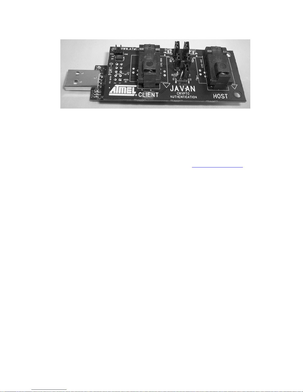
Figure 1. AT88CK109STK3 Kit
1.2.1 Device Support
AT88CK109BK3 (daughter board) currently supports the following CryptoAuthentication devices:
ATSA88100
ATSA88102
ATSA8810HS
Locate the latest information about Crypto Authentication at www.atmel.com/Javan
.
Page 6

AT88SCK109STK3
2.1 Unpacking the System
Package content:
AT88Microbase Controller
AT88CK109BK3, CryptoAuthentication daughter board
Atmel CryptoAuthentication product assortment
1 USB cable, 6 inches
2.2 System Requirements
Section 2
Getting Started
The minimum hardware and software requirements are:
200 MB free hard disk space (AVR Studio, FLIP and ATMEL’s Crypto Evaluation Studio)
Windows
®
XP, X86 processor
Available USB Port
2.3 Software Installation
Install CryptoAuthentication Demonstration Utility available from WWW.Atmel.com/Javan
Launch software and follow the online help.
Note: The CryptoAuthentication IC’s that are included with your kit have Development Secrets,
not Production secrets. See the .xml file that is included with the CryptoAuthentication
utility. Please be aware of this during your development.
2-4 AT88CK109STK3 User Guide
8699A—CRYPTO—10/09
Page 7
(
)
This chapter describes the features of the AT88Microbase and the AT88CK109BK3 boards.
3.1 Overview
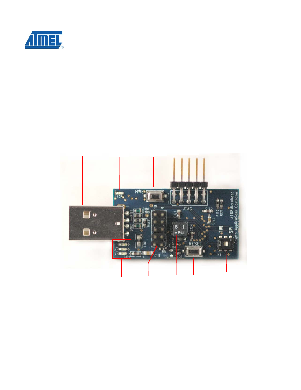
Figure 2. AT88Microbase Components (front side)
USB Type-A
PWR
LED
Hardware
Boot
HWB
Section 3
Using the AT88CK109STK3
JTAG
LED
Bank
10-Pin
Interface
Header
(J1)
Buzzer
Reset
TWI / SPI
Selector
switch
Page 8
AT88SCK109STK3
y
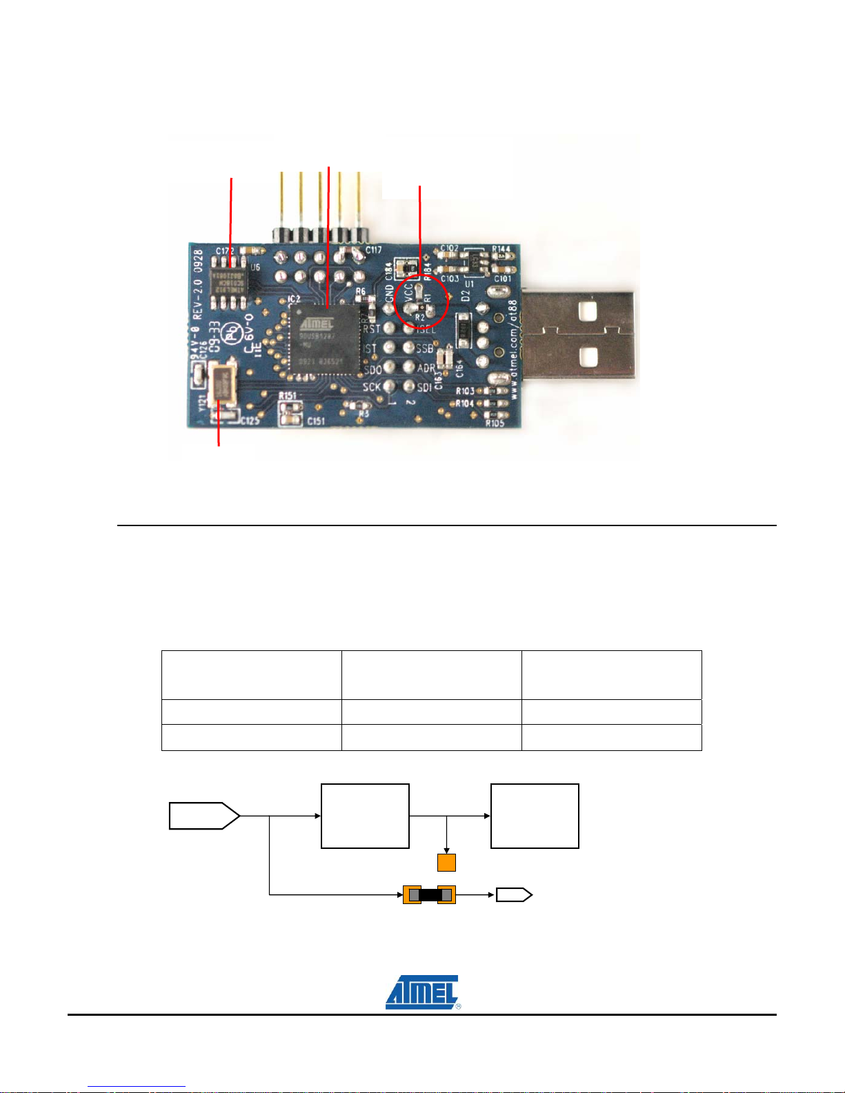
Figure 3. AT88Microbase Components (back side)
AT88SC108
CryptoCompanion
16MHz
Cr
stal
3.2 Power Supply
AT90USB1287
AVR
Main board
Supply Voltage
*see section 3.2.1
3.2.1 USB powered
The on-board power supply circuitry allows two possible configurations for the main supply voltage.
Mounted Resistor
5.0 ( USB )
The CryptoCompanion supply voltage is always 3.3V, regardless of R1and R2 configuration.
Main Board
Comments
Supply Voltage
R1 3.3V
R2 5.0V ( USB ) Default Setting
3.3V
Regulator
3.3V
R1
0 VCC
R2
* Default
CryptoCompanion
Main board
Supply Voltage
3-6 AT88CK109STK3 User Guide
8699A—CRYPTO—10/09
Page 9
Note 1: For the AT88SA100, AT88SA102, and the AT88SA10HS devices, 5.0V is
Note 2: The AT88Microbase is shipped with a 16MHz crystal, which allows the
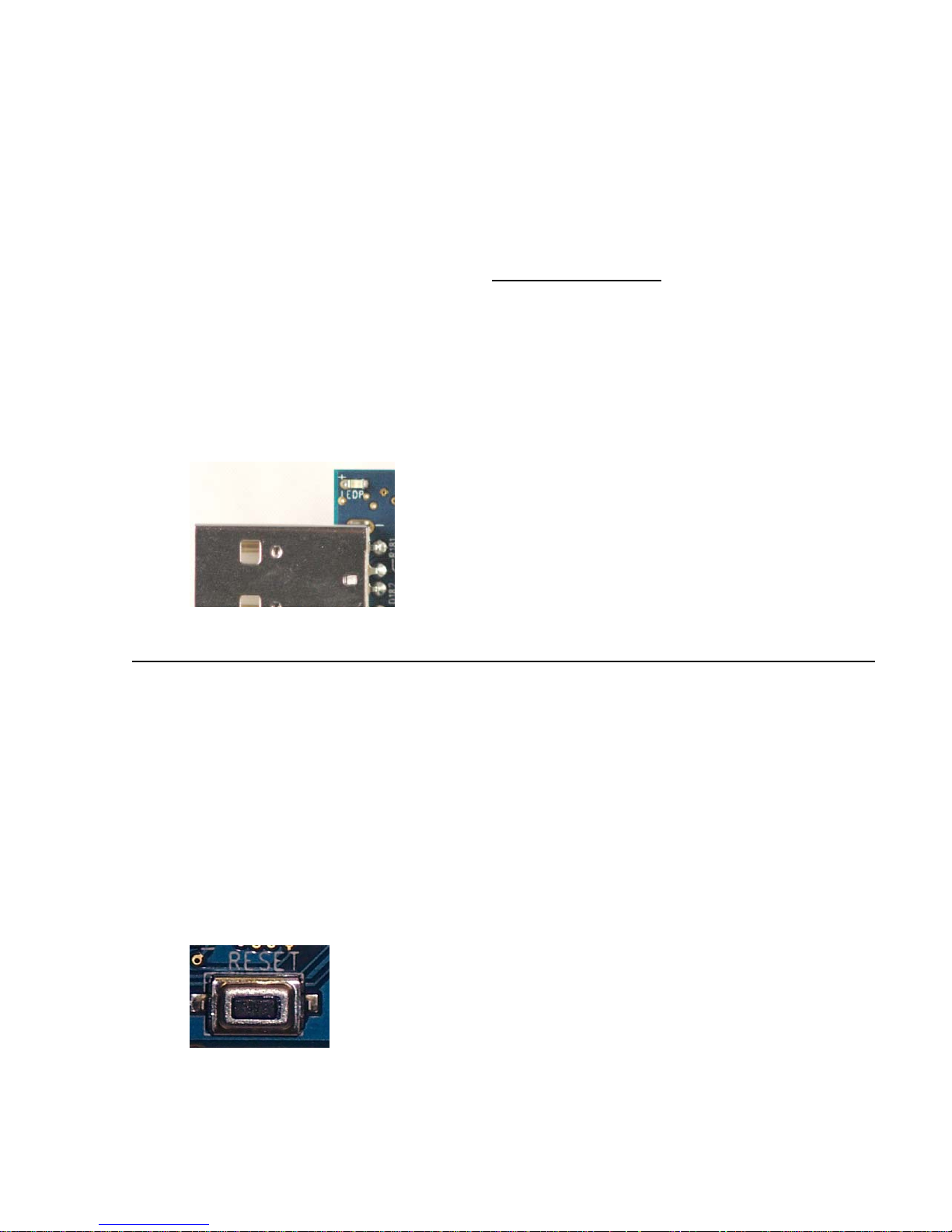
3.2.2 Power LED, “LEDP”
The blue LED (LEDP) is always lit when power is applied to the AT88Microbase regardless of the
voltage supply.
Figure 4. Power on LED “LEDP”
required to burn the fuses.
AT90USB1287 on-chip USART to obtain the 230.4K baud rate (-3.5%
error) required to communicate with a CryptoAuthentication device. The
16MHz crystal requires that
AT88Microbase below 4.5V, the 16MHz crystal must be replaced with an
8MHz crystal. The ABM3B-8.000MHZ-B2-T
replacement.
5.5VCC5.4
. To operate the
8MHz crystal is a drop-in
3.3 RESET
Although the AT90USB1287 has its on-chip RESET circuitry, (c.f. AT90USB1287 Datasheet,
section “System Control and Reset”), the AT88Microbase provides two additional means to reset
the AT90USB1287.
3.3.1 Power-on Reset
The on-board RC network acts as power-on RESET.
3.3.2 RESET Push Button
By pressing the RESET push button on the AT88Microbase, a warm RESET of the AT90USB1287
AVR is performed.
Figure 5. RESET Push Button (AVR RESET) Implementation
Page 10
AT88SCK109STK3
3.4 AT90USB1287 AVR Microcontroller
To use the USB interface of the AT90USB1287, the clock source should always be a crystal or an
external clock oscillator (the internal 8MHz RC oscillator cannot be used to operate the USB
interface). Only the following crystal frequencies allow proper USB operations: 2MHz, 4MHz,
6MHz, 8MHz, 12MHz, and 16MHz. The AT88Microbase comes with a default 16MHz crystal
oscillator, which is required to obtain the 230.4K USART baud rate needed for
CryptoAuthentication communication.
3.5 Serial Links
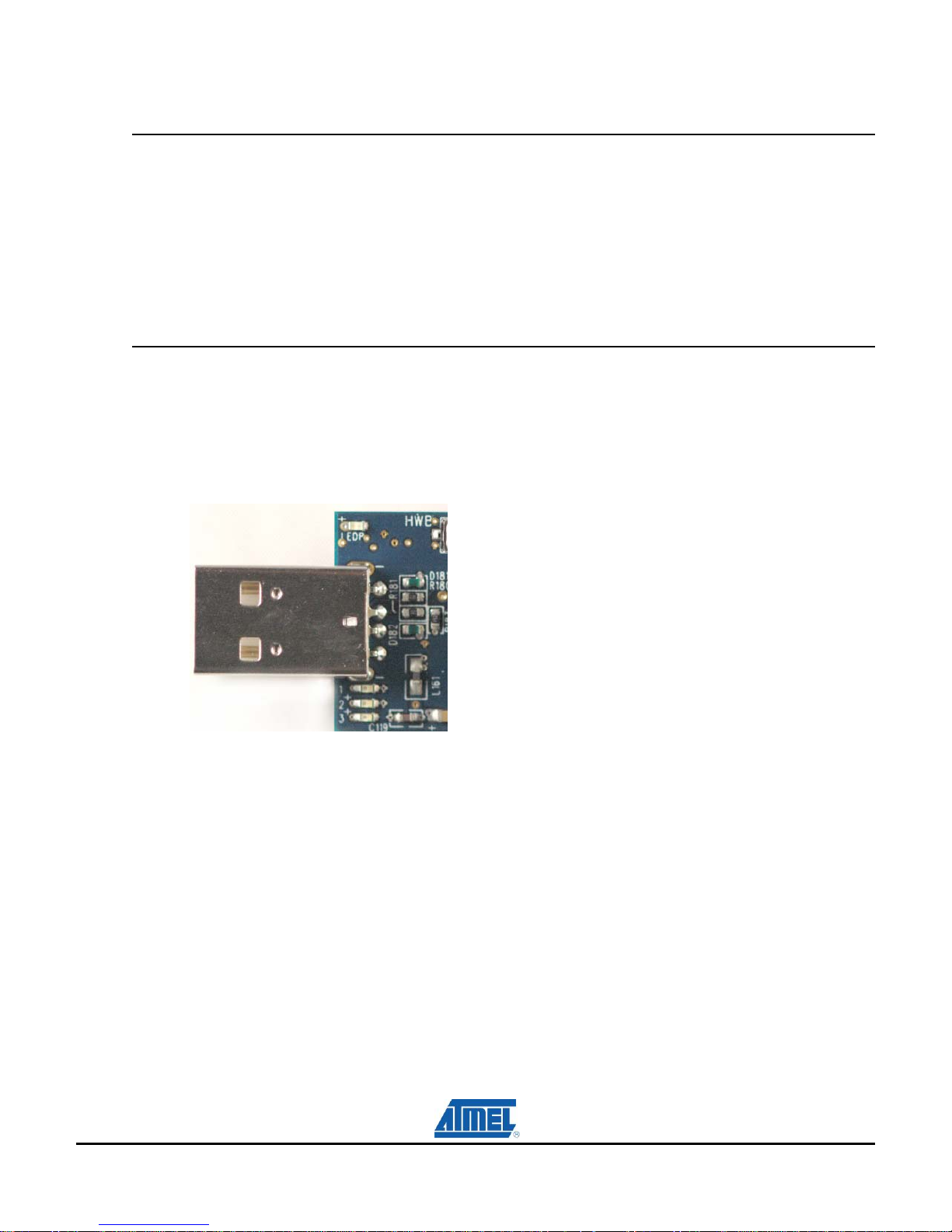
3.5.1 USB
The AT88Microbase is supplied with a standard USB Type-A receptacle. The AT88Microbase only
operates as an “USB device”.
Figure 6. USB Type-A Receptacle
3.5.2 USART
The AT90USB1287 AVR comes with an on-chip USART peripheral (USART1). Only the
asynchronous mode is supported. See section 3.6.3 for pinout details.
3.5.3 SPI / TWI Selector Switch
The SPI – TWI selector switch (K1) allows either the SPI pins (MOSI and SCLK) or the TWI pins
(SDA and SCL) to be routed to the 10 pin Interface header, J1. See section 3.6.3 for pinout details.
Figure 7. TWI – SPI Selector Switch
3-8 AT88CK109STK3 User Guide
8699A—CRYPTO—10/09
Page 11
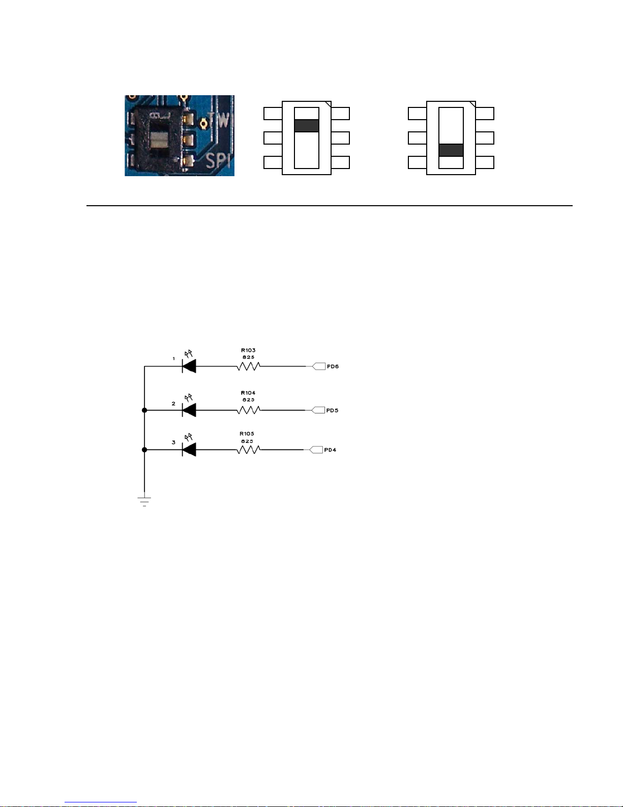
3.6 On-board Resources
3.6.1 Description of LED Bank
The AT88Microbase includes 3 general purpose red LEDs, which are connected to PD6, PD5 and
PD4. To light an LED, the corresponding port pin must be driven high. To turn off an LED, the
corresponding port pin must be driven low.
Figure 8. LEDs Implementation Schematic
K1
TWI Position
TWI
SPI
K1
SPI Position
TWI
SPI
Note: AVR can source or sink enough current to drive an LED directly.
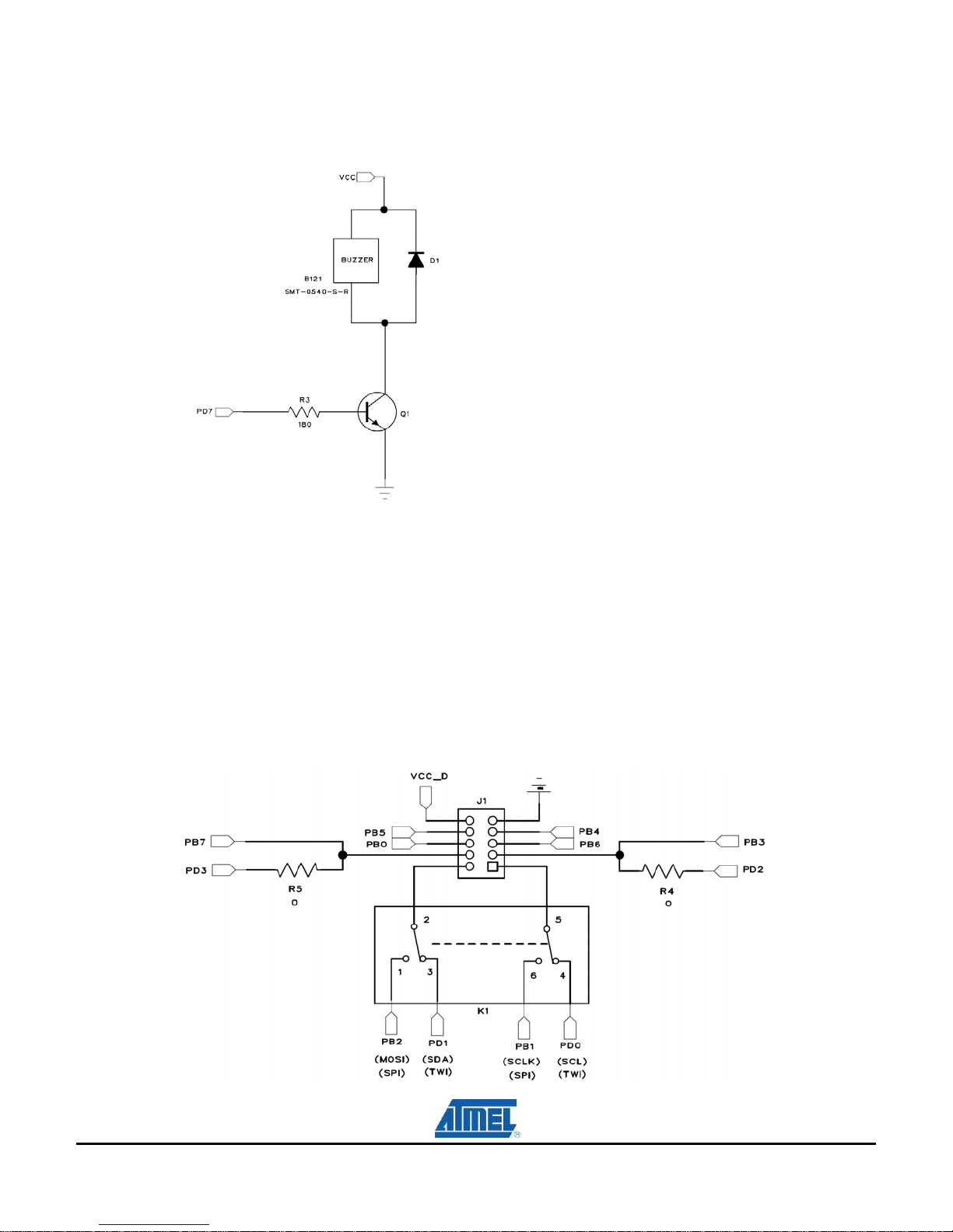
3.6.2 Buzzer
The small onboard buzzer adds audio capability to the AT88Microbase board. The buzzer requires
that PD7 be driven with a square wave at
4.0 0.5
KHz to achieve a maximum decibel of 78dB.
Page 12
AT88SCK109STK3
Figure 9. Buzzer Implementation Schematic
Brief Spec:
Input Signal: Square Wave
Resonant frequency:
Sound Pressure Level: 78dB
3.6.3 Description of the Interface Header
The 10-Pin header (J1) of the AT88Microbase provides interfacing for daughter boards.
Figure 10. 10-Pin Interface Header
4.0 0.5
KHz
3-10 AT88CK109STK3 User Guide
8699A—CRYPTO—10/09
Page 13

Figure 11. 10-Pin Interface header (J1) Orientation
USB
3.6.4 CryptoCompanion Chip
The AT88Microbase has one CryptoCompanion device (AT88SC108), which is located on the back
side of board. The AT88SC018 is designed as the mate to Atmel’s CryptoRF® (CRF) and
CryptoMemory® (CM) chips. The SCL and SDA pins are connected to PD0 and PD1, respectively.
The RST and PDN pins are connected to PF2 and PF3, respectively.
Figure 12. System CryptoCompanion Schematic
HWB
VCC_D
PB5
PB0
PB7 / PD3
PB2/ PD1
J1
GND
PB4
PB6
PB3 / PD2
PB1/
PD0
JTAG
RESET
SPI
TWI
Datasheet can be found on the Atmel web site, http://www.atmel.com/products/securemem.
Note: The CryptoCompanion chip cannot be used with the CryptoAuthentication family of devices.
Page 14

AT88SCK109STK3
The following sections 3.7 – 3.11 describe the AT88CK109BK3 CryptoAuthentication
daughter board.
3.7 AT88CK109BK3 CryptoAuthentication Daughter Board
Figure 13. AT88CK109BK3 Components (top side)
CLIENT
PWR LED
HOST
PWR LED
SOT23-3
Socket
10-Pin
Interface Header
INTERCONNECT
Header
AT88CK109BK3 has two SOT23-3 sockets that support the AT88SA100, AT88SA102, and the
AT88SA10HS 3-leads devices.
Figure 14. Chip-in-Socket Placement (Live bug)
3.8 AT88CK109BK3 HOST and CLIENT Sockets Compatibility
AT88CK109BK3 is supplied with two SOT23-3 sockets titled HOST and CLIENT. Since both
sockets have identical pinout’s, the AT88Microbase can physically accept a host or a client device
in either socket. Therefore, the AT88CK109BK3 can be configured for either a host-client or clientclient development.
3-12 AT88CK109STK3 User Guide
8699A—CRYPTO—10/09
Page 15

Note: When using the demonstration software, the host (AT88SA10HS) and client (AT88SA100 or
AT88SA102) devices must be in their respective sockets according to the “HOST” and “CLIENT”
texts on the board.
3.9 HOST and CLIENT Power Configuration
The AT88CK109BK3 provides the user with the capability to independently power cycle each
socket with software or place the sockets in a constant power-on state, assuming power is applied
to the board.
Figure 15. HOST and CLIENT Power Headers
Figure 16. Schematic Implementation for Software Power Control, HOST-side
Table 1.
HOST and CLIENT sockets Power Configuration
Jumpers Position Comments View
Hardware Power
Configuration
H1, H2, H3 and H4
Mounted
With all 4 jumpers mounted, the HOST and CLIENT
sockets are placed into a constant power–on state.
*Default setting
H4 H3
H2 H1
Page 16

AT88SCK109STK3
HOST
Software Power
Configuration
This configuration allows the user to power cycle the
HOST socket via software. See Table 2 and 3 for
H1 Mounted
H2 Not - mounted
CLIENT
Software Power
Configuration
H3 Mounted
This configuration allows the user to power cycle the
CLIENT socket via software. See Table 2 and 3 for
H4 Not - mounted
3.10 Device Interconnect Header
The “INTERCONNECT” header provides a single-wire bus between the signal pins of the HOST
and CLIENT devices. The header can also serve as test points.
pinout details
pinout details
H2 H1
H4 H3
Figure 17. Interconnect Header
CLEINT HOST
SIGNAL SIGNAL
Px3 Px4
Maps to
AT88Microbase PB7
INTERCONNECT
AT88Microbase PB6
3.11 Mapping AT88CK109BK3 to AT88Microbase, STK500 and STK600
The AT88CK109BK3 maps to the 10-pin header of the AT88Microbase as follow:
Table 2.
AT88Microbase
Header ( J1 )
Mapping the AT88CK109BK3 to the AT88Microbase
AT88CK109BK3 Comments
PB0 Software Power Control HOST Socket
Maps to
3-14 AT88CK109STK3 User Guide
8699A—CRYPTO—10/09
Page 17

PB1 NC Not Connected
PB2 NC
PB3 Tied to PB7 with R11 USART (Receive)1
PB4 Software Power Control CLIENT Socket
PB5 NC
PB6 HOST Signal Pin Bit-banging
PB7 CLIENT Signal Pin Bit-banging / USART (Transmit )1
GND GND GND
VCC VCC VCC
Table 3. Mapping AT88CK109BK3 to the STK500 and STK600
STK500 / STK600 AT88CK109BK3 Comments
Px0 NC -
Px1 NC -
Px2 Tied to Px3 with R111 USART (Receive)1
Px3 CLIENT Signal Pin Bit-banging / USART (Transmit )1
Px4 HOST Signal Pin Bit-banging
Px5 Software Power Control HOST Socket
Px6 Software Power Control CLIENT Socket
Px7 NC -
GND GND GND
VTG VCC VCC
Figure 18. AT88CK109BK3 Mounted to the STK500
1
See section 3.12
Note 3: “x” in Table 3 denotes any port on the STK500 and STK600
Page 18

AT88SCK109STK3
3.12 Interfacing a USART with CryptoAuthentication
A microcontroller’s USART requires a minimum of two signals (RXD and TXD) to communicate.
The AT88SA100, AT88SA102, and AT88SA10HS devices have a 1-wire communication interface.
The make the USART compatible with a 1-wire CryptoAuthentication device, the USART’s pins (TX
and Rx) are tied together.
Figure 19. USART TXD and RXD pins configured for 1-wire Interfacing
On the AT88CK109BK3, Px2 and Px3 are tied together with a zero ohm resistor (R11). When
mounted to the AT88Microbase, pins Px2 and Px3 align with pins (PB3/PD2) and (PB7/PD3). The
USART pins, PD2 (RXD) and PD3 (TXD), are effectively tied together with R11allowing the USART
to be compatible with the CryptoAuthentication 1-wire interface.
3.13 In-System Programming
3.13.1 Programming with USB bootloader: DFU (Device Firmware Upgrade)
AT90USB1287 AVR comes with a default factory pre-programmed USB bootloader located in the
on-chip boot section of the AT90USB1287. This is the easiest and fastest way to reprogram the
device directly over the USB interface. The “Flip” PC side application, available for free on Atmel
website, offers a flexible and user friendly interface for reprogramming the application over the USB
bus.
The “HWB” push button is used to place the AVR into DFU mode after reset (Refer to
AT90USB1287 datasheet section “boot loader support”).
The following steps enable the DFU mode:
1. Press and hold “HWB” button
2. Press the “RESET” button
3. Release the “RESETT” button.
4. Release the “HWB” button.
For more information about the USB bootloader and FLIP software, please refer to the ‘USB
bootloader datasheet’ document and ‘FLIP User Manual’.
Note: HWBE fuse must be enabled to support DFU.
3-16 AT88CK109STK3 User Guide
8699A—CRYPTO—10/09
Page 19

3.13.2 Programming with AVR JTAG ICE
The AT90USB1287 can be programmed using specific the JTAG link. This sub-section will explain
how to connect and use the AVR JTAG ICE.
Note: When the JTAGEN fuse is disabled, the four TAP pins are normal port pins, and the TAP
controller is in reset. When the JTAGEN fuse is enabled, the input TAP signals are
internally pulled high. This enables the JTAG for Boundary-scan and programming. The
AT90USB1287 device is shipped with this fuse programmed.
Figure 20. Connecting AVR JTAGICE mkII to the AT88Microbase
The Flash, EEPROM and all Fuse and Lock Bit options ISP-programmable, can be programmed
individually or with the sequential automatic programming option.
Note: See AVR Studio® on-line Help for information.
3.14 Debugging
3.14.1 Debugging with AVR JTAG ICE mkII
Every AT88CK109STK3 can be used for debugging with JTAG ICE MK II.
Connect the JTAG ICE mkII as shown in Figure 20, for debugging help; please refer to AVR
Studio® Help information.
Page 20

AT88SCK109STK3
When using JTAG ICE MK II for debugging, and as AT90USB1287 parts are factory configured
with the higher security level set, a chip erase operation will be performed on the part before
debugging. Thus the on-chip flash bootloader will be erased. It can be restored after the debug
session using the bootloader hex file available from ATMEL website.
3.15 Test Points
There are 4 test points implemented, these test points are referenced in the full schematics section.
VCC, AT88CK109BK3
GND AT88CK109BK3
HOST signal pin AT88CK109BK3 INTERCONNECT Header
CLIENT signal pin AT88CK109BK3 INTERCONNECT Header
3-18 AT88CK109STK3 User Guide
8699A—CRYPTO—10/09
Page 21

Section 4
Troubleshooting Guide
Table 4. Troubleshooting Guide
Problem Reason Solution
The blue Power LED is not on. USB Port of AT88Microbase is not
connected to PC.
The AVR device cannot be
programmed.
AVR Studio does not detect
JTAG or ISP programmer.
FLIP program not working. AT88Microbase is not in DFU mode. JTAG to load the bootloader and set
The JTAG header is not connected
to JTAG programmer.
The memory lock bits are
programmed.
Reset disable fuse is set. Check reset disable fuse.
Programming too fast with ISP SPI Check oscillator settings and make
USB Port of AT88Microbase is not
connected to PC (programmed
through USB).
AT88Microbase is not in DFU mode.
The communication medium in FLIP
hasn't been selected
JTAG or ISP programmer is not
connected or power is off.
Connect AT88Microbase USB port
to PC's USB port.
Connect the JTAG header to the
JTAG programmer.
Erase the memory before
programmed.
sure it is not set higher than SPI
clock
Connect AT88Microbase USB port
to PC's USB port.
― Press and hold the “HWB” push
button.
― Press the “RESET” push button.
― Release the “RESET” push
button.
― Release the “HWB” push button.
From the FLIP menu, select
“Settings > Communication > USB”.
Connect JTAG programmer to
JTAG header or ISP programmer to
ISP header and check power
connections.
(check) the HWBE fuse.
Correct fuse settings:
Reading fuses address 0 to 2..
0xDE, 0x99, 0xF3
AT88CK109STK User Guide 4-1
8699A—CRYPTO—10/09
Page 22

Section 5
Technical Specifications
System Unit
― AT88Microbase
o Physical Dimensions L=58 x W=25 x H=12 mm
o Weight 9.0g
― AT88CK109BK3
o Physical Dimensions L=74 x W=35 x H=23 mm
o Weight 17.5g
― Assembled Module
o Physical Dimensions L=100 x W=35 x H=26 mm
o Weight 26.5g
Operating Conditions
― USB 4.4V - 5V.25 (100mA)
*See Section 3.2 3.3V
― Supply Current 50mA
Connections
― USB Connector Type-A receptacle
― USB Communications Full speed 2.0
AT88CK109STK User Guide 5-1
8699A—CRYPTO—10/09
Page 23

Section 6
Technical Support
For technical support, please contact securerf@atmel.com. When emailing or contacting tech
support, please do not include any proprietary information you may have input into the device.
When requesting technical support, please include the following information:
Which target AVR device is used (complete part number)
Target voltage and speed
Clock source and fuse setting of the AVR
Programming method (ISP, JTAG or specific Boot-Loader)
Hardware revisions of the AVR tools, found on the PCB
Version number of AVR Studio. This can be found in the AVR Studio help menu.
PC operating system and version/build
PC processor type and speed
A detailed description of the problem
AT88CK109STK User Guide 6-1
8699A—CRYPTO—10/09
Page 24

Section 7
Complete Schematic
On the next pages, the following documents of the AT88CK109STK3 are shown:
AT88Microbase, revision 2.0
Complete Schematic
Assembly Drawing
Bill of Material
Default configuration summary
AT88CK109BK3, revision 1.0
Complete Schematic
Assembly Drawing
Bill of Material
Default configuration summary
8699A—CRYPTO—10/09
Page 25

AT88CK109STK3
Figure 1. AT88Microbase Schematic, 1 of 4
7-2 AT88CK109STK3 User Guide
8699A—CRYPTO—10/09
Page 26

Figure 2. AT88Microbase Schematic, 2 of 4
Page 27

AT88CK109STK3
Figure 3. AT88Microbase Schematic, 3 of 4
7-4 AT88CK109STK3 User Guide
8699A—CRYPTO—10/09
Page 28

Figure 4. AT88Microbase Schematic, 4 of 4
Page 29

AT88CK109STK3
Figure 5. AT88Microbase Assembly Drawing, 1 of 2 ( Top side )
7-6 AT88CK109STK3 User Guide
8699A—CRYPTO—10/09
Page 30

Figure 6. AT88Microbase Assembly Drawing, 2 of 2 ( Bottom side )
Page 31

AT88Microbase BOM
Qty Reference Value Description Case Manufacturer PN
CAPACITOR
2 C125-126 20pF Ceramic 0603 GRM1885C1H200JA01D
1 C164 150pF Ceramic 0603 C1608C0G1H151J
1 C151 1nF Ceramic 0603 C0603X7R500-102KNE
1 C102 10nF Ceramic 0603 C0603X7R500-103JNE
1 C163 15nF Ceramic 0603 ECJ1VB1H153K
1 C184 220nF Ceramic 0603 GRM188R71A224KA01D
5 C117 C119 0.1uF Ceramic 0603 C0603Y5V250-104ZNE
C121 Ceramic 0603
C123-124 Ceramic 0603
4 C101 C103 1uF Ceramic 0603 C0603Y5V250-105ZNE
C120 C172 Ceramic 0603
1 C118 10uF Ceramic 0805 C0805X5R6R3-106KNE
RESISTOR
1 R1 0 1/16 W 0603 CR0603-16W-000T
2 R180-181 22 1/16 W 0603 CR0603-16W-220JT
3 R3 R6-R7 180 1/16 W 0603 CR0603-16W-181JT
4 R103-105, R171 825 1/16 W 0603 CRCW0603825RFKEA
1 R183 1.5K 1/16 W 0603 CR0603-16W-152JT
1 R144 4.7K 1/16 W 0603 CR0603-16W-472JT
1 R172 3.92K 1/16 W 0603 ERJ3EKF3921V
2 R151 R184 47K 1/16 W 0603
1 R2 DNI 1/16 W 0603
2 R4, R5 0 1/16 W 0402
CRCW060347K0FKEA
CR0402-16W-000T
IC
1 IC2 - ATMEL AVR 64 PIN QFN AT90USB1287-64QFN
1 Y121 16MHz Crystal SMD ABM3B-16.000MHZ-B2-T
1 U1 3.3V Regulator SOT-23-5 MIC5219-3.3YM5 TR
1 U6 - ATMEL CryptoCompanion 8ld SOIC ATSC018-SU-CM
DIODE
1 LEDP BLUE LED 0603 MB1111C-TR
3 LED1-3 RED LED 0603 BR1111C-TR
2 D181-182 - ESD Suppressor 0603 PGB1010603MR
1 D1 DIODE Schotkky SOD-323 NSR1020MW2T1G
1 D2 DIODE Schotkky SOD-123 MBR0520L
MISC
1 USB WM17117-ND TYPE A USB RT ANG.
1 L161 - Ferrit Bead 0603 MI0603J601R-10
1 Q1 NPN Transistor SOT23-3 MMBTA42LT1G
1 H2 0.1" Pitch JTAG 2x5 Male Header RA TSW-105-16-L-D-RA
1 J1 0.1" Pitch PORT-D Interface 2x5 Male Header PBC05DAAN
1 B121 - Buzzer SMD SMT-0540-S-R
2 B151 - Push Button SMD PTS635SL25SMTR LFS
1 K1 - DPDT switch SMD CAS-220TA
48037-0001
7-8 AT88CK109STK3 User Guide
8699A—CRYPTO—10/09
Page 32

Figure 7. AT88CK109BK3 Schematic, 1 of 3
Page 33

AT88CK109STK3
Figure 8. AT88CK109BK3 Schematic, 2 of 3
7-10 AT88CK109STK3 User Guide
8699A—CRYPTO—10/09
Page 34

Figure 9. AT88CK109BK3 Schematic, 3 of 3
Page 35

AT88CK109STK3
AT88CK109BK3 Assembly Drawing, 1 of 2 ( Top side )
7-12 AT88CK109STK3 User Guide
8699A—CRYPTO—10/09
Page 36

Figure 10. AT88CK109BK3 Assembly Drawing, 2 of 2 ( Bottom side )
Page 37

AT88CK109STK3
AT88CK109BK3 BOM
ty Reference Value Description Case Manufacturer PN
2 C1-2 0.1uF 402 C0402X7R160-104KNE
CAPACITOR
1 R11 0 1/16W 0603 CR0603-16W-000T
2 R9-10 180 1/16W 0603 CR0603-16W-181JT
4 R1-3, R5 1K 1/16W 0603 CR0603-16W-1001FT
2 R7-8 1M 1/16W 0603 CR0603-16W-105JT
2 R4 R6 825 1/16W 0603 CRCW0603825RFKEA
RESISTOR
DIODE
2 LED1-2 RED LED 0603 BR1111C-TR
2 Q1-2 N-CHANNEL MOSFET SC-75 NTA4001NT1G
1 D1 Diode Unidirectional TVS DO-214AC, SMA SMA6J5.0A-TR
2 S1-2 CryptoAuthentication Socket SOT23-3 499-P36-20
6
Interconnect
1 PORT-D 10 Pin 2x5 VERT .100 10POS Fem SSW-105-01-G-D
2 K1-2 Switch DPDT Surface Mount CAS-220TA
H1-5,
MISC
PBC02DAAN2POS .100 TINVERT 2PIN HEADER
7-14 AT88CK109STK3 User Guide
8699A—CRYPTO—10/09
Page 38

Headquarters
Atmel Corporation
2325 Orchard Parkway
San Jose, CA 95131
USA
Tel: 1(408) 441-0311
Fax: 1(408) 487-2600
International
Atmel Asia
Room 1219
Chinachem Golden Plaza
77 Mody Road Tsimshatsui
East Kowloon
Hong Kong
Tel: (852) 2721-9778
Fax: (852) 2722-1369
Atmel Europe
Le Krebs
8, Rue Jean-Pierre Timbaud
BP 309
78054 Saint-Quentin-enYvelines Cedex
France
Tel: (33) 1-30-60-70-00
Atmel Japan
9F, Tonetsu Shinkawa Bldg.
1-24-8 Shinkawa
Chuo-ku, Tokyo 104-0033
Japan
Tel: (81) 3-3523-3551
Fax: (81) 3-3523-7581
Fax: (33) 1-30-60-71-11
Product Contact
Web Site
www.atmel.com
Literature Requests
Technical Support
secureRF@atmel.com
Sales Contact
www.atmel.com/contacts
www.atmel.com/literature
Disclaimer: The information in this document is provided in connection with Atmel products. No license, express or implied, by estoppel or otherwise, to any
intellectual property right is granted by this document or in connection with the sale of Atmel products. EXCEPT AS SET FORTH IN ATMEL’S TERMS AND
CONDITIONS OF SALE LOCATED ON ATMEL’S WEB SITE, ATMEL ASSUMES NO LIABILITY WHATSOEVER AND DISCLAIMS ANY EXPRESS, IMPLIED OR
STATUTORY WARRANTY RELATING TO ITS PRODUCTS INCLUDING, BUT NOT LIMITED TO, THE IMPLIED WARRANTY OF MERCHANTABILITY, FITNESS
FOR A PARTICULAR PURPOSE, OR NON-INFRINGEMENT. IN NO EVENT SHALL ATMEL BE LIABLE FOR ANY DIRECT, INDIRECT, CONSEQUENTIAL,
PUNITIVE, SPECIAL OR INCIDEN-TAL DAMAGES (INCLUDING, WITHOUT LIMITATION, DAMAGES FOR LOSS OF PROFITS, BUSINESS INTERRUPTION,
OR LOSS OF INFORMATION) ARISING OUT OF THE USE OR INABILITY TO USE THIS DOCUMENT, EVEN IF ATMEL HAS BEEN ADVISED OF THE
POSSIBILITY OF SUCH DAMAGES. Atmel makes no representations or warranties with respect to the accuracy or completeness of the contents of this document
and reserves the right to make changes to specifications and product descriptions at any time without notice. Atmel does not make any commitment to update the
information contained herein. Unless specifically provided otherwise, Atmel products are not suitable for, and shall not be used in, automotive applications. Atmel’s
products are not intended, authorized, or warranted for use as components in applications intended to support or sustain life.
© 2009 Atmel Corporation. All rights reserved. Atmel®, Atmel logo and combinations thereof, AVR®, AVR Studio®, CryptoMemory® and others, are registered
trademarks or trademarks of Atmel Corporation or its subsidiaries. Windows® and others are registered trademarks or trademarks of Microsoft Corporation. Other
terms and product names may be trademarks of others.
8699A—CRYPTO—10/09
 Loading...