

Atmel AT7910E Datasheet

7796G AERO 02/13
AT7910E
SpW-10X SpaceWire Router
DATASHEET
Features
SpaceWire Router
Logical to Physical addressing translation
Priority Management
Header Deletion Capability
Eight Bidirectional SpaceWire links
Full duplex communication
Data rate from 2 up to 200 Mbit/s in each direction
Two External Interfaces
Dedicated Input and Output FIFOs
9-bit wide Interface
Configuration Port
Read/Write Accesses to internal registers
Accessible from both the spacewire links (8 channels) and the external interfaces
Remote Memory Access Protocol (RMAP) support
Time Code Interface
Master/Slave Capability
Error/Status Interface
Operating range
Voltages 3V to 3.6V
Temperature - 55°C to +125°C
Maximum Power consumption
All spacewire links active at 200Mbit/s : 4W
Radiation Performance
Total dose tested successfully up to 300 Krad (Si)
No single event latchup below a LET of 80 MeV/mg/cm2
ESD better than 2000V
Quality Grades
QML-Q or V with SMD
Package: 196pins MQFPF
Mass: 12grams

2
Description
The SpW-10X SpaceWire routing switch is capable of connecting many nodes, providing
a means of routing packets between the nodes connected to it. It comprises eight
SpaceWire link interfaces and a routing matrix. The routing matrix enables packets
arriving at one link interface to be transferred to and sent out of another link interface on
the routing switch.
The AT7910E was designed by Austrian Aerospace (Austria) and the University of
Dundee (Scotland). It is manufactured using the SEU hardened cell library from Atmel
MH1RT CMOS 0.35µm radiation hardened sea of gates technology.
For any technical question relative to the functionality of the AT7910E please contact
Atmel technical support at assp-applab.hotline@nto.atmel.com.
This document must be read in conjunction with the University of Dundee “SpaceWire
Router SpW-10X User Manual” available at www.atmel.com.
AT7910E [DATASHEET]
7796G AERO 02/13

3
Table of Contents
1. Functional Description ........................................................................ 4
1.1 SpaceWire Ports ............................................................................................... 5
1.2 External Ports.................................................................................................... 5
1.3 Configuration Port ............................................................................................. 5
1.4 Routing table ..................................................................................................... 5
1.5 Routing control logic and crossbar .................................................................... 6
1.6 Time Code Processing ...................................................................................... 6
1.7 Control/Status Registers ................................................................................... 6
2. Typical Applications ........................................................................... 7
2.1 Stand-alone router ............................................................................................ 7
2.2 Node interface ................................................................................................... 7
2.3 Embedded router .............................................................................................. 8
3. PLL Filter ........................................................................................... 9
4. LVDS Interface ................................................................................. 10
4.2 AT7910E Limitation ......................................................................................... 10
4.3 AT7910E Compatibility with LVDS receiver Standards ................................... 11
5. Package Information ........................................................................ 12
5.1 Package Outline .............................................................................................. 12
5.1.1 MQFPF 196 ...................................................................................... 12
5.2 Pin Description ................................................................................................ 14
5.3 Electrical Characteristics ................................................................................. 16
5.4 Absolute Maximum Ratings ............................................................................ 16
5.5 DC Electrical Characteristics ........................................................................... 16
5.6 Power consumption ......................................................................................... 16
5.7 AC Electrical Characteristics ........................................................................... 17
6. Ordering Information ........................................................................ 19
6.1 AT7910E Ordering Codes ............................................................................... 19
7. Revision History ............................................................................... 20
AT7910E [DATASHEET]
7796G AERO 02/13
4
1. Functional Description
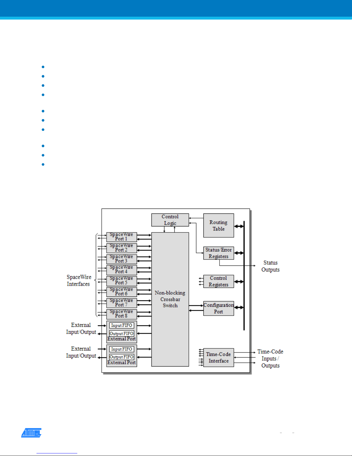
The SpaceWire router comprises the following functional logic blocks:
Eight SpaceWire bi-directional serial ports.
Two external parallel input/output ports each comprising an input FIFO and an output FIFO.
A non-blocking crossbar switch connecting any input port to any output port.
An internal configuration port accessible via the crossbar switch from the external parallel input/output port or the
SpaceWire input/output ports.
A routing table accessible via the configuration port which holds the logical address to output port mapping.
Control logic to control the operation of the switch, performing arbitration and group adaptive routing.
Control registers than can be written and read by the configuration port and which hold control information e.g. link
operating speed.
An external time-code interface comprising tick_in, tick_out and current tick count value
Internal status/error registers accessible via the configuration port
External status/error signals
A block diagram of the routing switch is given in the following figure:
Figure 1. SpaceWire Router Block Diagram
AT7910E [DATASHEET]
7796G AERO 02/13

5
The AT7910E provides a routing capability between eight SpaceWire links according to the SpaceWire Standard ECSSE-50-12A. In addition for use as a node interface, the AT7910E integrates other interfaces such as:
External ports
Configuration port
Time-code interface
Control/Status interface
1.1 SpaceWire Ports
The SpaceWire router has eight bi-directional SpaceWire links each compliant with the SpaceWire standard ECSS-E-5012A.
Each SpaceWire link is controlled by an associated link register and routing control logic. Packets received on SpaceWire
links are routed by the routing control logic to the configuration port, other SpaceWire link ports or the external FIFO ports
depending on the packet address.
Packets with invalid addresses are discarded by the SpaceWire router. The SpaceWire link status is recorded in the
associated link register and error status is held by the router until cleared by a configuration command.
1.2 External Ports
The SpaceWire router has two bi-directional parallel FIFO interfaces that can be used to connect the router to an external
host system. The external port FIFO is two data characters deep.
Each FIFO is written to or read from synchronously with the 30MHz system clock.
An eight-bit data interface and an extra control bit for end of packet markers are provided by each external port FIFO.
Packets received by the external port are routed by the routing control logic to the configuration port, SpaceWire link ports
or the other external port depending on the packet address.
Packets with invalid addresses are discarded by the SpaceWire router.
1.3 Configuration Port
The SpaceWire router has one configuration port which performs read and write operations to internal router registers.
Packets are routed to the configuration port when a packet with a leading address byte equal to zero is received. The
Remote Memory Access Protocol (RMAP) is used to access the configuration port.
If an invalid command packet is received then the error is flagged to an associated status register and the packet is
discarded.
1.4 Routing table
The SpaceWire router routing table is set by the router command packets to assign logical addresses to physical
destination ports on the router.
A group of destination ports can be set, in each routing table location, to enable group adaptive routing. When a packet is
received with a logical address the routing table is checked by the routing control logic and the packet is routed to the
destination port when the port is ready. Routing table locations are set to invalid at power on or at reset.
The routing table logical addresses can also be set to support high priority and header deletion. High priority packets are
routed before low priority packets and header deletion of logical addresses can be used to support regional logical
addressing.
An invalid routing address will cause the packet to be spilled by the control logic.
AT7910E [DATASHEET]
7796G AERO 02/13

6
1.5 Routing control logic and crossbar
The routing control logic is responsible for arbitration of output ports, group adaptive routing and the crossbar switching.
Arbitration is performed when two or more source ports are requesting to use the same destination port.
A priority based arbitration scheme with two priority levels, high and low, is used where high priority packets are routed
before low priority packets. Fair arbitration is performed on packets which have the same priority levels to ensure each
packet gets equal access to the output port.
Group adaptive routing control selects one of a number of output ports for sending out the source packet.
1.6 Time Code Processing
An internal time-code register is used in the router to allow the router to be a time-code master or a time-code slave.
In master mode the time-code interface is used to provide a tick-in to the SpaceWire routing causing time-codes to be
propagated through the network. Two modes of time master operation are supported, an automatic mode where a timecode is propagated on each external tick-in and a normal mode where the time-code is propagated dependent on the
external time-in signal.
In time-code slave mode a valid received time-code, one plus the value of the router time-code register, causes a tick-out
to be sent to the SpaceWire links and the external time-code interface. The time-code is propagated to all time-code ports
except the port on which the time-code was received. If the time-code received is not one plus the value of the time-code
register then the time-code register is updated but the tick-out is not performed. In this way, circular network paths do not
cause a constant stream of time-codes to be sent in a loop.
1.7 Control/Status Registers
The control and status registers in the SpaceWire router provide the means to control the operation of the router, set the
router configuration and parameters or monitor the status of the device. The registers are accessed using RMAP
command packets received by the configuration port.
AT7910E [DATASHEET]
7796G AERO 02/13
7
2. Typical Applications
The AT7910E SpaceWire router is perfectly suited for development of applications requiring a standalone router, a
terminal node with SpaceWire interface or a mixed configuration of the two previous ones.
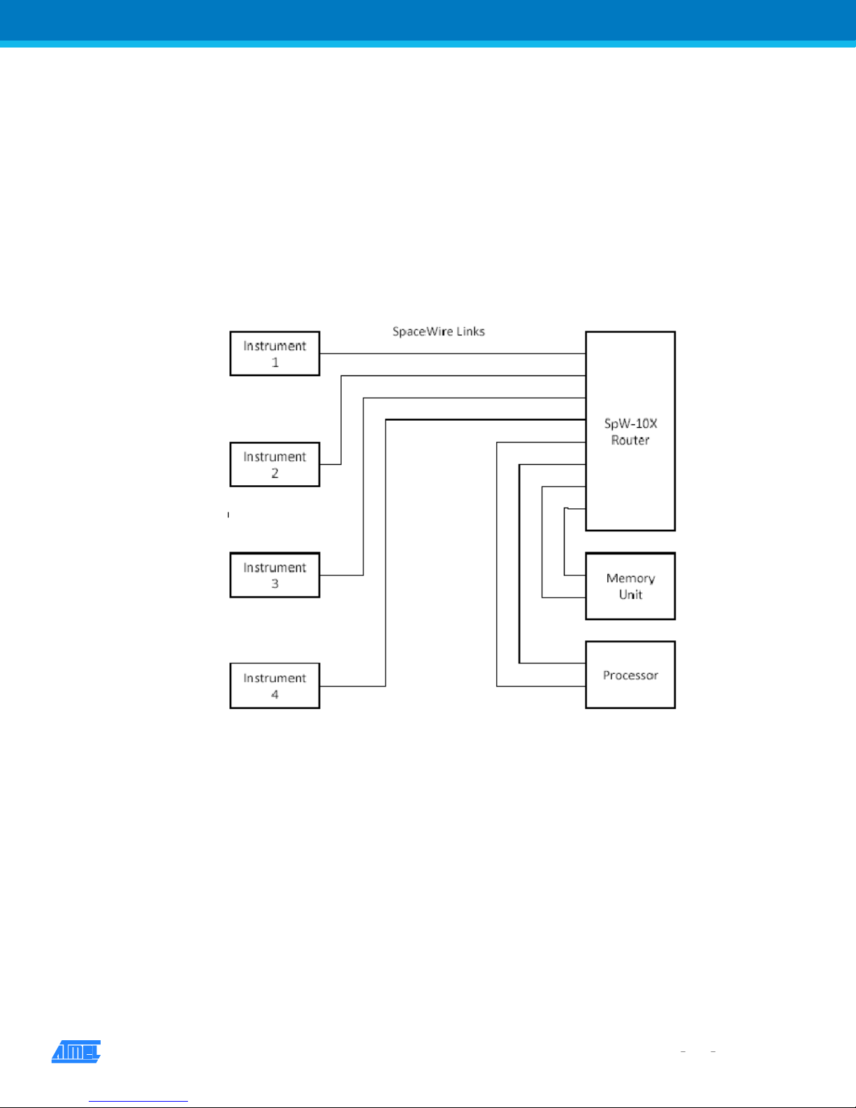
2.1 Stand-alone router
The AT7910E SpaceWire Router may be used as a stand-alone router with up to eight SpaceWire links connected to it.
Configuration of the routing tables etc. may be done by sending SpaceWire packets containing configuration commands
to the router.
Figure 2-1. AT7910E as SpaceWire router
2.2 Node interface
The SpaceWire Router has two external ports which enable the device to be used as a node interface. The equipment to
be connected to the SpaceWire network is attached to one or both external ports. One or more SpaceWire ports are used
to provide the connection into the SpaceWire network. Unused SpaceWire ports may be disabled and their outputs tristated to save power. In this arrangement configuration of the routing tables and other parameters may be done by
sending configuration packets from the local host via an external port or from a remote network manager via a SpaceWire
port.
AT7910E [DATASHEET]
7796G AERO 02/13
 Loading...