

Features
• Self-Powered Hub with Bus Power Controller
• Full Compliance with USB Spec Rev 1.0
• Full Speed USB Host Interface
• Four Downstream Ports
• Downstream Support for Full Speed and Low Speed Transfer Rates
• Continual Monitoring of Port by System Host
• Individual Port Power Control
• USB Connection Status Indicators
• 6 MHz Oscillator with On-Chip PLL
Description
The AT43311 is a fully compliant USB hub chip with 5 ports, one upstream port and
four full/low-speed downstream ports. The AT43311 can be used as a stand alone or
can provide a simple and quick method of adding USB ports to an existing device.
As a repeater, the AT43311 provides upstream connectivity between the selected
function and the host. Connectivity involves setting up and tearing do wn connecti ons,
handling bus faults, recovering from bus faults and detecting downstream device connections and disconnections.
The AT43311 may also act a s a hub cont roller mana ging the hu b operatio ns and
recording the status of the hub, bus transactions, and downstream ports. In this mode,
the AT43311 tracks and generates the bus enumeration , provides configuration information to the host, prov ides indi vidual port stat us to the host, an d controls the port
operation based on host commands.
AT43311
USB Hub
AT43311
Preliminary
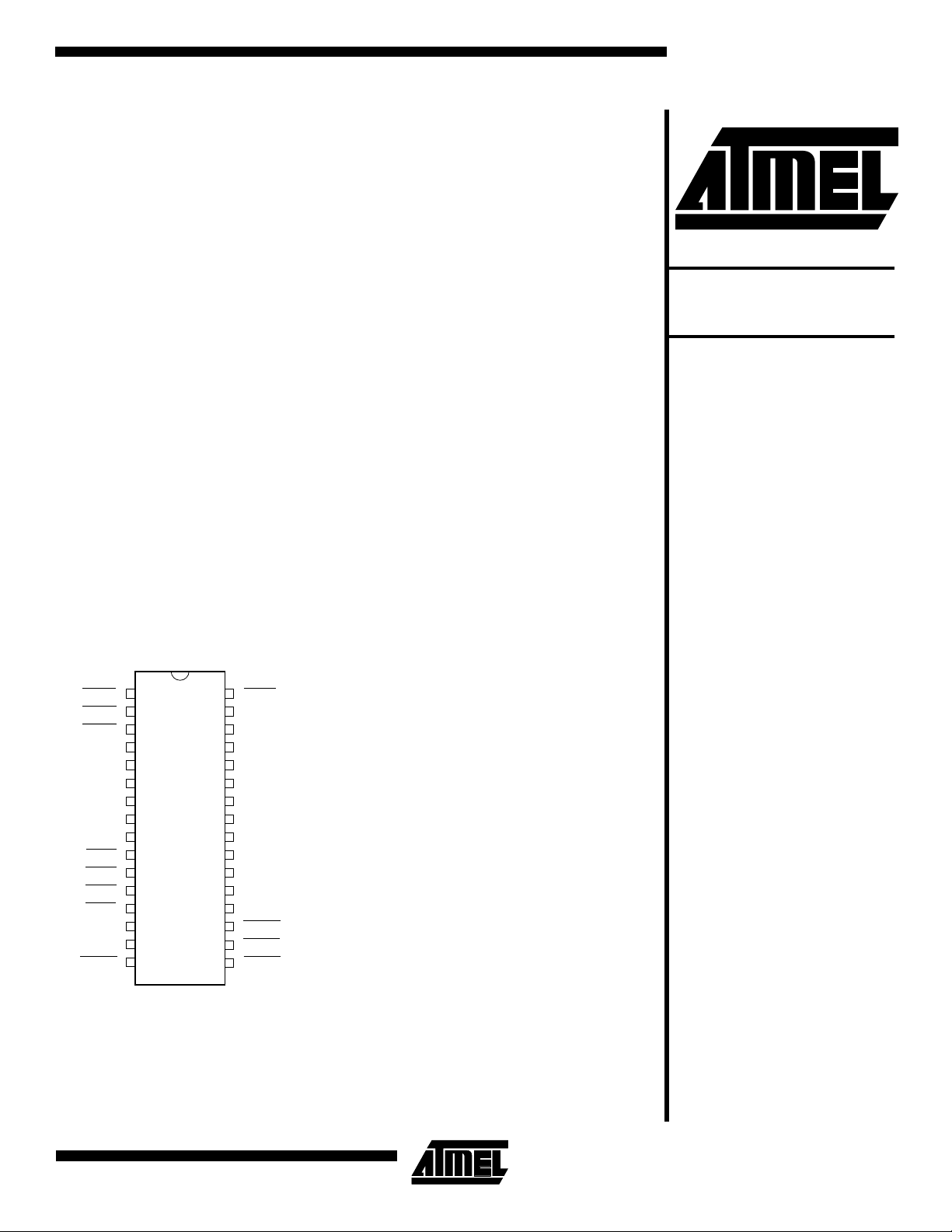
Pin Configurations
SOIC/DIP/Cerdip
PWR2
PWR3
PWR4
VCC5
VSS
OSC1
OSC2
LFT
VCCA
OVL4
OVL3
OVL2
OVL1
VREF
GND
STAT4
1
2
3
4
5
6
7
8
9
10
11
12
13
14
15
16
32
31
30
29
28
27
26
25
24
23
22
21
20
19
18
17
PWR1
DP4
DM4
DP3
DM3
GND
DP2
DM2
VCC3
DP1
XDM1
DP0
DM0
STAT1
STAT2
STAT3
0738A-A
1
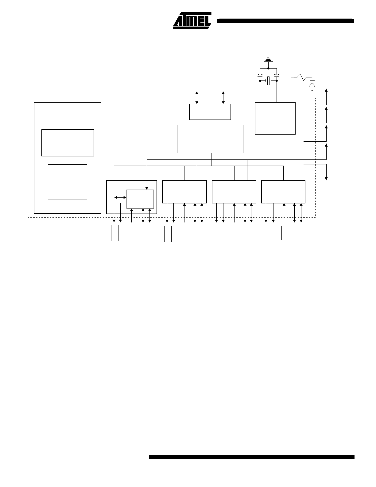
Block Diagram
STAT3
DP0
PWR3
OVL3
DM3
DP3
OSC2
OSC1
TIMING
AND
CONTROL
PORT 4
STAT4
PWR4
LFT
OVL4
DM4
VCC5
VCC3
VCCA
VREF
GND
DP4
DM0
HUB CONTROLLER
Serial Interface
Engine
Endpoint 0
PORT 1
Endpoint 1
Note: 1. This document assumes that the reader is familiar with the Universal Serial Bus and therefore only describes the unique
features of the AT43311 chip. For detailed information about the USB and its operation, the reader should refer to the Universal Serial Bus Specification Version 1.0, January 19, 1996.
STAT1
Overcurrent
Protection/
Reporting
OVL1
PWR1
DM1
DP1
PORT 2 PORT 3
STAT2
PWR2
PORT 0
REPEATER
DM2
OVL2
HUB
DP2
2
AT43311

AT43311
Pin Description
Pin Description Pin Type Description
OSC1 I Oscillator Input. Input to the inverting 6 MHz oscillator amplifier.
OSC2 O Oscillator Output. Output of the inverting oscillator amplifier.
LFT I
VREF I Reference Voltage. This is an input pin that should be connected to an external
DP0 B Upstream Plus USB I/O. This pin should be connected to VCC3 through an external
DM0 B Upstream Minus USB I/O
DP[1:4] B Port Plus USB I/O. These pins should be connected to VSS through external 1.5K Ω
DM[1:4] B
OVL[1:4]
PWR[1:4]
I Port Overload. These are the input signals used to indicate to the AT43311 that there
OD Power Switch. These are the output signals used to enable or disable the external
PLL Filter. For proper operation of the PLL, this pin should be connected through a
100 Ω resistor and 10 nF capacitor to ground (V
(see Figure 1–Power Supply Connection).
voltage source. VREF is used internally as the reference voltage by the overload
protection circuit to decide whether there is a problem with a port’s power supply.
1.5K Ω pullup resistor. DP0 and DM0 form the full speed differential signal pin pairs
connected to the Host Controller or an upstream Hub.
resistors. DP[1:4] and DM[1:4] are the differential signal pin pairs to connect
downstream USB devices.
Port Minus USB I/O. These pins should be connected to VSS through external 15K Ω
resistors. DP[1:4] and DM[1:4] are the differential signal pin pairs to connect
downstream USB devices.
is a power supply problem with the port. If OVL
the corresponding PWR[1:4]
voltage regulator supplying power to the port. PWR[1:4]
supply problem is detected at OVL[1:4]
For proper operation of PWR[1:4]
required.
pin and report the status to the USB Host.
.
, an external pull-up resistor of 10K Ω to VCC5 is
) in parallel with a 2.2 nF capacitor
SS
is asserted, the AT433 11 will assert
is de-asserted when a power
STAT[1:4]
V
CC3
V
CC5
V
CCA
GND V Ground
O Connect Status. These are output pins indicating that a port is properly connected.
STAT[1:4]
V 3.3V Power Supply, used for the USB interface
V 5V Power Supply, main power supply for the AT43311
V 5V Analog Power Supply
is asserted when the port is enabled.
3

USB Hub Description
Hub Repeater
The hub repeater i s responsibl e for port conn ectivity set up
and tear-down. The rep eater a lso support s exception handling such as bus fault detection and r ecovery, and connect/disconnect detection.
When a SOP to ken is detecte d on the upst ream port,
Port0, the AT43311 determines the speed of the transfer.
A USB hub must not propagate a full speed transfer to a
low speed port due to the possible misinterpretation of the
data. The AT43311 will propagate the packet to all enabled
downstream ports.
Note: See USB Specification for further detail on bus
states
The AT43311 supports do wnstream dat a signaling at bo th
1.5 Mbps and 12 Mbps. Devices attached to the downstream ports are either full speed or low speed depending
on which data line (DP or DM) is pulled hi gh. If a por t is
enumerated as low speed, the output buffers operate at a
slew rate between 75 ns and 300 ns. The AT43311 will not
propagate any traffic to that port unless it is prefaced with a
preamble PID. Low speed data fo llowing the preambl e PID
is propagated to both low and full speed devices. The
AT43311 will enable low speed drivers within four fullspeed bit times of the last bit of a preamble PID, and will
disable the drivers at the end of an EOP. The upstream
traffic from any port to the host is prop agated by Port0
using the full speed 4-20 ns slew rate drivers.
All ports are independently driven and monitored on the DP
and DM pins. The AT43311 detects or generates the ‘J’,
‘K’, and SE0 bus s ignal ing st ates. E ach hu b port has s ingle-ended and differential receivers on its DP and DM lines.
The ports’ I/O buffers comply to the voltage levels and drive
requirements as specified in the USB Specifications Revision 1.0.
The Hub Repeater implements a frame timer that is timed
by the 12 MHz USB clock and is reset every time an SOF
token is received from the Host.
Hub Controller
The hub controller ma nages an d records the op eratio ns of
the AT43311. During enumeration, the controller sends the
host the configuration information. The controller also
allows the host to retrieve the status of the downstream
ports, and power the downs tream ports. The control ler
applies power to the downstream ports on a per port basi s.
After configuration , the co ntrol le r wil l e nab le the p owe r t o a
downstream port upon a SetPortPower command by the
host. The controller supports two endpoints and a Control
Status register.
Serial Interface Engine
The Serial Interface Engine (SIE) converts data between
the serialized USB format and usable data for the controller
and repeater. To carry out these tasks, the SIE is able to
detect or generate USB signaling. Once a valid operation is
detected, the SIE translates the data depending on the
operation.
During a reception, the SIE will use the high speed clock
supplied by the PLL to help synchronize and separate the
synchronization informa tion from th e data. The data mu st
be decoded before the SIE may supply the packet ID to the
controller and repeater.
The USB protocol uses Cyclical Redundancy Check
(CRC), Non Return to Zero Invert (NRZI) data encoding
and bit stuffi ng to i mprov e the re liabil ity of data trans fers.
The SIE must decode the NR ZI and strip o ff the stuffe d bit
to determine the actual data. The CRC information will be
used by the SIE to determine if a transmission error has
occurred. If an error has occurred, the SIE will correct the
data using CRC algorithms.
Control Status Register
Bit Function Value Description
0 Hub configuration status
1 Hub remote wakeup status
2 Endpoint0 STALL status 0
3 Endpoint1 STALL status 0
4
AT43311
0
1
0
1
1
1
Set to 0 or 1 by a Set_Configuration Request
Set to 0 or 1 by ClearFeature or SetFeature request
Default value is 0
Endpoint0 is stalled
Endpoint0 is stalled
Endpoint1 is not stalled
Endpoint1 is stalled
Hub is not currently configured
Hub is currently configured
Hub is currently not enabled to request remote wakeup
Hub is currently enables to request remote wakeup

AT43311
Endpoint0
Endpoint0 i s th e A T4331 1’s defa ult en dpoi nt u sed f or en umeration of the Hub and exchange of configuration information and requests between the Host and th e AT43311.
Endpoint0 supports control transfers.
Standard USB Device Requests and class-specific Hub
Requests are supported through Endpoint0.
The Hub Controller supports the fol lowing descriptors
through Endpoint0 (Descriptors are described in detail in
the Descriptors Section of this document):
• Device Descriptor
• Configuration Descriptor
• Interface Descriptor
• Endpoint Descriptor
• Hub Descriptor
Endpoint1
Endpoint1 is used by the Hub Controller to send status
change information to the Hos t. Endpoint1 supp orts interrupt transfers.
The Hub Controller samples the c hanges at th e end of
every frame at time marker EO F2 in preparation for a
potential data transfer in the subsequent frame. The sampled information is stored as a byte in Statu s Chang e Register using a bitmap scheme.
Each bit in the Status Change Register corresponds to one
port as shown below.
An IN Token packet from the Host to Endpoi nt1 ind icate s a
request for port change status. If the Hub has not detected
any change on the port s or a ny change s in the hub itself,
then all bits in this register will be 0 and the Hub Controller
will return a NAK to requests on Endpoint1. If a change in
the port status exists, the Hub Controller will transfer the
whole byte. The Hub Controller will continue to report a status change when polled until that particular change has
been removed by a ClearP ortFeature reques t from the
Host. No status chang e will be reporte d by Endpoi nt1 unti l
the AT43311 has been enumerated and configured by the
Host through Endpoint0.
Power Management
The AT43311 is designed to be powered from the USB
bus. As such, the power co nsumption for the AT43311
itself is less th an 100 m A. Howev er, down stream devices
require separate power supplies. The AT43311 monitors
and controls each power supply to the individual downstream devices.
Careful design and selection of the power switch is
required to meet the USB specification. The USB specifications requires that the volta ge drop at th e power switch be
no more than 100 mV. USB requirements specify that a
downstream device may use a maximum of 500 mA. These
conditions are best met by using a MOSFET switch with an
on resistance of 200 m
As a sample power circuit, consid er a P-chan nel enhan cement mode MOSFET. The condition of the port’s power is
monitored at the output side of the P MOS switch whi ch is
connected to the port’s OVL[1:4]
condition, the MOSFE T swit ch’s i nte rnal resista nce ca uses
the MOSFET’s output voltage to drop at the OVL[1:4]
the MOSFET’s out put voltage dr ops to less than the voltage at the VREF voltage reference pin, the AT4331 1 interprets this drop as a n overcurrent c ondition. The AT43311
does internal filtering to m ake su re that spurious o r switch ing transients are ignore d. If an overcurrent condit ion
exists, the AT43 311 rem oves the power from t hat port b y
de-activating the port’s PWR[1:4]
tion to the Host.
Ω or less.
pin. During an overcurrent
pin. If
pin and reports the condi-
Status Change Register
Bit Function Value Meaning
0 Hub status change 0
1
1 Port1 status change 0
1
2 Port2 status change
3 Port3 status change
4 Port4 status change
5-7 Reserved 0 Default values
0
1
0
1
0
1
No change in status
Change in status detected
No change in status
Change in status detected
No change in status
Change in status detected
No change in status
Change in status detected
No change in status
Change in status detected
5
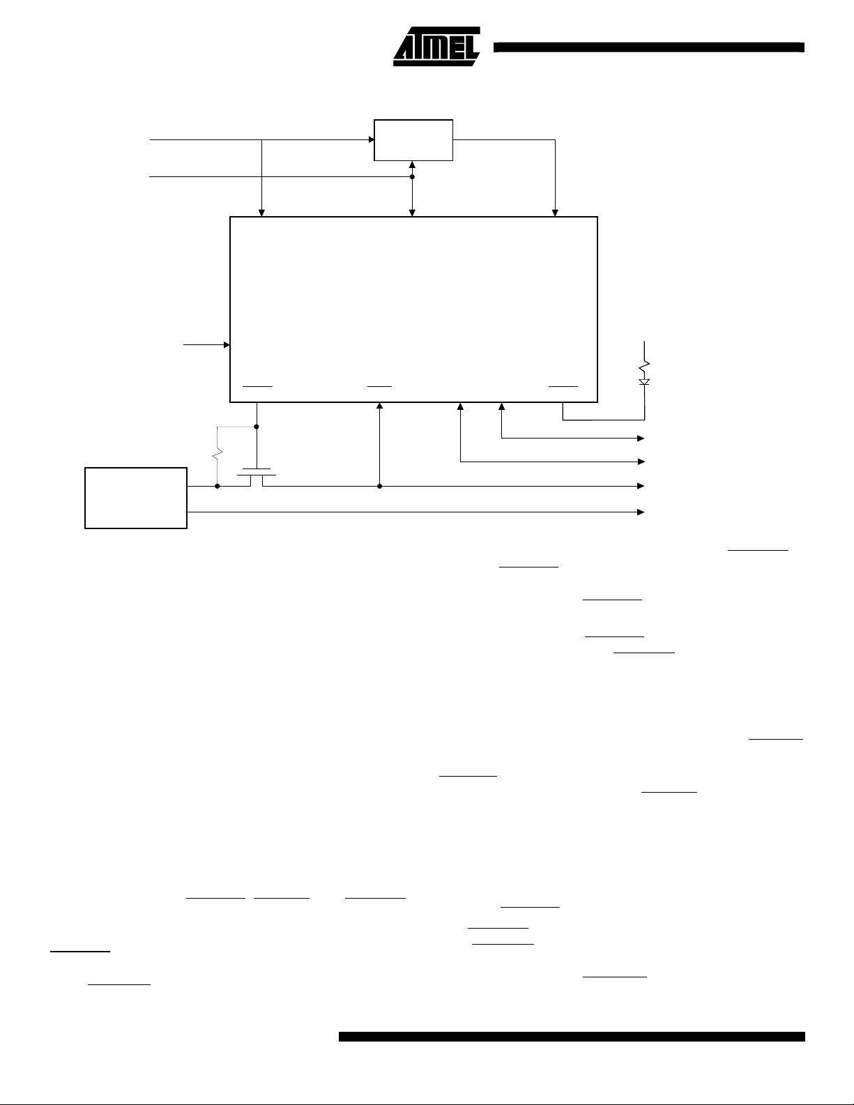
Figure 1. Power Supply Connection
From upstream power regulator
VCC5 GND VCC3
VREF
3V REG.
AT43311
5.5V
PWR
5V POWER
SUPPLY
OVL
Figure 1 illustrates an example of the power supply connection for a AT43311 port.
Careful conside ration mu st be taken to avoid lar ge grou nd
current surges. There is the possibility that the upstream
device and the self powered device will be sourced from
different electri cal powe r outle ts which share no comm on
ground.
When designing the local power supply for the AT4 3311 or
a self powered device , local 5 V power must be isolated.
This isolation can be achieved th rough a transform er or by
proper design of the switching power suppl y. The GND of
the Hub or device can then be safely connected to the
upstream ports ground line for proper operation of the USB
signals.
Even though the devices in a USB network share a common ground (VSS), the t wo 5V supply volta ges of the
AT43311 based hub (the upstream’s bus power and the
local power) must not be connected under any condition.
Port [1:4] Power Control
Each port has signals for port power management and for
port status feedback (PWR[1:4 ]
, OVL[1:4], and STAT[1:4]).
The AT43311 monitors and switches the power to each
port individually.
PWR[1:4]
are open drain outputs that control the power to
the downstream ports. The AT43311 asserts a low value to
ports PWR[1:4]
to turn on the power to the port. During
DP DM
power up, reset, and initialization of the Hu b, PWR[1:4]
in-active. PWR[1:4]
STAT
To downstream device
VCC5
VSS
is
is asserted when the Host instructs the
Hub to power the p ort through the S etPortPower = O N
command. Additionally PWR[1:4]
is de-asserted by the Hub
when an overcurrent condition is detected at the port.
For proper operation of PWR[1:4]
tor to VCC5 is required f or PWR[1:4]
, an external pull-up resis-
pins. To control the
power to the port, any switch with a low voltage d rop with
full power applied is acceptable . The AT43311 is desi gned
for a simple, low cost P-c hannel MOS FET to us e as the
switch.
To detect a port overload, the AT43311 compares OVL[1:4]
to a common VREF defined by the designer.
OVL[1:4]
respective downstre am port. If OVL[1:4]
should be attached to the power supply of the
drops below the
reference voltage VREF for more than 1 ms, the AT43311
treats the drop in voltage as a fault condition on the port’s
power supply. Upon this fault condition, the AT43311 sets
the port’s PORT_OVER_CURRENT status bit and the
port’s C_PORT_OVER_CURRENT bit. The AT43311 will
additionally shut off the power to the port by de-activating
the port’s PWR[1:4]
The STAT[1:4]
tion. STAT[1:4]
signal.
pins are not required by the USB specifica-
provide feedback to the user whenever a
device is properly connected to the port. An LED and series
resistor connected to STAT[1:4]
can be used to provide
6
AT43311
AT43311
visual feedback. The default state of STAT[1:4]
After a port is enabled AT43311 will assert the port’s
STAT[1 :4]
.
is inactive.
Oscillator and Phase-Locked-Loop
To reduce EMI and power dissip ation in the system, the
AT43311 on-chip oscillator is designe d to ope rate wit h a 6
MHz external crystal. An on-chip PLL generates the high
frequency for the clock/data separator of the Serial Interface Engine. In the suspended stat e, the oscillator circuitry
is turned off.
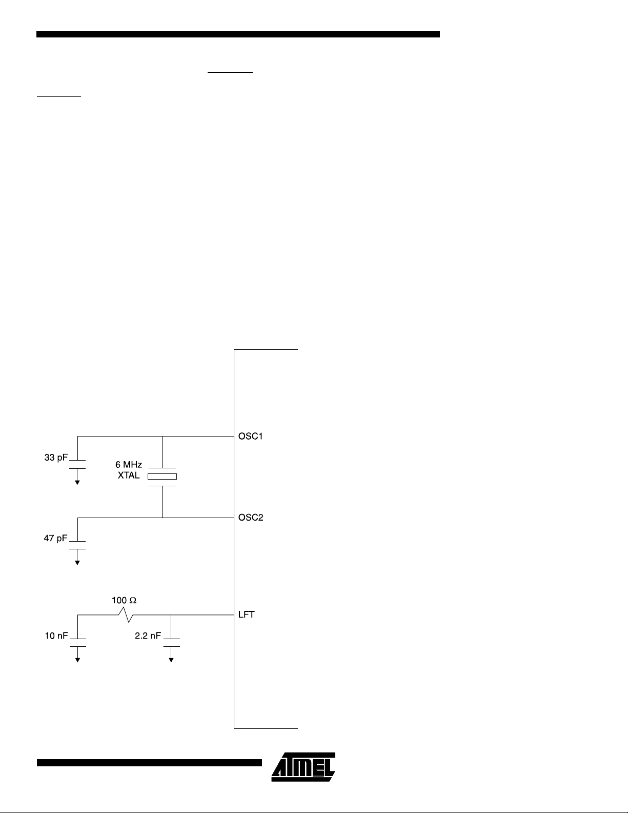
A 6 MHz parallel resonance quartz crystal with a load
capacitance of approximately 10 pF is recommended. If the
crystal load capacitor is larger, external capacitors added to
pins OSC1 and OSC2 are recommended. The values for
these capacitors depends on the crystal and the layout of
the board, but typically are 33 pF at OSC1 an d 47 pF at
OSC2. If the crystal used cannot tolerate the drive level s of
the oscillator, a series resistor between OSC2 and the crystal pin may be used.
Figure 2. Oscillator and PLL Connection
Figure 2 shows how to properly connect the oscillator for
the AT43311. Ceramic resonators are not recommended
due to the frequency stability required by the USB specification (0.25%).
If desired, the clock c an be external ly sourced. To clock
externally, connect the clock source to the OSC1 pin, while
leaving the OSC2 pin floating. The switching level at the
OSC1 pin can be as low as 0 .47V ( see electrical specifi cations). A CMOS device is required to drive this pin to maintain good noise margins at the low switching level.
For proper operation of the PLL, see Figure 1–Power Supply Connection.
To provide the best operating condition for the AT43311,
careful consideration of the power supply connections are
recommended. Use short, low impedance connections to
all power supply lines: VCC5, VCC3, VCCA , and VSS with
0.1 µF decoupling capacitors of high quality adjacent to the
device pins.
Descriptors
The Hub Controller supports the following standard USB
descriptors: Device, Configurat ion, Interface, an d Endpoint
Descriptors, as well as the class specific Hub Descriptor.
All the required Standard Requests and Hub Class-Specific
Requests are supported by the AT43311’s Hub Controller.
7

Device Descriptor
The Device Descriptor provides general information about the AT43311 Hub.
Offset Field Description Size (bytes) Value
0 bLength Define size of descriptor = 18 bytes 1 12H
1 bDescriptorType Device descriptor type 1 01H
2 bcdUSB USB Spec. Release Number = Rev 1.0 2 00H
4 bDeviceClass Class code = HUB_CLASSCODE = 09 1 09 H
5 bDeviceSubClass Subclass code 1 00H
6 bDeviceProtocol Protocol code 1 00H
7 wMaxPacketSize0 Max. packet size for Endpoint0 = 8-bytes 1 08H
9 idVendor Vendor ID = Atmel Corporation 2 EBH
10 idProduct Product ID = AT43311 2 11H
01H
03H
33H
12 bcdDevice
14 iManufacturer Index of string descriptor describing
15 iProduct Index of string descriptor describing product =
16 iSerialNumber Index of string descriptor describing device’s
17 bNumConfigurations Number of possible configurations = 1 1 01H
Device release number
Example: Rev A0 YY = 01 ZZ = 00
Rev B1 YY = 02 ZZ = 01
manufacturer = not supported
not supported
serial no. = not supported
2 ZZH
YYH
100H
100H
100H
8
AT43311

AT43311
Configuration Descriptor
This Configuration Descriptor provides information about the AT43311’s configuration.
Offset Field Description Size (bytes) Value
0 bLength Define size of this descriptor = 9 bytes 1 09H
1 bDescriptorType Descriptor type = Configuration 1 02H
2 wTotalLength
4 bNumInterface
5 bConfigurationValue Argument value for this configuration to be used
6 iConfiguration Index of string descriptor describing this
7 bmAttributes Configuration characteristics = Bus and Self
8 MaxPower Maximum power consumption of USB device
Total length of data returned for this
configuration. Consists of the combined length
of configuration, interface, endpoint and hub
descriptors = 52 bytes
Number of interfaces supported by this
configuration.
by Set Configuration command
configuration (not supported).
Powered with Remote Wakeup
from bus = 100 mA
222H
101H
101H
100H
1E0H
132H
Interface Descriptor
The Interface Descriptor provides information about the single interface which the AT43311 supports.
Offset Field Description Size (bytes) Value
0 bLength Define size of this descriptor = 9 bytes. 1 09H
1 bDescriptorT ype Descriptor type = Interface 1 04H
00H
2 bInterfaceNumber Number of interface = 1, index = 0 1 00H
3 bAlternateSetting Alternate setting value for the interface identified
in the prior field = 0
4 bNumEndpoints Number of endpoints used by this interface = 1 1 01H
5 bInterfaceClass Class code = HUB_CLASSCODE = 09 1 09H
6 bInterfaceSubClass Subclass code = 0 1 00H
7 bInterfaceProtocol Protocol code = 0 1 00H
8 iInterface Index of string descriptor describing this
interface = not supported
100H
100H
9

Endpoint Descriptor
The Endpoint Descriptor describes the Endpoint1 Descriptor which the Hub uses for status change report.
Offset Field Description Size (bytes) Value
0 bLength Define size of this descriptor = 7 bytes 1 07H
1 bDescriptorType Descriptor type = endpoint 1 05H
2 bEndpointAddress The address of the IN endpoint 1 81H
3 bmAttributes Endpoint1 attribute =IN, Interrupt Transfer 1 03H
(1)
4 wMaxPacketSize Max. packet size Endpoint1 is capable of
sending = 1 byte
6 bInterval Interval for polling endpoint for data transfers 1 FFH
Note: 1. Th ere is no endpoi nt d escriptor for Endpoint0.
201H
Hub Descriptor
The Hub Descriptor describes the AT43311’s Hub and ports.
Offset Field Definition Size (bytes) Value
0 bDescLength Define size of this descriptor = 9 bytes 1 09H
1 bDesriptorType Descriptor Type = HUB_DESCRIPTOR = 29 1 29H
2 bNbrPorts Number of downstream ports = 4 1 04H
3 wHubCharacteristics Hub’s characteristics:
= Individual power switching
= Hub is not part of a compound device
= Individual Port Over-current Protection
5 bPwrOn2PwrGood Time from the time power-on sequence begins
on a port until power is good on that port = 100
ms.
6 bHubContrCurrent Maximum current requirements of the hub
electronics = 100 mA.
209H
132H
164H
00H
00H
7 DeviceRemovable Indicates if a port has removable device. All
downstream ports have removable devices
8 PortPwrCtrlMask Indicates if a port is not affected by gang-mode
power control request. All the AT43311’s ports
require manual SetPortFeature
(PORT_POWER) request to control the port’s
power state.
10
AT43311
100H
11EH

AT43311
Standard Requests
All required Standard Requests are supported by the
AT43311. Standard Requests, or commands, are sent to
the AT43311 from the Host on the AT43311’s defau lt pipe,
endpoint0. These requests are made using control transfers to endpoint0. The request and request pa rameters are
sent in a Setup packet w hich c onsists of eig ht bytes. The
following sections describe which req uests are supported
by the AT43311 and the corresponding responses as well
as those requests not s upported and responded wi th a
STALL packet.
Clear Device Feature
A Clear Device Feature will disable its remote wakeup feature when the setup packet is:
Field Value
bmRequestType Byte 0 x0000000B
bRequest Byte 1 01H
wValue Byte 2
Byte 3
wIndex Byte 4
Byte 5
wLength Byte 6
Byte 7
01H
00H
00H
00H
00H
00H
Clear Endpoint Feature
The Clear Endpoint Feature request causes the AT 43311
to clear an endpoint’s stall status bit if the condition causing
the stall has been removed. A Clear Endpoint Feature
occurs if a setup packet from the Host is decoded as:
Field V alue
bmRequestType Byte 0 x0000002B
bRequest Byte 1 01H
wValue Byte 2
Byte 3
wIndex Byte 4
Byte 5
wLength Byte 6
Byte 7
00H
00H
00H for EP0
81H for EP1
00H
00H
00H
Get_Configuration
Get_Configuration returns one byte of data. Bit 0 will be a
copy of bit 0 of the Controller_Status Register. All other bits
will be set to 0. This action will be taken, if the Setup packet
from host is decoded as:
Field Value
bmRequestType Byte 0 10000000B
Clear Interface Feature
AT43311 does no t support thi s feature and wi ll respond
with a STALL if a setup packet from the Host is decoded
as:
Field Value
bmRequestType Byte 0 x0000001B
bRequest Byte 1 01H
wValue
wIndex
wLength
Byte 2
Byte 3
Byte 4
Byte 5
Byte 6
Byte 7
xxH
xxH
xxH
xxH
xxH
xxH
bRequest Byte 1 08H
wValue Byte 2
Byte 3
wIndex Byte 4
Byte 5
wLength Byte 6
Byte 7
00H
00H
00H
00H
01H
00H
11

Get_Descriptor
Get_Descriptor returns the requ ested desc riptor. The la st
word of the Get_Descriptor request specifies the number of
bytes the AT43311 is to return. If the requested descriptor
is longer than the requested number of bytes, AT43311 will
return only the requested number of bytes from the top of
the descriptor. If the requested descriptor is shorter than
the requested number of bytes, then the AT43311 indicates
the end of the control transfer by sending a short data
packet.
The requested nu mber of bytes from the top of AT 43311’ s
Device Descriptor will be returned, if the Setup packet from
host is decoded as:
Field Value
bmRequestType Byte 0 10000000B
bRequest Byte 1 06H
wValue Byte 2
Byte 3
wIndex Byte 4
Byte 5
00H
01H
00H
00H
Get_Interface
The AT43311 has a single i nterface wit h a value of 0. If it
receives a Get_Interface Request with the value of 0000H
as wIndex (bytes 2 and 3), the AT433 11 w ill retu rn a sing le
byte with a value of 00H. For any other value of wIndex the
AT43311 will return a STALL.
Field Value
bmRequestType Byte 0 10000001B
bRequest Byte 1 0AH
wValue Byte 2
Byte 3
wIndex Byte 4
Byte 5
wLength Byte 6
Byte 7
00H
00H
00H
00H
01H
00H
Get Device Status
If the Setup packet from host is decoded as:
Field Value
wLength Byte 6
Byte 7
The requested number of bytes from AT43311’s Configuration Descriptor, Interface Descriptor, and Endpoint Descriptor will be retu rned, if t he Setup p acket from the Host is
decoded as:
Field Value
bmRequestType Byte 0 10000000B
bRequest Byte 1 06H
wValue Byte 2
Byte 3
wIndex Byte 4
Byte 5
wLength Byte 6
Byte 7
# of bytes
requested
00H
02H
00H
00H
# of bytes
requested
bmRequestType Byte 0 10000000B
bRequest Byte 1 00H
wValue Byte 2
Byte 3
wIndex Byte 4
Byte 5
wLength Byte 6
Byte 7
The Hub will return two bytes of da ta, byte 0 and byte 1, in
little endian order:
Byte 0, Bit 0 = 1, identifying the AT43311 as a self powered device.
Byte 0, Bit 1 = copy of bit 1 of the Controller_Status
Register. This bit reflects whether the AT43311’s
remote wakeup capability is enabled or disabled.
All other bits are set to 0.
00H
00H
00H
00H
02H
00H
12
AT43311

AT43311
Get Interface Status
If the Setup packet from host is decoded as:
Field Value
bmRequestType Byte 0 10000001B
bRequest Byte 1 0x00
wValue Byte 2
Byte 3
wIndex Byte 4
Byte 5
wLength Byte 6
Byte 7
The Hub will respond with two bytes of data with all 0 value.
0x00
0x00
0xxx
0xxx
0x02
0x00
Get Endpoint Status
Get Endpoint Status returns two -bytes of data indicating
the stall status of the en dpoint. The first bit of the first byte
returned reflects the status of the endpoint stall status bits
of the Controller_Status Register described in section 3.6.
These bits are set or cleared depending whether the endpoint is stalled or not:
Current Endpoint Status
Stalled 01H 00H
Not stalled 00H 00H
Get Endpoint Status will execute if the following setup
packet is decoded as:
First
Byte
Second
Byte
Set_Address
Set_Address sets the Hub’s address. The AT43311 will
save the value of bytes 2 and 3 into a temporar y buffer.
After successful completion of the status stage, the
AT43311 transfers the temporary value into the
Hub_Address Register. The Hub_Address will be used as
the Hub’s addres s in al l future transacti ons. Se t_Address
will occur if the Setup packet from the Host is decoded as:
Field Value
bmRequestType Byte 0 x0000000B
bRequest Byte 1 05H
wValue Byte 2
Byte 3
wIndex Byte 4
Byte 5
wLength Byte 6
Byte 7
Device
Address
00H
00H
00H
00H
Set_Configuration
Set_Configuration sets bit 0 of the Controller_Status Register according to the value of byte 2 of the Setup packet.
The AT43311 has only one configuration. The AT43311 will
only set the bit if byte 2 is either 00H or 01H, and bytes 3 to
7 are all zeroes. For all other values, the Hub will respond
with a STALL handshake packet. Set_Configuration occurs
if the Setup packet from host is decoded as:
Field Value
bmRequestType Byte 0 x0000000B
Field Value
bmRequestType Byte 0 10000010B
bRequest Byte 1 00H
wValue Byte 2
Byte 3
wIndex Byte 4
Byte 5
wLength Byte 6
Byte 7
x0000001B for EP0
10000001B for EP1
00H
00H
00H
02H
00H
bRequest Byte 1 09H
wValue Byte 2
Byte 3
wIndex Byte 4
Byte 5
wLength Byte 6
Byte 7
00H or 01H
00H
00H
00H
00H
00H
13

Set_Descriptor
The AT43311 does not support this request. In response to
this request, the AT43311 will send a STALL handshake
packet. The Set_Descriptor occurs if the Setup packet from
the Host is decoded as:
Set Endpoint Feature
Set Endpoint Feature sets the stall status bit of the
Controller_Status Register. The stalled endpoint will exhibit
the same behavior as in a stall c ondition. This feature is
activated if a setup packet from the Host is decoded as:
Field Value
bmRequestType Byte 0 00000000B
bRequest Byte 1 07H
wValue Byte 2
Byte 3
wIndex Byte 4
Byte 5
wLength Byte 6
Byte 7
xxH
xxH
xxH
xxH
xxH
xxH
Set Device Feature
Set Device Feature enables the remote wakeup feature if a
setup packet from the Host is decoded as:
Field Value
bmRequestType Byte 0 x0000000B
bRequest Byte 1 03H
wValue Byte 2
Byte 3
wIndex Byte 4
Byte 5
wLength Byte 6
Byte 7
01H
00H
00H
00H
00H
00H
Field Value
bmRequestType Byte 0 x0000010B
bRequest Byte 1 03H
wValue Byte 2
Byte 3
wIndex Byte 4
Byte 5
wLength Byte 6
Byte 7
00H
00H
00H for EP0
81H for EP1
00H
00H
00H
Set_Interface
The AT43311 has a single interface and responds with a
STALL hands hake packet if a Set_Inte rface reque st is
received with a value other than 0000 H as a wV alu e (b yte s
2 and 3).
Field Value
bmRequestType Byte 0 x0000001B
bRequest Byte 1 0BH
wValue Byte 2
Byte 3
wIndex Byte 4
Byte 5
00H
00H
00H
00H
Set Interface Feature
AT43311 does no t support thi s feature and wi ll respond
with a STALL if a setup packet from the Host is decoded
as:
Field Value
bmRequestType Byte 0 x0000001B
bRequest Byte 1 03H
wValue Byte 2
Byte 3
wIndex Byte 4
Byte 5
wLength Byte 6
Byte 7
14
AT43311
xxH
xxH
xxH
xxH
xxH
xxH
wLength Byte 6
Byte 7
00H
00H
Sync_Frame
This request is for endpoin ts with isoch ronous trans fers
only which the AT43311 does not suppor t. AT43311 will
send a STALL packet if the setup packe t from the Host i s
decoded as:
Field Value
bmRequestType Byte 0 10000001B
bRequest Byte 1 0CH
wValue Byte 2
Byte 3
wIndex Byte 4
Byte 5
wLength Byte 6
Byte 7
xxH
xxH
xxH
xxH
xxH
xxH

AT43311
Hub-specific Requests
All required Hub-specific re quests are supported by the
AT43311’s Hub Controll er. Hub-sp ecific re quests or commands are sent from the Host to t he AT43311 usi ng the
default pipe (Endp oint0). Hub-specific requests are m ade
using control tra nsfers. The requ est an d request parameters are sent in a setup packet consisting of eight bytes.
Clear_Hub_Feature
Clear_Hub_Feature resets a value rep orted in the Hub
Controller status. The status relates to the local power and
over current. AT43311 is a self-powered hub with a buspowered SIE and does not report over-current on a global
basis.
The Hub Controller will disable the reporting of Local Power
Status (C_HUB_LOCAL_POWER) if the setup packet from
the Host is decoded as:
Field Value
bmRequestType Byte 0 x0100000B
bRequest Byte 1 01BH
wValue Byte 2
Byte 3
00H
00H
Clear_Port_Feature
Clear_Port_Feature disables a port feature. Note that only
the relevant Clear Port commands are supported (see
CLEAR_PORT Features Table).
For example, the PORT_LOW_SPEED value is determined
by the operation of the port of the attached device. Upon an
invalid req uest (e.g. a CLEAR_P ORT request for
PORT_LOW_SPEED), the AT43311 will return a STALL
status to the host.
CLEAR_PORT Features Table
Port Feature
PORT_CONNECTION N N
PORT_ENABLE Y Y
PORT_SUSPEND Y Y
PORT_OVER_CURRENT Y N
PORT_RESET N Y
PORT_POWER Y Y
PORT_LOW_SPEED N N
ClearPort
Feature
SetPort
Feature
wIndex Byte 4
Byte 5
wLength Byte 6
Byte 7
AT43311 will respond with a STALL if the setup packet
from the Host requests the Hub Controller to clear the Over
Current Indicator (C_HUB_OVER_CURRENT):
Field Value
bmRequestType Byte 0 x0100000B
bRequest Byte 1 01H
wValue Byte 2
Byte 3
wIndex Byte 4
Byte 5
wLength Byte 6
Byte 7
00H
00H
00H
00H
01H
00H
00H
00H
00H
00H
The Hub Controller will respond to a Clear Port Feature
request if the setup packet from the Host is decoded as:
Field Value
bmRequestType Byte 0 x0100011B
bRequest Byte 1 01H
wValue Byte 2
Byte 3
wIndex Byte 4
Byte 5
wLength Byte 6
Byte 7
See Port
Feature
Selector Table
Port
Number
00H
00H
15

Port Feature Selector Table
Feature Value
PORT_CONNECTION 00H
PORT_ENABLE 01H
PORT_SUSPEND 02H
PORT_OVER_CURRENT 03H
PORT_RESET 04H
PORT_POWER 08H
PORT_LOW _SPEED 09H
C_PORT_CONNECTION 10H
C_PORT_ENABLE 11H
C_PORT_SUSPEND 12H
C_PORT_OVER_CURRENT 13H
C_PORT_RESET 14H
Get_Hub_Descriptor
Get_Hub_Descriptor return s the Hub Descr iptor. The l ast
word of the Get_Hub_Descriptor request specifies the
number of bytes AT43311 is to return. If the requested
number of bytes is less than the 9-bytes le ngth of the Hub
Descriptor, AT43311 will return only the request ed number
of bytes from the top of the descriptor. If the requested
number of bytes is more than 9, then the returned d ata wil l
be padded with trailing bytes of zeroes.
This action will be taken if the Setup packet from the Host is
decoded as:
Field Value
bmRequestType Byte 0 10100000B
bRequest Byte 1 06H
wValue Byte 2
Byte 3
wIndex Byte 4
Byte 5
29H
00H
00H
00H
The Hub Contro ller w ill re spond w ith a STA LL if P ort0 or a
port higher than Port4 is addressed in this request.
Get_Bus_State
When a Get_Bus_State is detected , the Hub Co ntroller wi ll
sample the bus status of Ports 1, 2, 3 and 4, at each E OF2
and will store the value in a register known as the
Port_Bus_State registers. The value of the D- signal (pin
DM[1:4]) will be in bi t 0 and the value o f the D+ signal
(DP[1:4]) will be in bit 1of each port’s Port_Bus_State register. All other bits will be 0. The values of t hese two regi ster
bits will be transferred to the Host upon receipt of the
Get_Bus_State request, if the setup packet fr om Host is
decoded as:
Field Value
bmRequestType Byte 0 10100011B
bRequest Byte 1 02H
wValue Byte 2
Byte 3
wIndex Byte 4
Byte 5
wLength Byte 6
Byte 7
00H
00H
Port
Number
01H
00H
wLength Byte 6
Byte 7
Number of Bytes
Requested
The Hub Contro ller w ill re spond w ith a STA LL if P ort0 or a
port higher than Port4 is addressed in this request.
16
AT43311

AT43311
Get_Hub_Status
Get_Hub_Status returns the current Hub status that has changed sin ce the p revious acknowled gment of the setup pa cket
of the Host.
The Hub will returned two words of data as described in the following two tables. Word0 is the Hub Status Field, wHubStatus, and Word1 is the Hub Change Field,wHubChange.
Hub Status Field, wHubStatus
Bit Description
Local Power Status, indicates the state of the local power supply
0
0 = Local power supply good
1 = Local power supply lost
1
2-15 Reserved. Always read as 0’s
Hub Change Field, wHubChange
Bit Description
0
1
2-15 Reserved. Always read as 0’s.
A Get_Hub_Status will occur if the setup packet is decoded
as:
Field Value
bmRequestType Byte 0 10100000B
bRequest Byte 1 00H
wValue Byte 2
Over-Current Indicator, indicates over-current condition on a global hub basis. AT43311 reports over current
condition on a per port basis therefore this bit is always read as 0
Local Power Status Change, C_HUB_LOCAL_POWER, corresponds to bit 0 of wHubStatus
0 = No change has occurred in local power status
1 = Local power status has changed
Over-Current Indicator Change, C_HUB_OVER_CURRENT, corresponds to bit 1 of wHubStatus. AT43311
reports over current condition on a per port basis and therefore this bit is always read as 0
01H
Byte 3
00H
wIndex Byte 4
Byte 5
wLength Byte 6
Byte 7
00H
00H
04H
00H
17

Get_Port_Status
Get_Port_Status returns the current port status and the states that have changed since the previous acknowledgment. The
AT43311 returns two words o f data as described in the f ollowi ng two tables. Word0 i s the P ort Stat us Field, an d Word 1 is
the Port Change Field. The AT43311 will res pond with a STALL if Port0 or a port hig her than Port4 is addressed in this
request.
Port Status Field, wPortStatus
Bit Description
Current Connect Status: PORT_CONNECTION
0
1
2
3
4
0 = no device present on this port
1 = a device is present on this port
Port Enabled/Disabled: PORT_ENABLE
0 = Port is disabled
1 = Port is enabled
Suspend: PORT_SUSPEND
0 = Not suspended
1 = Suspended
Over-Current Indicator: PORT_OVER_CURRENT
0 = Power operation normal for this port
1 = Over-current condition exists for this port. Power to this port has been shut off.
Reset: PORT_RESET
0 = Reset signalling not asserted
1 = Reset signalling asserted
5-7 Reserved. Always read as 0’s.
Port Power: PORT_POWER
8
9
10-15 Reserved. Always read as 0’s
0 = This port is powered OFF
1 = This port is powered ON
Low Speed Device Attached: PORT_LOW_SPEED
0 = Full Speed device attached to this port
1 = Low Speed device attached to this port
18
AT43311

Port Change Field, wPortChange
Bit Description
Connect Status Change: C_PORT_CONNECTION
0
1
2
3
4
5-15 Reserved. Always read as 0’s.
0 = No change has occurred on Current Connect status
1 = Current Connect Status has changed
Port Enable/Disable Change : C_PO RT_ENABLE
0 = No change has occurred on Port Enabled/Disabled status
1 = Port Enabled/Disabled status has changed
Suspend Change: C_PORT_SUSPEND
0 = No change
1 = Resume complete
Over-Current Indicator Change: C_PORT_OVER_CURRENT
0 = No change has occurred on Over-Current indicator
1 = Over-Current indicator has cha nged
Reset Change: C_PORT_RESET
0 = No change
1 = Reset complete
AT43311
Get_Port_Status occurs if the setup packet from host is
decoded as:
Field Value
bmRequestType Byte 0 10100011B
bRequest Byte 1 00BH
wValue Byte 2
Byte 3
wIndex Byte 4
Byte 5
wLength Byte 6
Byte 7
00H
00H
Port
Number
04H
00H
Set_Hub_Descriptor
The AT43311 has only one Hub Descriptor. Therefore the
AT43311 does not support this request. It wil l respond with
a STALL if the Setup packet from the Host is decoded as:
Field Value
bmRequestType Byte 0 00100000B
bRequest Byte 1 07H
wValue Byte 2
Byte 3
xxH
xxH
Set_Hub_Feature
Set_Hub_Feature sets a value reported in the Hub status.
The status relates to the local power and over curren t. The
AT43311 is a self powered hub with its SIE powered from
the bus. The AT43311 will respond with a STALL if the
setup packet from the Host is decoded as:
Field Value
bmRequestType Byte 0 x0100000B
bRequest Byte 1 03H
wValue Byte 2
Byte 3
wIndex Byte 4
Byte 5
wLength Byte 6
Byte 7
xxH
xxH
xxH
xxH
xxH
xxH
wIndex Byte 4
Byte 5
wLength Byte 6
Byte 7
xxH
xxH
xxH
xxH
19

Set_Port_Feature
Set_Port_Feature sets a value reported in the Hub Controller’s port status. The AT43311 supports all USB required
features. Note that only the relevant Set Port commands
are supported (see SET_PORT Features Table). For
example, the PORT_LOW_SPEED value is determined by
the operation of the port of the attach ed device . Upon an
invalid request (e.g. a Set_PORT request for
PORT_LOW_SPEED), the AT433 11 will return a S TALL
status to the host.
SET_PORT Features Table
Port Feature Selector Table
Feature Value
PORT_CONNECTION 00H
PORT_ENABLE 01H
PORT_SUSPEND 02H
PORT_OVER_CURRENT 03H
PORT_RESET 04H
PORT_POWER 08H
Port Feature
PORT_CONNECTION N N
PORT_ENABLE Y Y
PORT_SUSPEND Y Y
PORT_OVER_CURRENT Y N
PORT_RESET N Y
PORT_POWER Y Y
PORT_LOW_SPEED N N
The status relates to the port features as listed in the Port
Feature Table. AT43311 will respond to Set Port Feature
command if the setup packet from the Host is decoded as:
Field Value
bmRequestType Byte 0 x0100011B
bRequest Byte 1 03H
wValue Byte 2
wIndex Byte 4
ClearPort
Feature
See Port Feature
Byte 3
Byte 5
SetPort
Feature
Selector Table
Port
Number
PORT_LOW _SPEED 09H
C_PORT_CONNECTION 10H
C_PORT_ENABLE 11H
C_PORT_SUSPEND 12H
C_PORT_OVER_CURRENT 13H
C_PORT_RESET 14H
wLength Byte 6
Byte 7
20
AT43311
00H
00H

Absolute Maximum Ratings
AT43311
Operating Temperatu re .....................-55°C to +125° C
Storage Temperatu re ........................ -65 °C to +150° C
Voltage on any pin with
Respect to Ground .................................-0.5V to 7.0V
Maximum Operating Voltage................................6.6V
*NOTICE: Stresses beyond those listed below may cause
permanent damage to th e device . This is a stre ss
rating only and functi ona l operati on of the devi ce
at these or any other conditions beyond those
indicated in the operati ona l sec tions of this specification is not implied. Expos ure to abs olu te
maximum rating conditions for extended periods
may affect device reliability.
DC Output Current ............................................16 mA
DC Characteristics
The values shown in this table are valid for TA = 0°C to 85°C, V
Power Supply
Symbol Parameter Condition Min Max Unit
V
CC5,VCCA
V
CC3
I
CC5
I
CC3
I
CCS
5V Power Supply 4.40 5.25 V
3V Power Supply 3.15 3.45 V
5V Supply Current 100 mA
3V Supply Current 250 µA
Suspended Device Current 250 µA
= 4.4 to 5.25V, V
CC5
= 3V ± 5%, unless otherwise noted.
CC3
USB Signals: DPx, DMx
Symbol Parameter Condition Min Max Unit
I
LO
V
DI
V
CM
V
SE
V
OL1
V
OH1
Hi-Z Data Line Leakage 0V < VIN < 3.3V -10 +10 µA
Differential Input Sensitivity DPx and DMx 0.2 V
Differential Common Mode
Range
Single Ended Receiver
Threshold
0.8 2.5 V
0.8 2.0 V
Static Output Low Voltage RL of 1.5K Ω to 3.6V 0.3 V
Static Output High Voltage RL of 15K Ω to GND 2.8 3.6 V
PWR[1:4], STAT[1:4]
Symbol Parameter Condition Min Max Unit
V
V
V
C
OL1
OH1
OL2
OUT
Output Low Level, STAT[1:4] IOL = 8 mA 0.5 V
Output High Level, STAT[1:4] IOH = 8 mA V
- 0.5V V
CC5
Output Low Level, PWR[1:4] IOL = 4 mA 0.5 V
Output capacitance 1 MHz 10 pF
21

Oscillator Signals: OSC1, OSC2
(1)
Symbol Parameter Condition Min Max Unit
f
OSC
V
V
C
C
C
t
SU
D
LH
HL
X1
X2
1/2
L
Oscillator Frequency 6 MHz ± 0.25% 5.985 6.015 MHz
OSC1 switching level 0.47 1.20 V
OSC1 switching level 0.67 1.44 V
Input capacitance, OSC1 9 pF
Output capacitance, OSC2 9 pF
OSC1/2 capacitance 1 pF
Start-up time 6 MHz, fundamental 10 ms
= 5V, 6 MHz
V
CC5
Drive level
crystal, 120 Ω equiv
5mW
series resistor
Note: 1. OSC2 must not be used to drive other circuitry.
Comparator Signals: VREF, OVL[1:4]
Symbol Parameter Condition Min Max Unit
V
OS
A
O
CM
CM
CM
C
INR
C
INL
IRL
IRH
RR
Input Offset voltage -20 +20 mV
Open loop gain 80 dB
Input CM range low 0 V
Input CM range high V
CC5
CM rejection ratio 1 KHz 92 dB
Input capacitance, VREF# 10 pF
Input capacitance, all other 6 pF
V
AC Characteristics
Dpx, Dmx Driver Characteristics, Full Speed Operation
Symbol Parameter Condition Min Max Unit
T
R
T
F
TRFM TR/TF matching 90 110 %
V
CRS
Z
DRV
22
Rise time CL = 50 pF 4 20 ns
Fall time CL = 50 pF 4 20 ns
Output signal crossover 1.3 2.0 V
Driver output resistance Steady state drive 28 43 Ω
AT43311

AT43311
Dpx, Dmx Data Source Timings, Full Speed Operation
Symbol Parameter Condition Min Max Unit
T
DRATE
T
FRAME
T
DJ1
T
DJ2
T
EOPT
T
DEOP
T
JR1
T
JR2
T
EOPR1
T
EOPR2
Full Speed Data Rate Average Bit Rate 11.97 12.03 Mbs
Frame Interval 0.9995 1.0005 ms
Source Diff Driver Jitter To Next
Transition For Paired Transitions
-3.5
-4.0
3.5
4.0
Source EOP Width 160 175 ns
Differential to EOP Transition
-2 5
Skew
Recvr Data Jitter Tolerance To
Next Transition For Paired
Transitions
EOP Width at Receiver Must
Reject as EOP Must Receive as
EOP
-18.5
-9
40
82
18.5
9
DPx, DMx Driver Characteristics, Low Speed Operation
Symbol Parameter Condition Min Max Unit
T
R
T
R
T
F
T
F
TRFM TR/TF matching 80 120 %
Rise time CL = 50 pF 75 ns
Rise time CL = 350 pF 300 ns
Fall time CL = 50 pF 75 ns
Fall time CL = 350 pF 300 ns
ns
ns
ns
ns
ns
ns
ns
V
CRS
Output signal crossover 1.3 2.0 V
Dpx, Dmx Hub Timings, High Speed Operation
Symbol Parameter Condition
T
HDD1
T
HDD2
T
HDJ1
T
HDJ2
T
SOP
T
EOPD
T
HESK
Hub Differential Data Delay with
cable without cable
Hub Diff Driver Jitter To Next
Transition For Paired T ransitions
Data Bit Width Distortion after
SOP
Hub EOP Delay Relative to
THDD
Hub EOP Output Width Skew -15 15 ns
Min Max Unit
-3
-1
70
40
3
1
ns
ns
ns
ns
-5 3 ns
015ns
23

Dpx, Dmx Hub Timings, Low Speed Operation
Symbol Parameter Condition Min Max Unit
T
LHDD
T
LHDJ1
T
LHDJ2
T
SOP
T
LEOPD
T
LHESK
Hub Differential Data Delay 300 ns
Downstr Hub Diff Driver Jitter T o
Next Transition For Paired
Transitions
Data Bit Width Distortion after
SOP
Hub EOP Delay Relative to
THDD
-45
-15
45
15
ns
ns
-60 4 5 ns
0200ns
Hub EOP Output Width Skew -300 300 ns
24
AT43311
 Loading...