

Atmel-42689B-Atmel-Smart-Plug-Hardware-User-Guide_AT16225_ApplicationNote_07/2016
ATSAMW25
AT16225: Atmel Smart Plug Hardware User Guide
Application Note
Introduction
The Atmel® Smart Plug Reference Design provides a system solution for a Wi-Fi®
enabled power plug that can turn on/off power from the main plug in three ways:
using the QTouch® button, using the Android™ app with a Wi-Fi connection, or
using a scheduled on/off from the Android app. It is an IoT application using the
ATSAMW25 module (a highly integrated module with ATSAMD21, WINC1500,
ECC508A), and an ATM90E26 device to realize ARM® Cortex®-M0+ MCU
control, Wi-Fi connection, CryptoAuthentication with secure hardware key
storage, QTouch sensing, and energy metering functions with an optimized BOM.
This document describes the hardware design of the smart plug reference
design.
Features
Turnkey solution with small form factor
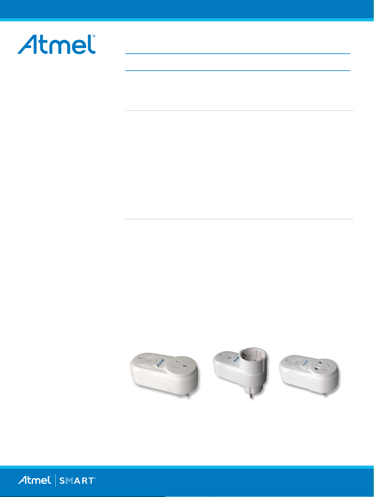
Three models following either US, EU, or Chinese standards
AC input 90-265V and 50/60Hz
Max output power: 2200W(10A)
Based on ATSAMW25 module
– ATSAMD21 Cortex-M0+ MCUWINC1500 IEEE 802.11 b/g/n 2.4G Wi-Fi
Controller
– ECC508A hardware Authentication and Encryption
ATM90E26 power and energy metering function
QTouch button
CE/FCC/UL&CUL Certification
Figure 1. Atmel Smart Plug Kits

2
2
Table of Contents
1 Overview ..................................................................................................................... 3
1.1 System Overview .................................................................................................................................. 3
2 MCU Board ................................................................................................................... 4
2.1 MCU Board Overview ............................................................................................................................ 4
2.2 ATSAMW25 .......................................................................................................................................... 5
2.3 Programming Interface .......................................................................................................................... 7
2.4 Header to Touch Board ......................................................................................................................... 7
2.5 Header to Power Board ......................................................................................................................... 8
2.6 DataFlash (Not Mounted) ...................................................................................................................... 8
3 Touch Board ................................................................................................ ................ 9
3.1 Touch Board Overview .......................................................................................................................... 9
3.2 Touch Sensors ...................................................................................................................................... 9
3.3 LEDs for Wi-Fi and Power ................................................................................................................... 10
3.3.1 Wi-Fi LED ............................................................................................................................... 10
3.3.2 Power LED ............................................................................................................................. 10
3.3.3 LED Pin Definition on SAM W25 ............................................................................................ 10
4 Power Board ................................................................................................ .............. 10
4.1 Power Board Overview ........................................................................................................................ 10
4.2 AC-DC .............................................................................................................................................. 11
4.3 The Fuse ............................................................................................................................................. 12
4.4 DC-DC .............................................................................................................................................. 12
4.5 Power Measurement ........................................................................................................................... 12
4.6 Power Measurement Calibration ......................................................................................................... 14
4.6.1 Calculation of the GL .............................................................................................................. 14
4.6.2 Calculation of the Ugain.......................................................................................................... 14
4.6.3 Calculation of the Igain ................................ ........................................................................... 14
4.6.4 Calculation of the PL_Constant .............................................................................................. 14
4.7 The Relay ............................................................................................................................................ 14
4.8 Plug and Socket .................................................................................................................................. 15
5 PCB Assembly ........................................................................................................... 17
5.1 PCB Stack Structure ........................................................................................................................... 17
6 Reprogram the Kit ..................................................................................................... 18
6.1 Open the Kit ........................................................................................................................................ 18
6.2 Power Supply ...................................................................................................................................... 18
6.2.1 Onboard AC Power ................................................................................................................ 18
6.2.2 External DC power ................................................................................................................. 19
6.3 Programming Tools ............................................................................................................................. 20
6.4 Programming ....................................................................................................................................... 21
7 Revision History ........................................................................................................ 22
AT16225: Atmel Smart Plug Hardware User Guide [APPLICATION NOTE]
Atmel-42689B-Atmel-Smart-Plug-Hardware-User-Guide_AT16225_ApplicationNote_07/2016
3
3
ATSAMW25
Output Socket
AC/DC
3.3V
DC/DC
LEDs
12V
L
N
Button
Relay
Fuse
Input Plug
DataFlash
E
ATM90E26
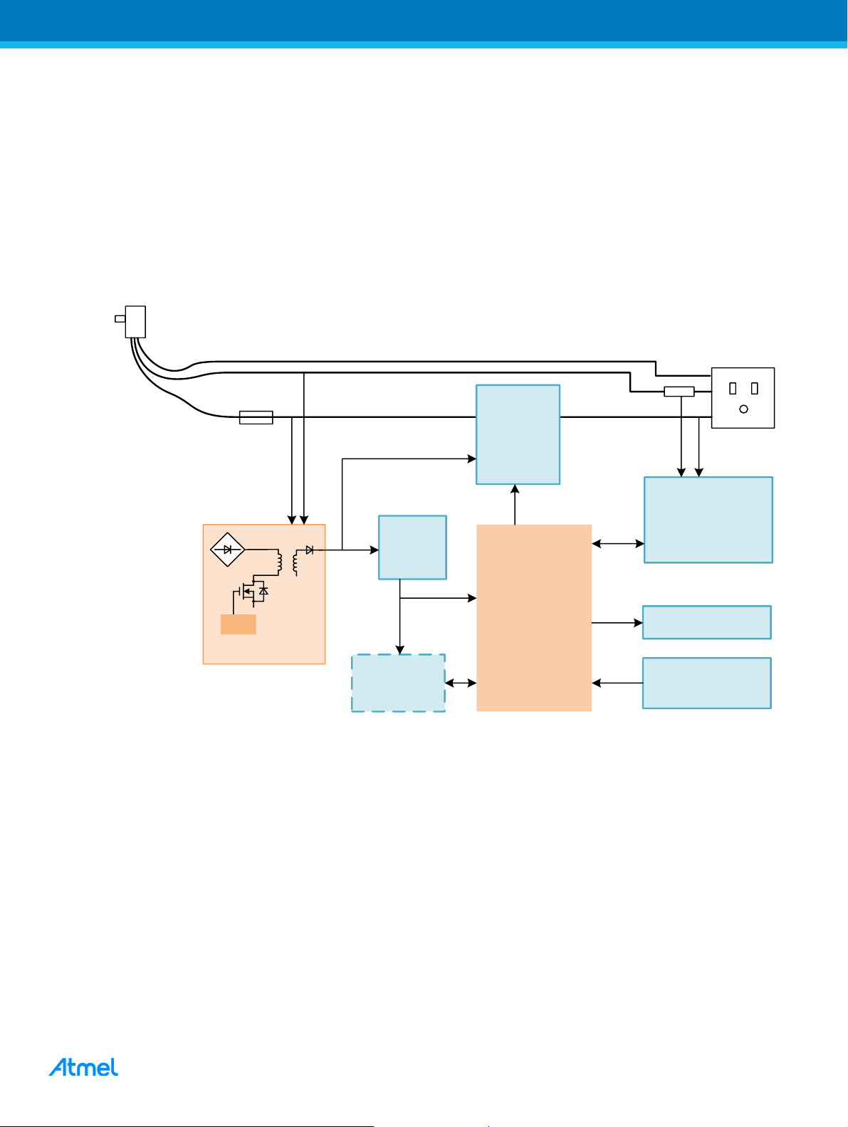
1 Overview
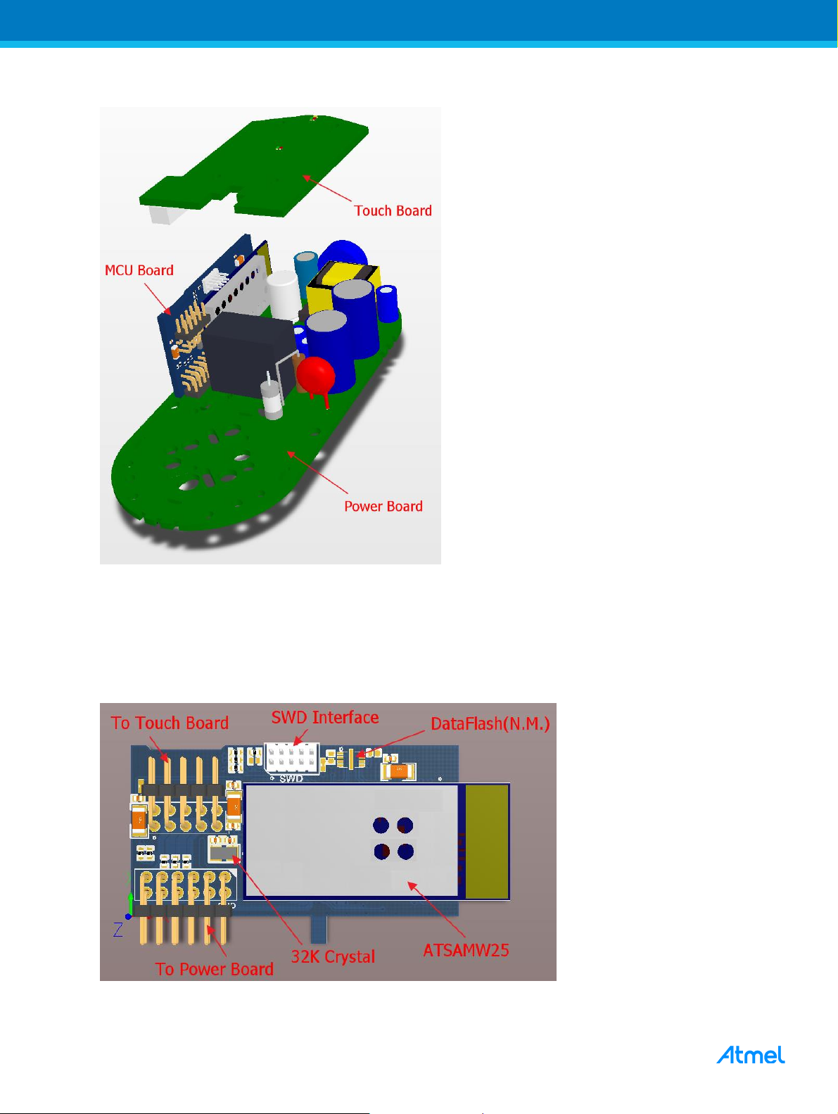
The smart plug consists of three PCBs: Power board, MCU board, and Touch board. The MCU board is
vertically mounted to the Power board and the Touch board is connected to the MCU board by a pin connector.
Touch Board: Touch pad and LEDs.
MCU Board: ATSAMW25, 32KHz crystal, DataFlash footprint (not mounted).
Power Board: Socket and Plug, AC-DC, DC-DC, Power Measurement, Relay.
1.1 System Overview
Figure 1-1. System Block Diagram
AT16225: Atmel Smart Plug Hardware User Guide [APPLICATION NOTE]
Atmel-42689B-Atmel-Smart-Plug-Hardware-User-Guide_AT16225_ApplicationNote_07/2016
4
4
Figure 1-2. Overview of the Smart Plug Kit PCBs
2 MCU Board
2.1 MCU Board Overview
Figure 2-1. MCU Board Overview
AT16225: Atmel Smart Plug Hardware User Guide [APPLICATION NOTE]
Atmel-42689B-Atmel-Smart-Plug-Hardware-User-Guide_AT16225_ApplicationNote_07/2016
5
5
Pin #
SAM W25 function
System function
Description
0
GND
GND
Heat sink pads in the bottom
1
GND
GND
2 UART TXD
Wi-Fi TXD
For ATWINC1500 firmware upgrade
3
UART RXD
Wi-Fi RXD
For ATWINC1500 firmware upgrade
4
Wi-Fi Chip En
NC
5
Wi-Fi GPIO_1
RTC
Not Used
6
NC
NC
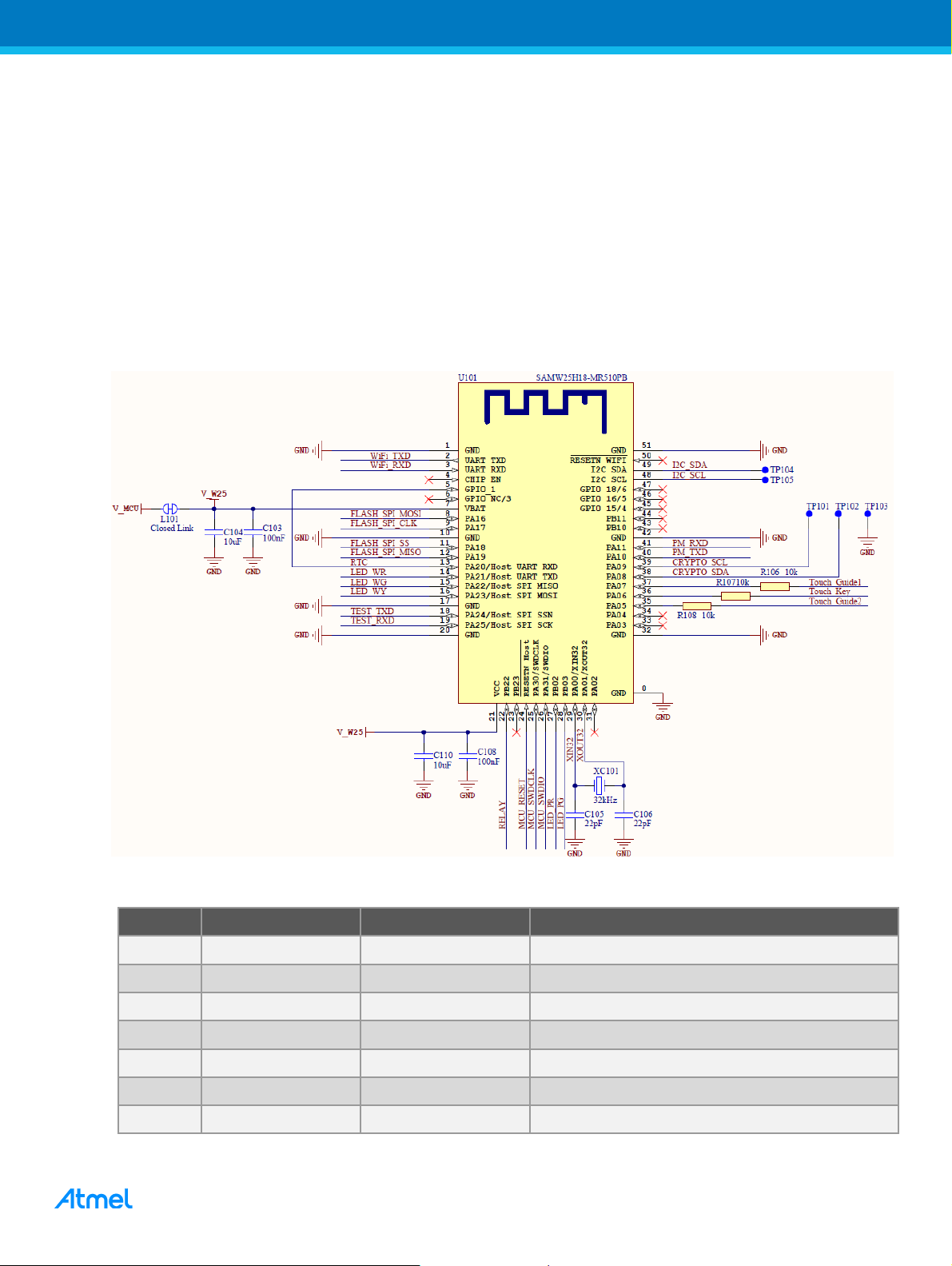
2.2 ATSAMW25
The Atmel SmartConnect SAM W25 is a low-power Wi-Fi certified module. This highly integrated module offers
the ideal solution for designers seeking Wi-Fi connectivity. The SAM W25 integrates an 802.11 IP stack on top
of the Wi-Fi core and fully covers RF certifications.
The SAM W25 module is based on Atmel’s industry-leading WINC1500 Wi-Fi core combined with Atmel’s
latest ARM Cortex-M0+ based microcontroller (SAM D21) technology. This turnkey system provides an
integrated software solution with application and security protocols such as TLS and integrated network
services (TCP/IP stack).
ATSAMW25 is the control center of the smart plug kit. It covers all the intelligent functions including the Wi-Fi
connection, touch button, relay control, temperature sensing and protection, LED indicators, and timing.
Figure 2-2. Schematic for ATSAMW25
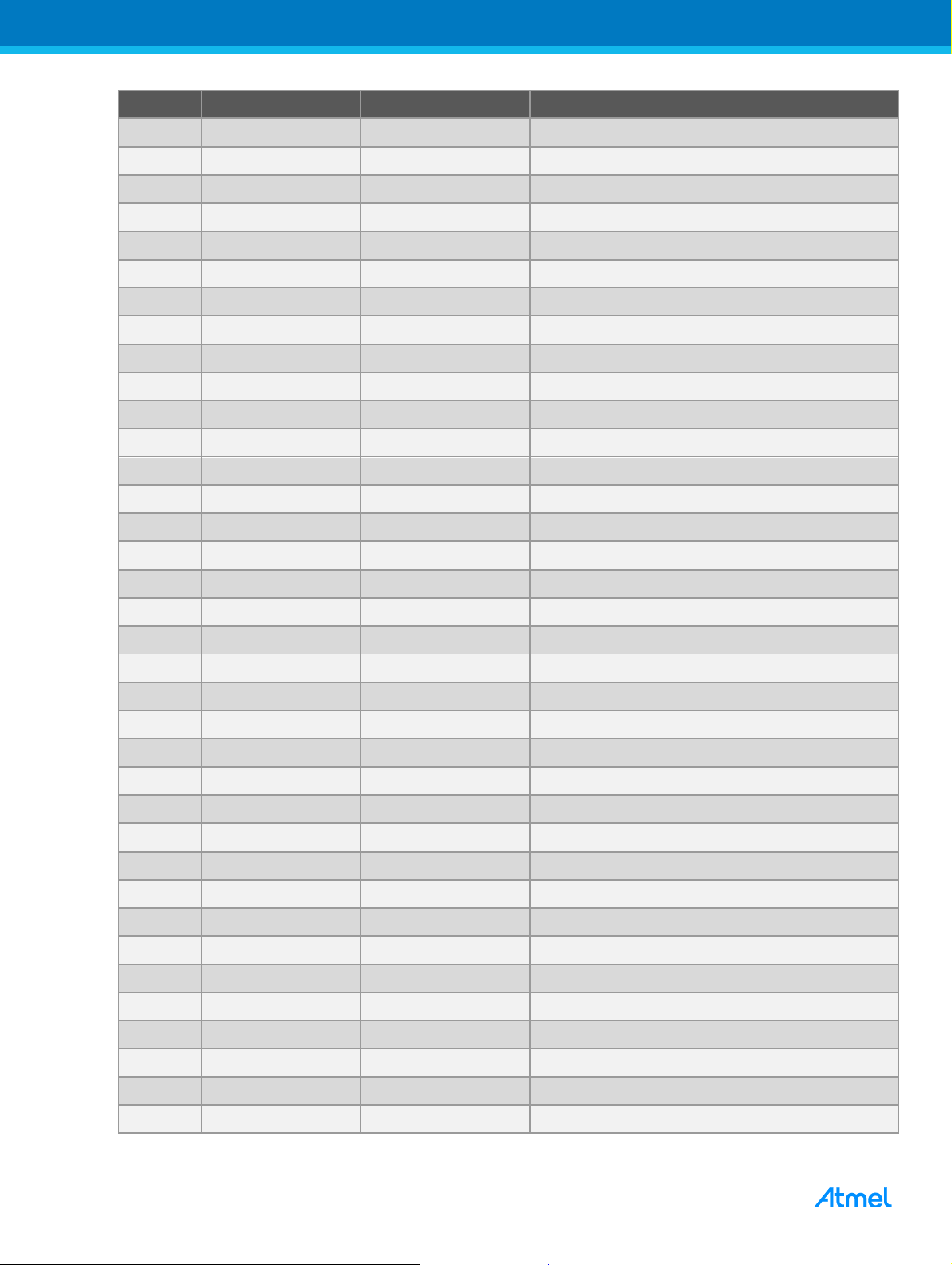
Table 2-1. ATSAMW25 Pinout
AT16225: Atmel Smart Plug Hardware User Guide [APPLICATION NOTE]
Atmel-42689B-Atmel-Smart-Plug-Hardware-User-Guide_AT16225_ApplicationNote_07/2016
6
6
Pin #
SAM W25 function
System function
Description
7
VBAT
VCC
Power supply
8
PA16
Flash SPI MOSI
DataFlash Interface
9
PA17
Flash SPI CLK
DataFlash Interface
10
GND
GND
11
PA18
Flash SPI SS
DataFlash Interface
12
PA19
Flash SPI MISO
DataFlash Interface
13
PA20
RTC
Not Used
14
PA21
LED WR
Red LED for Wi-Fi
15
PA22
LED WG
Green LED for Wi-Fi
16
PA23
LED WY
Yellow LED for Wi-Fi
17
GND
GND
18
PA24
Test TXD
Fixture test interface
19
PA25
Test RXD
Fixture test interface
20
GND
GND
21
VCC
VCC
Power supply
22
PB22
Relay
Relay ON/OFF
23
PB23
NC 24
RESET_N
MCU Reset
SAM D21 reset pin
25
PA30
MCU SWDCLK
SWD SWDCLK pin
26
PA31
MCU SWDIO
SWD SWDCLK pin
27
PB02
LED PR
Red LED for Power
28
PB03
LED PG
Green LED for Power
29
PA00
XIN32
32kHz External Crystal
30
PA01
XOUT32
32kHz External Crystal
31
PA02
NC
32
GND
GND
33
PA03
NC 34
PA04
NC 35
PA05
Touch Guard 2
Touch Guard sensor
36
PA06
Touch Key
Touch key sensor
37
PA07
Touch Guard 1
Touch Guard sensor
38
PA08
Crypto SDA
Reserved interface for internal crypto
39
PA09
Crypto SCL
Reserved interface for internal crypto
40
PA10
PM TXD
Interface for Power Measurement device
41
PA11
PM RXD
Interface for Power Measurement device
42
GND
GND
AT16225: Atmel Smart Plug Hardware User Guide [APPLICATION NOTE]
Atmel-42689B-Atmel-Smart-Plug-Hardware-User-Guide_AT16225_ApplicationNote_07/2016
7
7
Pin #
SAM W25 function
System function
Description
43
PB10
NC 44
PB11
NC 45
Wi-Fi GPIO_15
NC 46
Wi-Fi GPIO_16
NC 47
Wi-Fi GPIO_18
NC 48
Wi-Fi I2C SCL
I2C SCL
Reserved interface for internal WINC1500
49
Wi-Fi I2C SDA
I2C SDA
Reserved interface for internal WINC1500
50
Wi-Fi Reset_n
NC 51
GND
GND
SWD header pin
Pin definition
ATSAMW25 pin
1
SWDCLK
25
2
GND
3
NC 4
VCC
5 SWDIO
26 6 RESET
24 7 NC 8
NC 9
NC 10
NC
Touch header pin
Pin definition
ATSAMW25 pin
1
GND (External power input if onboard power is not available)
2 VCC (External power input if onboard power is not available)
3
Touch Guard Sensor 1
37
4
Power LED Green
28 5 Touch Key Sensor
36
2.3 Programming Interface
Since SAM W25 uses the SAM D21 as the controller, the user can use the SWD interface to Program and
debug the device.
Table 2-2. Pin Definition of SWD Interface
2.4 Header to Touch Board
The Touch Board is connected to MCU Board through a 10-pin header, it contains the tracks for the touch
sensors and LEDs. The header also makes it possible to power the MCU externally.
Table 2-3. Header to Touch Board
AT16225: Atmel Smart Plug Hardware User Guide [APPLICATION NOTE]
Atmel-42689B-Atmel-Smart-Plug-Hardware-User-Guide_AT16225_ApplicationNote_07/2016
8
8
6
Power LED Red
27
7
Touch Guard Sensor 2
35 8 Wi-Fi LED Red
14 9 Wi-Fi LED Yellow
16
10
Wi-Fi LED Green
15
Power header pin
Pin definition
ATSAMW25 pin
1
VCC
2
GND
3
Wi-Fi TXD (Reserved for Wi-Fi firmware upgrade on fixture)
2
4
Wi-Fi RXD (Reserved for Wi-Fi firmware upgrade on fixture)
3 5 Test RXD (Reserved for fixture)
19
6
Test TXD (Reserved for fixture)
18
7
Power Measurement RXD (Interface for MCU and power measurement
device)
41
8
Power Measurement TXD (Interface for MCU and power measurement
device)
40
9
MCU Reset (Reserved for fixture)
24
10
Relay Control
22
11
MCU SWDIO (Reserved for fixture)
26
12
MCU SWDCLK (Reserved for fixture)
25
2.5 Header to Power Board
The MCU Board is mounted directly on the Power Board by a 12-pin header.
Table 2-4. Header to Power Board
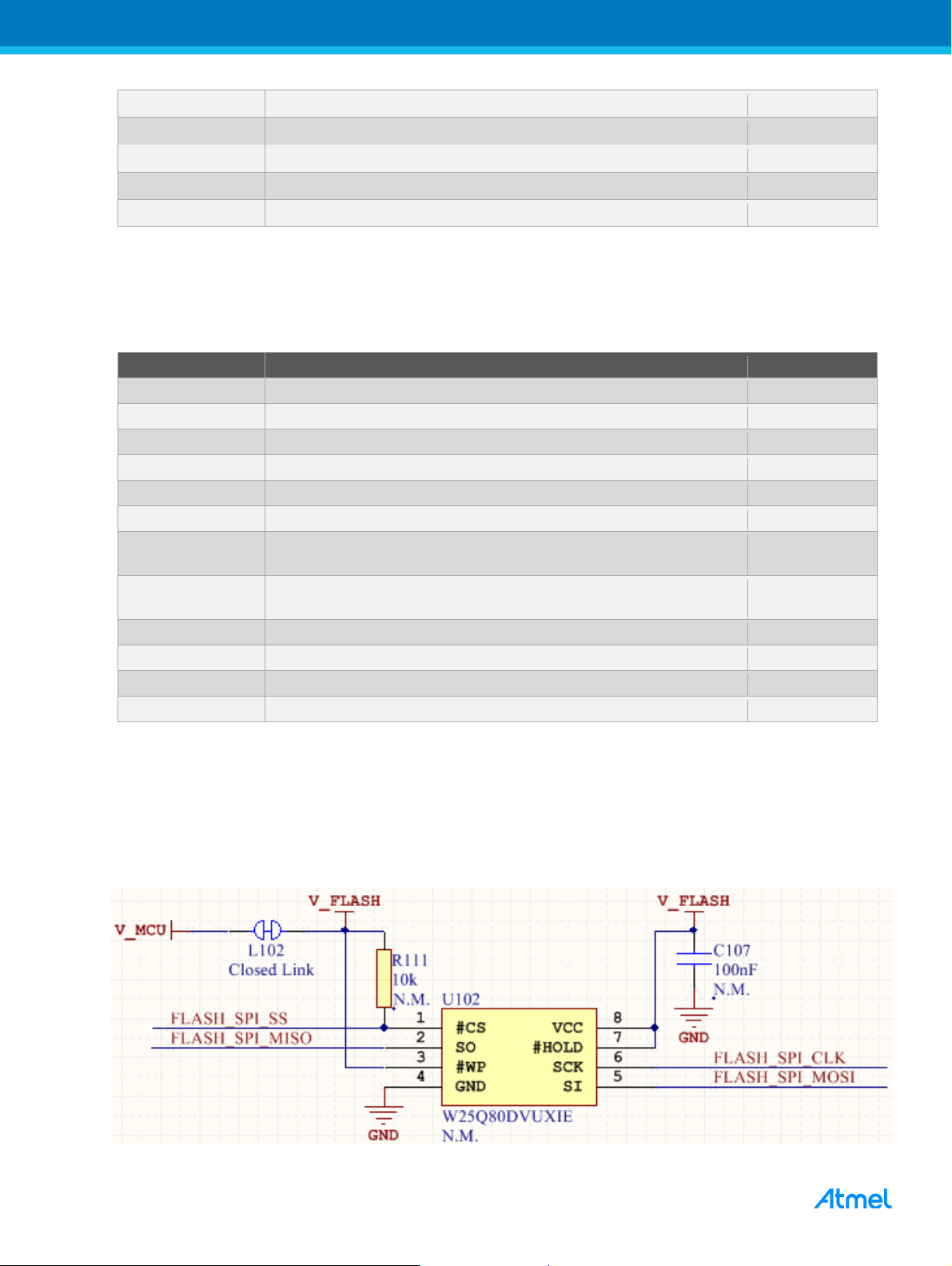
2.6 DataFlash (Not Mounted)
Space for a DataFlash device is reserved (but not mounted) on the board. This can be used to store more data
locally if needed.
Figure 2-3. Schematic of DataFlash Part
AT16225: Atmel Smart Plug Hardware User Guide [APPLICATION NOTE]
Atmel-42689B-Atmel-Smart-Plug-Hardware-User-Guide_AT16225_ApplicationNote_07/2016

9
9
Designator
Value
Vendor
Part Number
Description
C107
100nF
Murata
GRM155R71H104KE14
Ceramic capacitor, SMD 0402, X7R, 50V, 10%
R111
10k
Yageo
RC0402FR-0710KL
Thick film resistor, SMD 0402, 1/16W, 1%
U102
1M Byte
Winbond
W25Q80DVUXIE
Serial Flash, 8-lead USON 2*3mm
Pin name on DataFlash
Pin name on ATSAMW25
ATSAMW25 pin
FLASH_SPI_SS
PA18
11
FLASH_SPI_MISO
PA19
12
FLASH_SPI_MOSI
PA16
8
FLASH_SPI_CLK
PA17
9
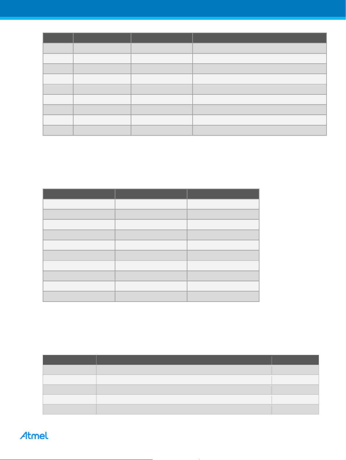
Table 2-5. BoM for the DataFlash Part if Mounted
Table below shows the pin definition of SAM W25 for DataFlash.
Table 2-6. Pin Definition of DataFlash and SAM W25
3 Touch Board
3.1 Touch Board Overview
The Touch board contains the Touch sensors and the LEDs for Wi-Fi and Power.
Figure 3-1. Touch Board Overview
3.2 Touch Sensors
Touch sensors are designed based on the self-capacitor using the QTouch technology.
Except the Touch Key which handles the ON/OFF/Reset function, another two touch sensors act as the touch
guard. The touch guard sensors will prevent some scenarios from spurious triggering.
AT16225: Atmel Smart Plug Hardware User Guide [APPLICATION NOTE]
Atmel-42689B-Atmel-Smart-Plug-Hardware-User-Guide_AT16225_ApplicationNote_07/2016

1
10
Pad name on touch board
Pin name on ATSAMW25
ATSAMW25 pin
Touch Key
PA06
36
Touch Guard 1
PA07
37
Touch Guard 2
PA05
35
LED name on touch board
Active logic
Pin name on ATSAMW25
ATSAMW25 pin
Wi-Fi Yellow
1
PA23
16
Wi-Fi Green
1
PA22
15
Wi-Fi Red
1
PA21
14
Power Green
1
PB03
28
Power Red
1
PB02
27
Table 3-1. Pin definition of Touch Sensor and SAM W25
3.3 LEDs for Wi-Fi and Power
All LEDs including the Wi-Fi and Power LEDs are driven by the ATSAMW25 GPIOs directly, Logic 1 enables
the LEDs.
Note: For better output current performance, the I/O pins needs be set to high drive strength: DRVSTR = 1.
Different color LEDs are used to indicate different status of the plug.
3.3.1 Wi-Fi LED
Yellow blink: Plug in SoftAP mode, not connected (waiting for Phone to connect)
Yellow: Plug in SoftAP mode, connected to a phone (during this period, Phone App sends
SSID/password to plug)
Green blink: Plug in STA mode, connecting to home Access Point (AP)
Green: Plug in STA mode, connected to home AP, connection is good
Red: In error state
3.3.2 Power LED
Green when ON
Red when OFF
3.3.3 LED Pin Definition on SAM W25
Table 3-2. Pin Definition of LEDs and SAM W25
4 Power Board
4.1 Power Board Overview
The Power Board contains an AC-DC converter, a DC-DC converter, the power measurement circuit, relay,
and the plug and socket.
AT16225: Atmel Smart Plug Hardware User Guide [APPLICATION NOTE]
Atmel-42689B-Atmel-Smart-Plug-Hardware-User-Guide_AT16225_ApplicationNote_07/2016

1
11
Figure 4-1. Power Board Overview
4.2 AC-DC
The AC-DC part transforms the 100V~240V AC input voltage into a 12V/120mA (typical) DC output.
The 12V DC supplies the relay and the DC-DC converter.
Figure 4-2. Schematic of AC-DC Part
AT16225: Atmel Smart Plug Hardware User Guide [APPLICATION NOTE]
Atmel-42689B-Atmel-Smart-Plug-Hardware-User-Guide_AT16225_ApplicationNote_07/2016

1
12
Wire
Type
Start to end
Turns
Tape
N1
2UEW Φ 0.15x1P
3-1
70Ts
1Ts
N2
2UEW Φ 0.15x1P
4-5
23Ts
2Ts
N4
TRWB Φ 0.35x1P
7-6
24Ts
3Ts
The transformer T301 is a custom component with the parameters below.
Figure 4-3. Transformer Design
Table 4-1. Wire Definition of Transformer
4.3 The Fuse
If broken, the fuse F301 (12A) should be changed by the professional person.
4.4 DC-DC
The DC-DC converter converts the DC voltage level from 12V to 3.3V for the SAM W25 module. The MP1470
is a typical buck DC-DC converter, with the output range set to 3.16V to 3.36V.
Figure 4-4. Schematic of DC-DC Part
4.5 Power Measurement
The ATM90E26 works as the power measurement device to get the actual output power.
There are two signals sampled by ATM90E26, one is the voltage which comes from the L line, another is the
differential voltage based on the current in sense resistor R311.
AT16225: Atmel Smart Plug Hardware User Guide [APPLICATION NOTE]
Atmel-42689B-Atmel-Smart-Plug-Hardware-User-Guide_AT16225_ApplicationNote_07/2016

1
13
Figure 4-5. Sampled Signal of Power Measurement
The power measurement device will calculate and output the sampled voltage, current, and power to SAM
W25 through the UART port. Considering the different power supply system, 2 optocouplers are used to isolate
the SAM W25 and M90E26.
Figure 4-6. Schematic of Power Measurement
AT16225: Atmel Smart Plug Hardware User Guide [APPLICATION NOTE]
Atmel-42689B-Atmel-Smart-Plug-Hardware-User-Guide_AT16225_ApplicationNote_07/2016

1
14
Pin Name for Uart
Pin name on ATSAMW25
ATSAMW25 pin
PWR_PM_TXD
PA10
40
PWR_PM_RXD
PA11
41
Table 4-2. Pin Definition of Power Measurement and SAM W25
4.6 Power Measurement Calibration
Before using the ATM90E26 in user application, some parameters need be calculated, such as GL, Ugain,
Igain, and PL_Contant.
MC: Pulse constant of the energy meter, unit is imp/kWh or imp/kvarh; Assume MC = 10000
Un: Reference voltage, unit is V; Assume Un = 220V
Ib: Basic current, unit is A; Assume Ib = 1A
GL: L line current circuit gain
VL: Sampling voltage of the L line circuit at Ib, unit is mV
VU: Sampling voltage of the voltage circuit at Un, unit is mV
4.6.1 Calculation of the GL
With the shunt resistor = 1mΩ, Max. current I = 10A.
When, GL = 24
VLsample = 1mΩ * 10A * 24 = 240mV
4.6.2 Calculation of the Ugain
The default Ugain is based on the condition below:
Ugain = 26400 (6720H), Voltage divider coefficient = 880,
Assume Un = 220V, VL = 220 / (880 + 1)
Considering the voltage divider resistors used in smart plug, Voltage divider coefficient = (430 + 430) = 860
So, Ugain = 26400 * (220 / (860 + 1)) / (220 / (880 + 1)) = 27013 (6985H)
4.6.3 Calculation of the Igain
From AN 46102,
R = 200µΩ, I = 5A, Lgain = 24 <=> Igain = 31251 (7A13H) by default
In SmartPlug solution,
R = 1mΩ, I = 2A, Lgain = 24 <=> Igain = 31251 * (1000 * 2A * 24) / (200 * 10A * 24) = 62502 (F426H)
4.6.4 Calculation of the PL_Constant
PL_Constant = int (838860800 * GL * VL * Vu / MC * Un * Ib)
= 838860800 * 24 * 1 * (220 / (860 + 1)) / 10000 * 220 * 1 = 2338287(23ADEFH)
4.7 The Relay
The relay is cascaded in the AC input and output. So, the Relay can direct control the ON/OFF of the AC
output.
The rated current of the relay is 10A, this means the output power is limited to Max 2200W (@ 220V AC).
AT16225: Atmel Smart Plug Hardware User Guide [APPLICATION NOTE]
Atmel-42689B-Atmel-Smart-Plug-Hardware-User-Guide_AT16225_ApplicationNote_07/2016

1
15
Relay Contorl Name
Active Logic
Pin name on ATSAMW25
ATSAMW25 pin
PWR_RELAY
1
PB22
22
Note: Some electronic devices may generate a surge current far larger than the rated current; damaging the
relay by welding the contact shut. When this happens the output will be always ON and the kit will be
out of control. If this happens you must cut the input voltage manually immediately. From testing it has
been observed that a surge current of bigger than 50A can make the contactor adhere.
Figure 4-7. Schematic of Relay Control
Table 4-3. Pin Definition of Relay
4.8 Plug and Socket
There are three types of the Plug and Socket: US, EU, and CN. They share the same PCB.
AT16225: Atmel Smart Plug Hardware User Guide [APPLICATION NOTE]
Atmel-42689B-Atmel-Smart-Plug-Hardware-User-Guide_AT16225_ApplicationNote_07/2016

1
16
Figure 4-8. US, EU, and CN standard of Plug and Socket
AT16225: Atmel Smart Plug Hardware User Guide [APPLICATION NOTE]
Atmel-42689B-Atmel-Smart-Plug-Hardware-User-Guide_AT16225_ApplicationNote_07/2016

1
17
5 PCB Assembly
5.1 PCB Stack Structure
The touch board is assembled in the front case of the kit, and the power board together with the MCU board is
fixed in the rear case.
When the front and rear case are closed, make sure the touch board connector is aligned with the MCU board
pin header.
Figure 5-1. PCB Stack Structure Overview
AT16225: Atmel Smart Plug Hardware User Guide [APPLICATION NOTE]
Atmel-42689B-Atmel-Smart-Plug-Hardware-User-Guide_AT16225_ApplicationNote_07/2016

1
18
6 Reprogram the Kit
6.1 Open the Kit
If the user needs to reprogram the kit with custom code, the kit needs be opened first.
Figure 6-1. Remove the Silica Gel and Screws
Figure 6-2. Open the Kit
6.2 Power Supply
There are two methods to power the Kit while reprogramming: Onboard AC power and external DC power.
6.2.1 Onboard AC Power
At first, connect the programming tools and Kit with the 10-pin SWD connector.
Then, plug the Kit into the AC socket and the kit will be powered by the onboard power supply.
AT16225: Atmel Smart Plug Hardware User Guide [APPLICATION NOTE]
Atmel-42689B-Atmel-Smart-Plug-Hardware-User-Guide_AT16225_ApplicationNote_07/2016

1
19
After programming, the user needs to remove the kit from the AC socket first and then disconnect the
programmer/debugger from the SWD header.
Note: The user needs be very carefully during operation and avoid touching any of the components since
they are not isolated and can easily lead to an electrical shock.
Figure 6-3. Kit Powered by the Onboard AC Input
6.2.2 External DC power
As described in the MCU board chapter, the kit can also be powered by an external 3.3VDC supply.
Before connecting the 3.3VC, the user needs to make sure the kit is not connected to the AC input.
Connect the 3.3V power supply on pin1 and pin2 of Touch header and make sure the polarity is correct.
Note: It is recommended to use the external DC to power the board while reprogramming since it is far safer
than the AC power.
Figure 6-4. Kit Powered by the External DC Input
AT16225: Atmel Smart Plug Hardware User Guide [APPLICATION NOTE]
Atmel-42689B-Atmel-Smart-Plug-Hardware-User-Guide_AT16225_ApplicationNote_07/2016

2
20
Figure 6-5. External Power Input
Note: The Power Pins in on the touch header is connected in parallel with the power supply (3.3V) on the
power board. Never connect an external power supply while the onboard power is available.
6.3 Programming Tools
The smart plug uses the SWD as the programming and debug\interface, it supports all tools which supports the
SWD interface. Some tools support a direct connection with the 1.27mm pitch, 10-pin socket. Figures below
show the connection example of programming tools.
Figure 6-6. Atmel-ICE Connection
Figure 6-7. JTAGICE3 Connection
AT16225: Atmel Smart Plug Hardware User Guide [APPLICATION NOTE]
Atmel-42689B-Atmel-Smart-Plug-Hardware-User-Guide_AT16225_ApplicationNote_07/2016

2
21
For other programming tools which do not have the 1.27mm pitch, 10-pin socket, the user needs to connect the
SWD lines manually.
6.4 Programming
Connect the kit to a PC with Atmel Studio installed.
Click Tools → Device Programming to open the programming dialog. Then, program the kit as show below.
Note: The Device selector must be set to ATSAMD21G18A.
Figure 6-8. Reprogramming Flow by Atmel Studio
Programming steps:
1. Select the programming tool.
2. Choose device (must be ATSAMD21G18A) and select the interface (must be SWD).
3. Apply the setting.
4. To ensure the correct connection, press ‘Read’ to get the device signature and target voltage.
5. Browse to the folder where the code located, and select it.
6. Program the device. The status can be displayed in the information frame below.
AT16225: Atmel Smart Plug Hardware User Guide [APPLICATION NOTE]
Atmel-42689B-Atmel-Smart-Plug-Hardware-User-Guide_AT16225_ApplicationNote_07/2016

2
22
Doc Rev.
Date
Comments
42698B
07/2016
A new section 4.3 (The Fuse) is added.
In section 4.7, the “Note”. “less than” has been corrected to “bigger than”.
42689A
03/2016
Initial document release.
7 Revision History
AT16225: Atmel Smart Plug Hardware User Guide [APPLICATION NOTE]
Atmel-42689B-Atmel-Smart-Plug-Hardware-User-Guide_AT16225_ApplicationNote_07/2016

2
23
Atmel Corporation 1600 Technology Drive, San Jose, CA 95110 USA T: (+1)(408) 441.0311 F: (+1)(408) 436.4200 │ www.atmel.com
© 2016 Atmel Corporation. / Rev.: Atmel-42689B-Atmel-Smart-Plug-Hardware-User-Guide_AT16225_ApplicationNote_07/2016.
Atmel®, Atmel logo and combinations thereof, Enabling Unlimited Possibilities®, QTouch®, and others are registered trademarks or trademarks of Atmel Corporation
in U.S. and other countries. ARM®, ARM Connected® logo, and others are the registered trademarks or trademarks of ARM Ltd. Other terms and product names may
be trademarks of others.
DISCLAIMER: The information in this document is provided in connection with Atmel products. No license, express or implied, by estoppel or otherwise, to any intellectual property right
is granted by this document or in connection with the sale of Atmel products. EXCEPT AS SET FORTH IN THE ATMEL TERMS AND CONDITIONS OF SALES LOCATED ON THE
ATMEL WEBSITE, ATMEL ASSUMES NO LIABILITY WHATSOEVER AND DISCLAIMS ANY EXPRESS, IMPLIED OR STATUTORY WARRANTY RELATING TO ITS PRODUCTS
INCLUDING, BUT NOT LIMITED TO, THE IMPLIED WARRANTY OF MERCHANTABILITY, FITNESS FOR A PARTICULAR PURPOSE, OR NON-INFRINGEMENT. IN NO EVENT
SHALL ATMEL BE LIABLE FOR ANY DIRECT, INDIRECT, CONSEQUENTIAL, PUNITIVE, SPECIAL OR INCIDENTAL DAMAGES (INCLUDING, WITHOUT LIMITATION, DAMAGES
FOR LOSS AND PROFITS, BUSINESS INTERRUPTION, OR LOSS OF INFORMATION) ARISING OUT OF THE USE OR INABILITY TO USE THIS DOCUMENT, EVEN IF ATMEL
HAS BEEN ADVISED OF THE POSSIBILITY OF SUCH DAMAGES. Atmel makes no representations or warranties with respect to the accuracy or completeness of the contents of this
document and reserves the right to make changes to specifications and products descriptions at any time without notice. Atmel does not make any commitment to update the information
contained herein. Unless specifically provided otherwise, Atmel products are not suitable for, and shall not be used in, automotive applications. Atmel products are not intended,
authorized, or warranted for use as components in applications intended to support or sustai n life.
SAFETY-CRITICAL, MILITARY, AND AUTOMOTIVE APPLICATIONS DISCLAIMER: Atmel products are not designed for and will not be used in connection with any applications where
the failure of such products would reasonably be expected to result in significant personal injury or death (“Sa fety-Cr itical Appl ications”) without an At mel officer's specific written conse nt.
Safety-Critical Applications include, without limitation, life support devices and systems, equipment or systems for the operation of nuclear facilities and weapons systems. Atmel
products are not designed nor intended for use in military or aerospace applications or environments unless specifically designated by Atmel as military-grade. Atmel products are not
designed nor intended for use in automotive applications unless specifically designated by Atmel as automotive-grade.
AT16225: Atmel Smart Plug Hardware User Guide [APPLICATION NOTE]
Atmel-42689B-Atmel-Smart-Plug-Hardware-User-Guide_AT16225_ApplicationNote_07/2016

Mouser Electronics
Authorized Distributor
Click to View Pricing, Inventory, Delivery & Lifecycle Information:
Microchip:
ATSMARTPLUGUS ATSMARTPLUGEU ATSMARTPLUGCN ATSMARTPLUG-CN ATSMARTPLUG-US
ATSMARTPLUG-EU
 Loading...