

TBDA-MCU-09/2013
USER GUIDE
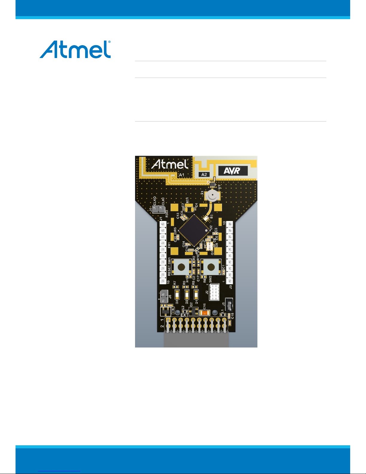
AT04357 RCB256RFR2-XPRO User Guide
Introduction
This application note describes how to get started with the Atmel®
RCB256RFR2-XPRO Extension board.
The Extension boards is targeted for evaluating the features of the Atmel
ATmega256RFR2 wireless SoC with PCB antenna.

AT04357 RCB256RFR2-XPRO User Guide [USER GUIDE]
TBDA-MCU-09/2013
2
Table of Contents
Introduction .................................................................................... 1
1. Getting Started ........................................................................ 3
1.1. Features ..... ..... ....................... ..... ..... ..... ..... .................. ..... .. 3
1.2. Design documentation and related links ..... ..... ..... ..... ..... ..... ....... 3
1.3. Board Assembly . ..... ..... ..... ....................... ..... ..... ..... ..... ......... 3
1.3.1. Connect to a Xplained PRO board .... ..... ..... ..... ..... ....... 3
1.3.2. Standalone node ................... ..... ..... ..... ..... ................ 3
1.3.3. In customer development assembly . ..... ..... .................. . 3
1.4. Connecting the kit ............ ..... ..... ..... ..... ....................... ..... ..... 3
1.4.1. Atmel Studio ........... ..... ..... ..... ..... ....................... ..... . 4
1.4.2. Connect the extension UART to the EBDG COM port .... ... 4
1.5. Programming .................. ..... ..... ..... ..... .................. ..... ..... ..... . 4
1.5.1. JTAGICE .... ..... ..... ..... ..... .................. ..... ..... ..... ..... ... 4
1.5.2. Boot loader ..................... ..... ..... ..... ..... .................. ... 4
1.6. Available example code ............. ..... ..... ..... ..... ....................... .. 5
2. Performance Analyzer ............................................................. 6
2.1. Introduction ....................... ..... ..... ..... ..... .................. ..... ..... ... 6
2.2. Program installation .............. ..... ..... ..... ..... ..... .................. ..... . 6
2.3. Program use ..................... ..... ..... ..... ..... ....................... ..... ... 9
3. Xplained Pro .......................................................................... 11
3.1. Hardware identification system . ..... ..... ..... ..... ....................... ... 11
3.2. Standard headers and connectors ..... .................. ..... ..... ..... .... 11
3.2.1. Xplained Pro standard extension header .... ..... ..... ........ 11
4. Hardware user guide ............................................................ 13
4.1. Board overview . ..... ..... ..... ....................... ..... ..... ..... ..... ........ 13
4.2. Headers and connectors .................. ..... ..... ..... ..... ..... ............ 13
4.2.1. J100 Xplained Pro extension connector ......... ..... ..... .... 13
4.2.2. J1 & J3 ........... ..... ..... ..... ..... ....................... ..... ..... . 14
4.2.3. JTAG (J2) .. ..... ..... ..... ....................... ..... ..... ..... ..... .. 14
4.2.4. CLK (J4) ... ..... ....................... ..... ..... ..... ..... ............. 15
4.2.5. Current monitoring (J5) ... ..... ..... ..... ....................... .... 15
4.2.6. External power (J6) ..... ..... ..... ..... .................. ..... ..... . 15
4.3. Board GUI ... ..... .................. ..... ..... ..... ..... ....................... ..... 16
4.3.1. LED's ..... ..... ..... .................. ..... ..... ..... ..... ............... 16
4.3.2. Button ..... ..... ....................... ..... ..... ..... ..... .............. 16
4.4. Factory programmed data ........ ..... ..... ..... ..... .................. ..... .. 16
5. Agency Certifications ............................................................ 17
5.1. United State (FCC) .. ..... ..... .................. ..... ..... ..... ..... ............ 17
5.2. European Union (ETSI) ..... ..... ....................... ..... ..... ..... ..... ... 17
5.3. Canada (IC) ................ ..... ..... ..... ..... ....................... ..... ..... .. 18
5.4. Using Limited Modular Certified Products ... ..... ..... ..... ..... .......... 18
6. Document revision history ..................................................... 20

AT04357 RCB256RFR2-XPRO User Guide [USER GUIDE]
TBDA-MCU-09/2013
3
1. Getting Started
1.1 Features
The RCB256RFR2-XPRO extension board provide a development/prototype platform for the Atmel
ATmega256RFR2.
1.2 Design documentation and related links
The following list contains links to the most relevant documents and software for the extension boards.
http://www.atmel.com/tools/rcb256rfr2-xpro.aspx
1.3 Board Assembly
The extension board can be used in number of combinations. To provide wireless communication to a Xplained
PRO board, to act as a standalone wireless node, to provide wireless communication to your own prototype for
SW development and HW verification.
1.3.1 Connect to a Xplained PRO board
The Extension board can be connected to any Xplained PRO main board using the extension header.
Picture of SAM4L with extension
1.3.2 Standalone node
The Extension board can be used as a standalone node - use the 2AA battery pack available in Atmel store to
provide power as shown in picture below (new picture)
1.3.3 In customer development assembly
The Extension board can be wired into the customer prototype assembly by using the on-board connectors, all
ZigBit signal are available
1.4 Connecting the kit
How to connect the extension board
AT04357 RCB256RFR2-XPRO User Guide [USER GUIDE]
TBDA-MCU-09/2013
4
1.4.1 Atmel Studio
How to connect the Extension board + Xplained PRO board assembly to Atmel Studio
1. Download and install Atmel Studio
2. Launch Atmel Studio
3. Connect an USB cable to the DEBUG USB port and the kit will be visible in Atmel Studio
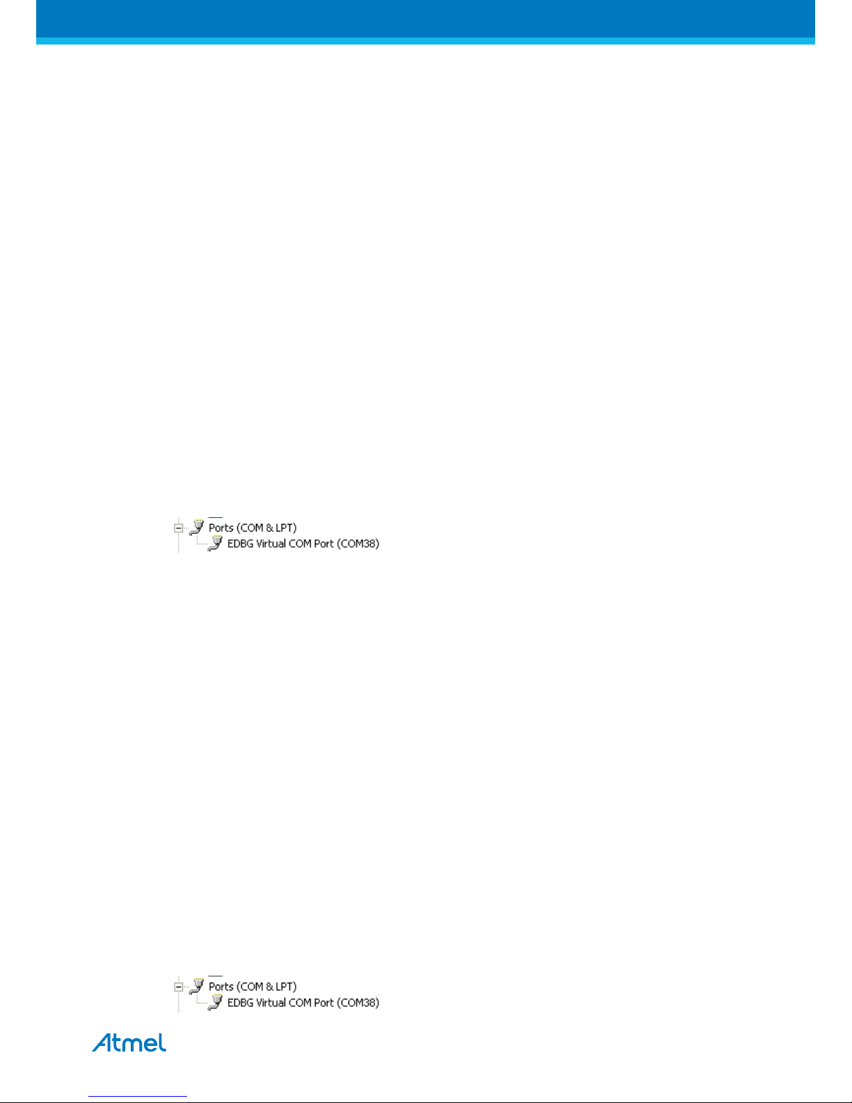
1.4.2 Connect the extension UART to the EBDG COM port
This section describes how to connect to the extension board UART by using the EBDG COM port.
All Xplained PRO boards have an embedded debugger (EBDG) with a number of features, among them a
CDC/COM port which enables the user to connect to the extension board UART and using the boot-loader on
the extension board.
1. Select a Xplained Pro board supported with a "Serial bridge application", currently supported by the
SAM4L XPRO and the ATMEGA256RFR2 XPRO boards.
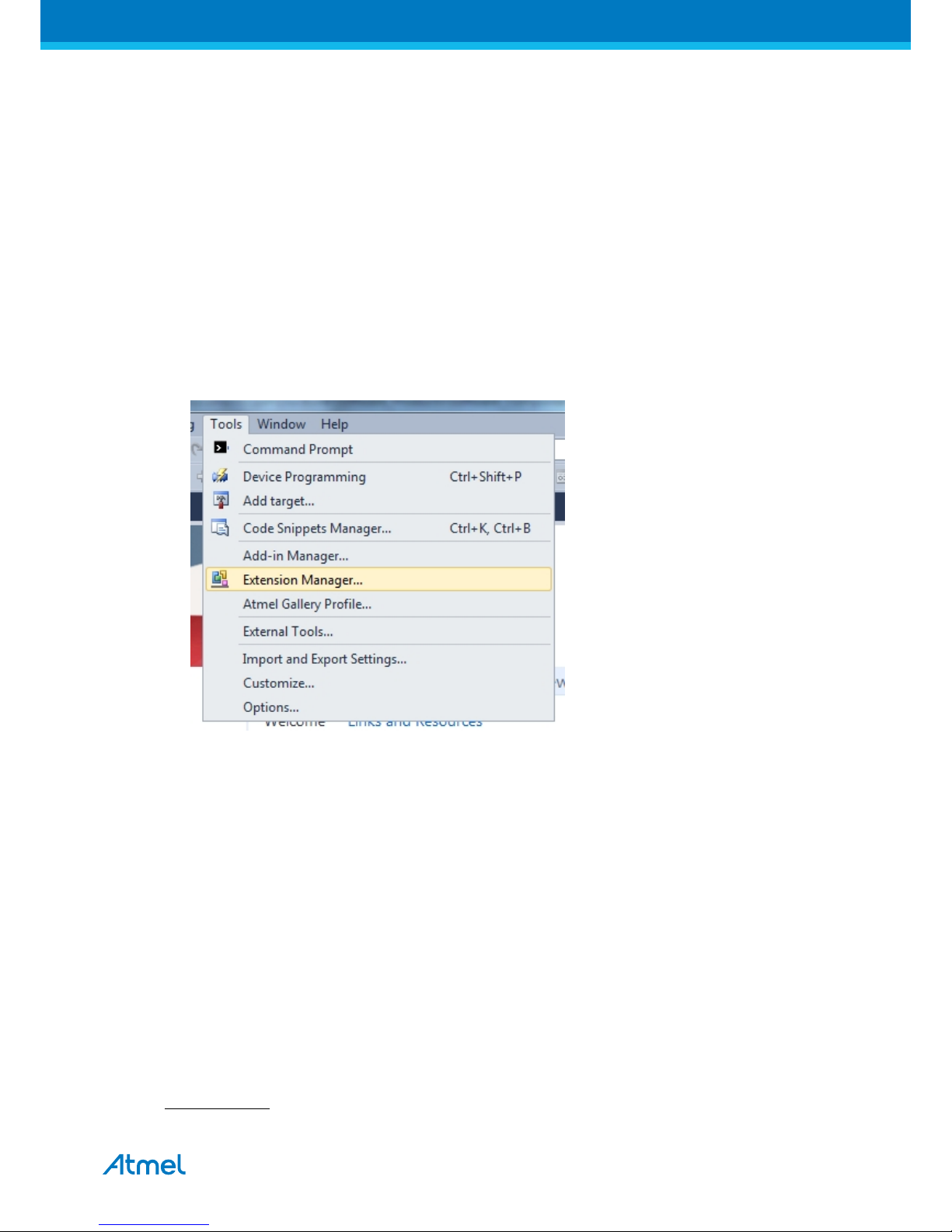
2. Download the "Wireless Library hex" extension using Atmel Studio Extension Manager
Atmel Studio: Tools/Extension Manager/Wireless, download and unzip in a directory of your choise
3. Connect the EDBG USB to the PC and Program the "Serial bridge application" hex file on the XPRO
board.
Atmel Studio: Tools/Device Programming, select the XPRO-EDBG as Tool and click Apply
Select "Memories" and locate the "Serial bridge application" hex file and click Program
4. The UART on EXT1 should now be connected to the EDBG COM port at 9600baud
1.5 Programming
How to program the extension
1.5.1 JTAGICE
How to program using the JTAGICE mkII and JTAGICE3.
1. Connect the JTAGICE USB to the PC
2. Connect the JTAGICE to the Extension board connector (J2) as shown on picture.
3. Go to Atmel Studio: Tools/Device Programming, and select the JTAGICE connected as Tool and click
Apply.
4. Select Device = ATxmega256A3U
5. Select "Memories" and locate the source hex or elf file and click Program
with pictures of connection to the extension board.
1.5.2 Boot loader
This section describes how to use the bootloader to program the ZigBit on the Extension board
1. Use a Xplained Pro board with a "Serial bridge application" (section 1.4.2) to connect the Extension board
UART to the Embedded debugger COM port or connect the "Extension board UART" using any other level
shifter solution you might have.
AT04357 RCB256RFR2-XPRO User Guide [USER GUIDE]
TBDA-MCU-09/2013
5
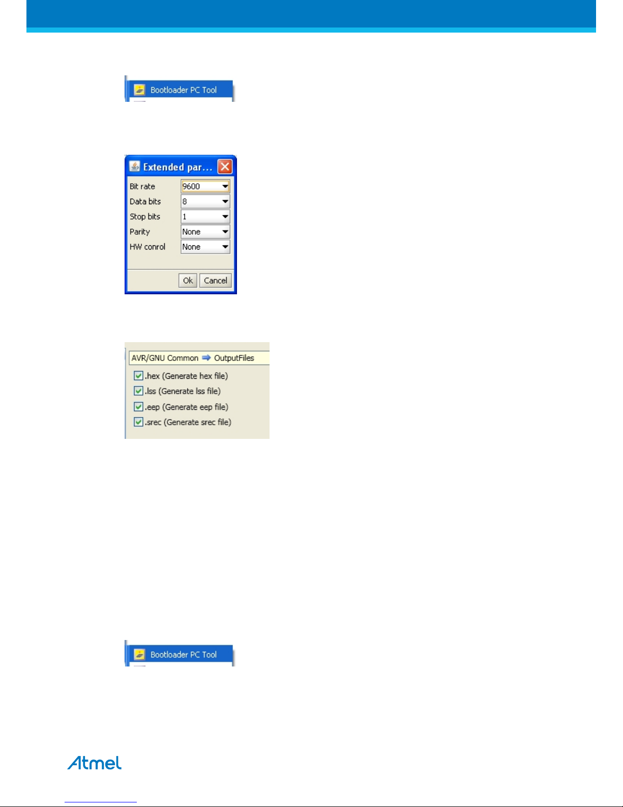
2. Start the "Bootloader PC tool" provided in the "Wireless Library hex" extension
3. Set "Connection" to Serial and "Port" to the COM port number
4. Configure the serial port settings as (click symbol at the right of Port setting)
5. "Select srec file", the file have to be of SREC format.
Atmel Studio output files can be of SREC format
6. Deselect EEPROM erase if not required.
7. Click "Upload"
8. Press the HW reset button (SW1) on the device if requested. The Bootloader PC tool will be waiting for
approximately 30 seconds for the button to be released. If this does not happen, programming will be
aborted.
9. Exit the GUI and reset the board - your new application should be up and running.
How to install the "Bootloader PC tool"
How to install the Bootloader PC GUI tool
1. Run the "Bootloader_PC_Tool_Setup_...exe" provided in the "Atmel AVR2054 Serial Bootloader" extension
from the Extension Gallery and complete the installation.
2. The Bootloader PC Tool is now available in the Atmel program folder
1.6 Available example code
SW examples provided for ATmega256RFR2 in Atmel Studio.
AT04357 RCB256RFR2-XPRO User Guide [USER GUIDE]
TBDA-MCU-09/2013
6
2. Performance Analyzer
2.1 Introduction
The Performance Analyzer FW together with the GUI in Atmel Studio Wireless Composer Extension provides a
number of basic functional RF tests.
A quick start guide and general help is provided in Wireless Composer once started.
2.2 Program installation
How to install necessary SW. (Details provided in "Getting Started Chapter")
1. Install Atmel Studio
1
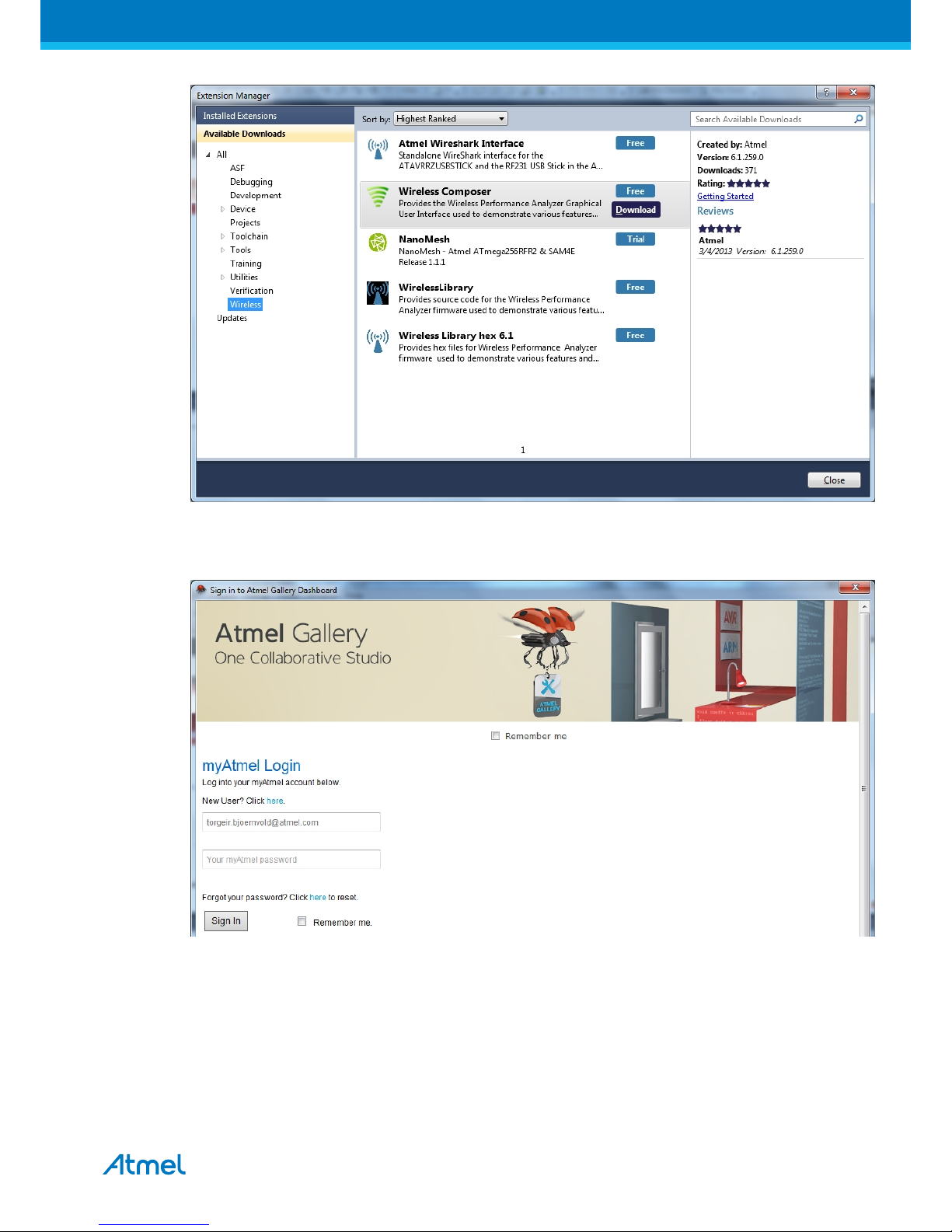
2. Once Studio is installed and started use the Tools - Extension Manager to install the Wireless Composer
Select Wireless and Wireless Composer
1
http://www.atmel.com/tools/atmelstudio.aspx
AT04357 RCB256RFR2-XPRO User Guide [USER GUIDE]
TBDA-MCU-09/2013
7
Log in to Atmel Gallery
Click download again and download starts
 Loading...