

Page 1
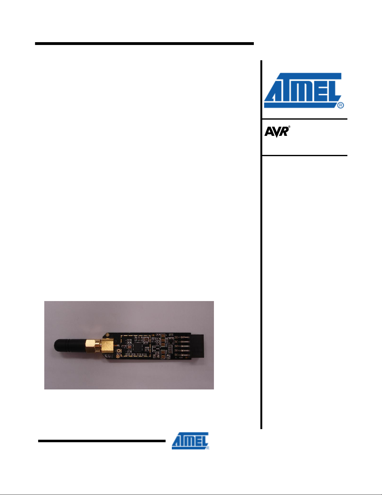
AT86RF231 Radio Board
W Manual
H
Features
Contains AT86RF231 radio transceiver.
•
Covers the 2.4GHz ISM band.
•
• On board ID chip for easy IEEE MAC address
1 Introduction
AT86RF231 Radio Board contains AT86RF231 radio transceiver.
It is highly acclaimed networking devices within low power personal area
networks.
connector that will enable the Radio board to be connected to ATMEL
microcontroller
transceivers in virtually any application segment.
Figure 1-1.
The AT86RF231 Radio Board sports an Atmel standardized 10-pin
– so as a customer you will be able
AT86RF231 Radio Board HW Overview
to evaluate Atmel radio
Microcontrollers
Application Note
Page 2
2 Related Items
3 Overview
AVR32 Studio (Atmel’s free IDE)
http://www.atmel.com/dyn/products/tools_card.asp?tool_id=4116
GNU Toolchain (Atmel’s free Compiler and Utilities)
http://www.atmel.com/dyn/products/tools_card.asp?too
JTAGICE mkII (On-chip programming and debugging tool)
http://www.atmel.com/dyn/products/tools_card.asp?tool_id=3353
AVR ONE! (On-chip programming and debugging tool)
http://www.atmel.com/dyn/products/tools_card.asp?too
This section gives an overview of the Radio Board from a system perspective and
what the kit contains and its minimum requirements. A set of condensed instructions
are then given on how to get the evaluation application for the kit up and running in
the shortest time possible.
AT86RF231 radio board: miniature carrier board with the AT86RF231 radio
transceiver mounted, SMA antenna connector, one wire ID chip and Atmel
standard 10-pin connector.
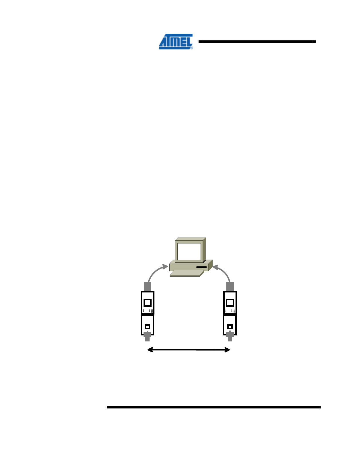
Figure 3-1 shows how the two processor boards paired with the radio frequency
boards also available in the kit can form a wireless peer to peer data connection over
USB.
Figure 3-1 AT86RF231 Radio Board used in conjuntion with PC
l_id=4118
l_id=4279
Processor Board
AT86RF231 Radio Board
RF Link
2
AVR600
Page 3

4 Hardware Description
This chapter describes the hardware about AT86RF231 Radio Board.
AVR600
AT86RF231 Radio Transceiver:
Second generation 2.4GHz ISM band radio transceiver with front
ends for antenna diversity and external power amplifier and encryption
accelerators.
Figure 4-1 Radio Board Overview
SMA con
GND
MISC signal
selector
Current sens
10 pin con
MISC signal
3
Page 4

4.1 Connectors
There are two main connectors on the board; one is the female SMA antenna
connector and in the opposite direction of the board is a 10-pin dual row header. See
Table 4-1 for pinout of this header.
Table 4-1. Radio Board 10-pin header
Pin Name Name
1 Reset Misc 2
3 Interrupt Sleep Transmit 4
5 Chip Select MOSI 6
7 MISO SCK 8
9 GND VCC (1.8 – 3.6V) 10
There are also two single row headers on the board:
• J103 (Not mounted): Two pin header that can be soldered in to do current
measurement with an ampere meter. R105 must be unsoldered to enable this
feature.
• J104 (Not mounted): Three pin header that can be soldered in to access the
auxiliary (Miscellaneous) signals from the radio transceiver.
Pin
4.2 Crystal
4.3 RF Front End
A high accuracy 16MHz crystal is mounted and used by the radio transceiver for
carrier frequency generation.
Since the output from the radio transceiver itself is a balanced signal pair, a balun is
needed to transform into a 50Ohm single ended signal fed to the SMA connector.
Johanson Technology provides one balun for the AT86RF231.
• 2450FB15L0001:
2.45 GHz filter balun optimized for
AT86RF231.
4
AVR600
Page 5

Figure 4-2 AT86RF231 Radio Board schematic
5
AVR600
Page 6

5 Connecting Radio Board to a Custom Board
The AT86RF231 Radio Board is used
Table 4-1 shows the pinout of the
It is possible to add the Radio Board to any routing as long as the required signals are
available. This is possible due to the Radio Board being able to be mounted
on the squid cable included in this kit. With this squid cable it is possible to route all
10 signals down onto a custom hardware. The reminder of this chapter shows a few
examples on how to wire these signals.
5.1 Default Supported Kits
Besides from being used on the processor boards the Radio Board can be
attached to wide range of Atmel evaluation and starter kits. The following kits are
supported directly. If you do not find your preferred kit here, please take a look at
section 5.2.
Table 5-1. Plug and Play Kits
Kit Name Comment
STK600
- Any ATxmega device Any of the digital ports can be used.
- ATmega164/324/644/1284P
STK500
- ATmega164/324/644/1284P
XPLAIN Any of the digital ports can be used.
EVK1104 Connect to WLESS header.
EVK1105 Connect to WLESS header.
in conjunction with the processor board.
standardized 10-pin bus.
5.2 Squid Cable
6
AVR600
There are two squid cables (10pin male header to single wires) included in the kit.
The intended use of this special cable assembly is to plug the radio frequency board
onto it, and connect the ten single wires to any hardware platform that does not have
the standard auxiliary connector available.
Table 5-2. Squid Cable Pinout
PIN
PIN
Pin 1 (Brown): Reset
Pin 3 (Orange): Interrupt
Pin 5 (Green): Chip Select
Pin 7 (Purple): Master In Slave Out
Pin 9 (White): Ground
Pin 2 (Red): Miscellaneous
Pin 4 (Yellow): Sleep Transmit
Pin 6 (Blue): Master Out Slave In
Pin 8 (Grey): SPI Clock
Pin 10 (Black): Vcc
Page 7

AVR600
5.3 Example AVR32: EVK1100
Intentionally left blank.
5.4 Example ARM7: AT91SAM7X-EK
Intentionally left blank.
6 Firmware
Table 6-1. Firmware Layout
Path File Comment
/Applications Parent folder for kit applications
/Applications/TAL_Examples/Wireless_UART Parent folder for wireless UART application
/Applications/TAL_Examples/Wireless_UART/Src Source Folder
/PAL Processor Abstraction Layer
/PAL/AVR32 Parent folder for AVR32 processor specific code
/PAL/AVR32/Generic/Inc Generic include files shared by all AVR32 devices.
/PAL/AVR32/Generic/Src Generic source code shared by all AVR32 devices.
/PAL/AVR32/UC3A3256 Parent folder for all AT32UC3A3256 specific code
/PAL/AVR32/UC3A3256/Boards/RZ600 Board specific code for the RZ600 kit
/PAL/AVR32/UC3A3256/Inc Include files for the processor code
/PAL/AVR32/UC3A3256/Src Source files for the processor specific code
/TAL Transceiver Abstraction Layer
/TAL/AT86RF231/Inc Include files specific to the AT86RF231 radio transceiver
/TAL/AT86RF231/Src Source files specific to the AT86RF231 radio transceiver.
/Resources Common resources used by all layers
/Resources/Buffer_Management/Inc
/Resources/Buffer_Management/Src
/Resources/Queue_Management/Inc
/Resources/Queue_Management/Src
7
Page 8

7 Appendix
7.1 FCC Statements
7.1.1 Equipment usage
This equipment is for use by developers for evaluation purposes only and must not be
incorporated into any other device or system.
7.1.2 Compliance Statement (Part 15.19)
These devices comply with Part 15 of the FCC Rules. Operation is subject to the
following two conditions:
1. These devices may not cause harmful interference, and
2. These devices must accept any interference received, including interference that
may cause undesired operation.
7.1.3 Warning (Part 15.21)
Changes or modifications not expressly approved by Atmel Norway could void the
user’s authority to operate the equipment.
7.1.4 Compliance Statement (Part 15.105(b))
This equipment has been tested and found to comply with the limits for a Class B
digital device, pursuant to Part 15 of the FCC Rules. These limits are designed to
provide reasonable protection against harmful interference in a residential installation.
This equipment generates uses and can radiate radio frequency energy and, if not
installed and used in accordance with the instructions, may cause harmful
interference to radio communications. However, there is no guarantee that
interference will not occur in a particular installation. If this equipment does cause
harmful interference to radio or television reception, which can be determined by
turning the equipment off and on, the user is encouraged to try to correct the
interference by one or more of the following measures:
• Reorient or relocate the receiving antenna.
• Increase the separation between the equipment and receiver.
• Connect the equipment into an outlet on a circuit different from that to which the
receiver is connected.
• Consult the dealer or an experienced radio/TV technician for help.
7.1.5 FCC ID
A09-1563 :
•
AIBA091563
8
AVR600
Page 9

AVR600
EVALUATION BOARD/KIT IMPORTANT NOTICE
This evaluation board/kit is intended for use for FURTHER ENGINEERING,
DEVELOPMENT, DEMONSTRATION, OR EVALUATION PURPOSES ONLY. It is
not a finished product and may not (yet) comply with some or any technical or legal
requirements that are applicable to finished products, including, without limitation,
directives regarding electromagnetic compatibility, recycling (WEEE), FCC, CE or UL
(except as may be otherwise noted on the board/kit). Atmel supplied this board/kit
“AS IS,” without any warranties, with all faults, at the buyer’s and further users’ sole
risk. The user assumes all responsibility and liability for proper and safe handling of
the goods. Further, the user indemnifies Atmel from all claims arising from the
handling or use of the goods. Due to the open construction of the product, it is the
user’s responsibility to take any and all appropriate precautions with regard to
electrostatic discharge and any other technical or legal concerns.
EXCEPT TO THE EXTENT OF THE INDEMNITY SET FORTH ABOVE, NEITHER
USER NOR ATMEL SHALL BE LIABLE TO EACH OTHER FOR ANY INDIRECT,
SPECIAL, INCIDENTAL, OR CONSEQUENTIAL DAMAGES.
No license is granted under any patent right or other intellectual property right of
Atmel covering or relating to any machine, process, or combination in which such
Atmel products or services might be or are used.
Mailing Address: Atmel Corporation, 2325 Orchard Parkway, San Jose, CA 95131
9
Page 10

Disclaimer
Headquarters International
Atmel Corporation
2325 Orchard Parkway
San Jose, CA 95131
USA
Tel: 1(408) 441-0311
Fax: 1(408) 487-2600
Atmel Asia
Unit 1-5 & 16, 19/F
BEA Tower, Millennium City 5
418 Kwun Tong Road
Kwun Tong, Kowloon
Hong Kong
Tel: (852) 2245-6100
Fax: (852) 2722-1369
Product Contact
Disclaimer: The information in this document is provided in connection with Atmel products. No license, express or implied, by estoppel or otherwise, to any
intellectual property right is granted by this document or in connection with the sale of Atmel products. EXCEPT AS SET FORTH IN ATMEL’S TERMS AND
CONDITIONS OF SALE LOCATED ON ATMEL’S WEB SITE, ATMEL ASSUMES NO LIABILITY WHATSOEVER AND DISCLAIMS ANY EXPRESS, IMPLIED
OR STATUTORY WARRANTY RELATING TO ITS PRODUCTS INCLUDING, BUT NOT LIMITED TO, THE IMPLIED WARR ANTY OF MERCHANTABILITY,
FITNESS FOR A P ARTICULAR PURPOSE, OR NON-INFRINGEMENT. IN NO EVENT SHALL ATMEL BE LIABLE FOR ANY D IRECT, INDIRECT,
CONSEQUENTIAL, PUNITIVE, SPECIAL OR INCIDENTAL DAMAGES (INCLUDING, WITHOUT LIMITATION, DAMAGES FOR LOSS OF PROFITS,
BUSINESS INTERRUPTION, OR LOSS OF INFORMATION) ARISING OUT OF THE USE OR INABILITY TO USE THIS DOCUMENT, EVEN IF ATMEL HAS
BEEN ADVISED OF THE POSSIBILITY OF SUCH D AMAGES. Atmel m akes no representations or warranties with respect to the accuracy or completeness of the
contents of this document and reserves the right to make changes to specifications and product descriptions at any tim e without notice. Atmel does not make any
commitment to update the information contained herein. Unless specifically provided otherwise, Atmel products are not suitable for, and shall not be used in,
automotive applications. Atmel’s products are not intended, authorized, or warranted for use as components in applications intended to support or sustain life.
© 2012 Atmel Corporation. All rights reserved
the registered trademarks or trademarks of Atmel Corporation or its subsidiaries. Windows® and others are registered trademarks or
trademarks of Microsoft Corporation in U.S. and/or other countries. Other terms and product names may be trademarks of others.
Web Site
http://www.atmel.com/
Literature Request
www.atmel.com/literature
. Atmel®, Atmel logo and combinations thereof, AVR®, AVR Studio®, STK® and others, are
Atmel Europe
Le Krebs
8, Rue Jean-Pierre Timbaud
BP 309
78054 Saint-Quentin-enYvelines Cedex
France
Tel: (33) 1-30-60-70-00
Fax: (33) 1-30-60-71-11
Technical Support
avr@atmel.com
Atmel Japan
9F, Tonetsu Shinkawa Bldg.
1-24-8 Shinkawa
Chuo-ku, Tokyo 104-0033
Japan
Tel: (81) 3-3523-3551
Fax: (81) 3-3523-7581
Sales Contact
www.atmel.com/contacts
 Loading...