

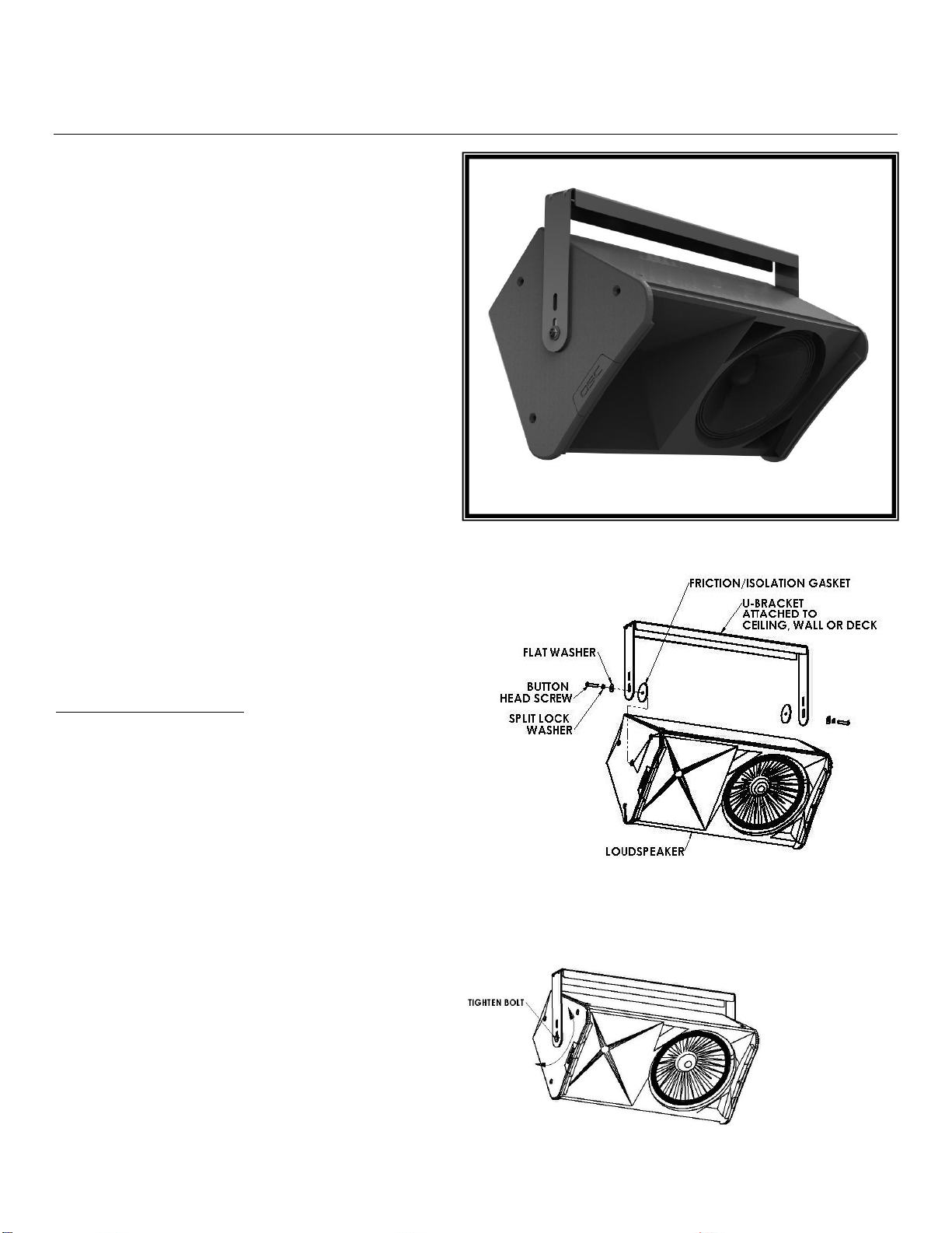
U-Bracket
Installation Instructions UB-325-13
The UB-325-13 U-Bracket is a mounting bracket that
attaches a loudspeaker to a wall, deck, ceiling, or
balcony and provides a one axis aiming feature.
Warning:
Mounting and/or rigging loudspeakers requires
experienced professionals.
loudspeakers can result in property damage,
personal injury, death and/or liability to the
installing contractor.
Note to Contractor: Due to the wide variety of wall
structures, materials and methods, the contractor should
exercise good judgment in selecting the proper mounting
area and hardware. Do not rely on drywall, acoustic tiles,
etc. to support the weight of any loudspeaker.
To assure a trouble free installation, read through and
follow these instructions carefully before beginning. If
you have doubts about the integrity of the structure you
are mounting to, or you are not sure about the proper
hardware to use, consult a structural and/or hardware
specialist. The structure should be capable of supporting 5
to 10 times the actual weight of the speaker. The use of a
back up safety system, such as a safety cable, is highly
recommended. Standard safety cables are available from
stock.
Contents:
Qty: Description
1 pc. U- Bracket Speaker Mount
1 pc. Instruction Sheet
1 bag Hardware kit package (M10 hardware)
Step 1: Place the U-Bracket over the speaker
cabinet to be sure you have the correct
mount. Sound isolation gaskets are placed
between the loudspeaker cabinet and the
U-Bracket’s arms. Also, compare the
included assembly hardware with that of
the loudspeaker. If threaded mounting points are not
provided by the manufacturer contact them for the correct mounting procedure.
Step 2: Select the mounting area where the
loudspeaker will be installed. Attach
the U-Bracket to the wall or ceiling
using the holes on the base of the UBracket. Use the appropriate hardware
for the application (if in doubt, consult
local hardware specialist). Tighten
permanently.
Improperly installed
2015 Adaptive Technologies Group Signal Hill, CA 90755 USA (562) 424-1100 092315_R2
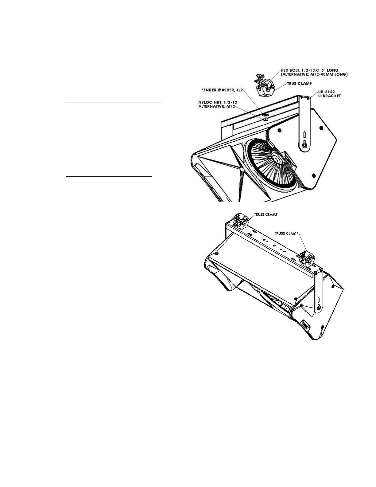
Figure 3
Figure 4
Step 3: Place the speaker between the U-Bracket’s arms. Insert the M10 Button head bolt, flat washer and split
lock washer (must match the speaker’s thread) through the hole in the arms with the sound isolation
gasket in between the speaker and the bracket. Thread the bolt into the loudspeaker. Repeat on the
other side of the speaker (Figure 1). Do not fully tighten yet.
Step 4: Rotate the loudspeaker into the
desired direction then tighten the side
bolts permanently (Figure 2).
Step 5: Truss Clamp Application:
For a single truss clamp application,
attach the truss clamp on the center
hole of the U-bracket’s base using a
½-13x1.5” long hex bolt, ½ fender
washer and a ½-13 nylock nut (M12
hex bolt, M12 fender washer and M12
nylock nut can also be used). Position
the desire direction of the loudspeaker
then tigthen nut (figure 3).
For dual truss clamp application,
attach the truss clamp on the two
holes of the u-brackets base close to
the bend. Use ½-13x1.5” long hex
bolt, flat washer and nylock nut (M12
bolt, fender washer and nyloc nut can
also be used) (Figure 4).
Step 6: Recommendation: Safety Cable
Install a safety cable to the U-Bracket and to
the structurally load rated mounting surface.
2015 Adaptive Technologies Group Signal Hill, CA 90755 USA (562) 424-1100 092315_R2
 Loading...