


INST
L
S
E
S
E
S
E
To
next
From:
device
ALLA
TION AND MAINTENANCE INSTRUCTIONS
AGB02
Fire
Str
obe Light
Specifications
V
oltage R
ange:
Power Consumption: 35mA 1.5W Max
Flash
Frequency:
Oper
ating T
Brightness: 120 cd/m2
IP Rating: IP54
Standard:
Clause 9.7 of BS5839, EN54-23: 2010, HKFSD circular 4/2001, UL1638
General Description
AGB02 Fire Strobe Light utilizes super bright LEDs which generates a
high-intensity light, visible from all sides of the lens to provide a visible
notification signal for the purpose of life safety and property protection.
It is ideal to be installed at hotels, apartments, hospitals, commercial
buildings, residential buildings, shopping malls or wherever visible
alarms are required.
Having considered power saving for the fire alarm system, we adopted
the best quality LEDs, which consume less current while maintaining
the brightness comparable to the traditional Xenon strobe does.
Besides, customers can also save on material costs by slashing the
battery and the battery charger size. For facilitating the wiring work,
our strobes can achieve self synchronization through power cables
and no additional signal cables or equipment are required.
emper
ature:
DC or F
1-2.5 Hz
-10° C
ull-Wave R
self-Synchronized
to 65° C
ectified 24-volt models – 18
NO
TICE: This manual shall be left with the owner/user of this equipment.
Fir
e Alarm System Considerations
Power Supply Considerations
P
anels typically supply DC filter
r
ectified) voltage
number of units used in a zone based on the type of panel supply. Be
certain the sum of all the de
capability of the panel.
curr
ent found in the subsequent charts and must be the current
specified for the type of panel power sup
System Wiring
Figur
e 1. Strobes power
(+)
FACP
or
MODULE
(–)
. The system design engineer must calculate the
Calculations ar
: Self-Synchr
ed in tandem by a 2-wir
(+)
T
R
O
B
(–)
(+)
device
or EOL
(–)
ed v
oltage or FWR (full-wav
vice curr
ents do not exceed the curr
e based on using the de
ply used.
onized Devices
(+)
T
R
O
B
(–)
+24V GND
e cir
sticker
(+)
(–)
cuit:
(+)
T
R
O
B
(–)
jumpers
FACP, module
or previous
ent
vice
to 28 volts
Wire
Sizes
The designer must be sure that the last de
v
oltage to oper
v
oltage available to the last device, it is necessary to consider the v
dr
op due to the r
v
oltage dr
the system, it is best to consider all of the de
of the supply cir
ate the de
esistance of the wire.
op. Gener
ally,
cuit (simulates “wor
vice within its r
for purposes of determining the wir
vice on the cir
ated v
oltage
The thicker the wire,
vices as “lumped”
st case”).
. When calculating
e size necessary for
T
ypical wire size r
18 AWG solid:
16 AWG solid:
14 AWG solid:
12 AWG solid:
Ex
ample: Assume you have 10
mA average and 2
return). The v
10 de
vices x 3 ohms/1,000 ft. x 2
e
The same number of devices using 12 A
dr
op. The same de
Consult y
v
oltage range to determine acceptable voltage drop.
Note: If class “A
the single wire length in this calculation.
Flash Rate
Strobes ar
may be selected using the jumper plugs located on the printed circuit board.
You can discover the sticker to find the jumpers.
Figur
e 2. Jumper Setting
E
O
NO
TE: Always power do
1
esistance:
000 Ft. of 14 AWG
oltage at the end of the loop is 0.050 amps per de
our panel manufactur
” wiring is installed, the wir
Selections
e factory set for 1.5Hz (90 flashes per minute). Four frequencies
The right jumper is plugged: 1Hz (60 flashes per minute)
No jumper is plugged: 1.5Hz (90 flashes per minute)
The left jumper is plugged: 2Hz (120 flashes per minute)
Both jumpers are plugged: 2.5Hz (150 flashes per minute)
Approximately 8 ohms/1,000 ft.
Approximately 5 ohms/1,000 ft.
Approximately 3 ohms/1,000 ft.
Approximately 2 ohms/1,000 ft.
de
vices on a zone and each r
wiring (total length=outgoing +
000 ft =3 v
vices using 18 A
er’
s specifications
olts dr
WG wir
WG wir
e will pr
e length may be up to 4 times
wn de
vices before setting jumpers.
op.
e will pr
, as w
oduce only 2 v
oduce 8 v
ell as the oper
cuit has sufficient
the
olt
age
the less
equir
vice x
AGB02-25
the
on the end
es 50
olts
olts dr
op.
ating
-00
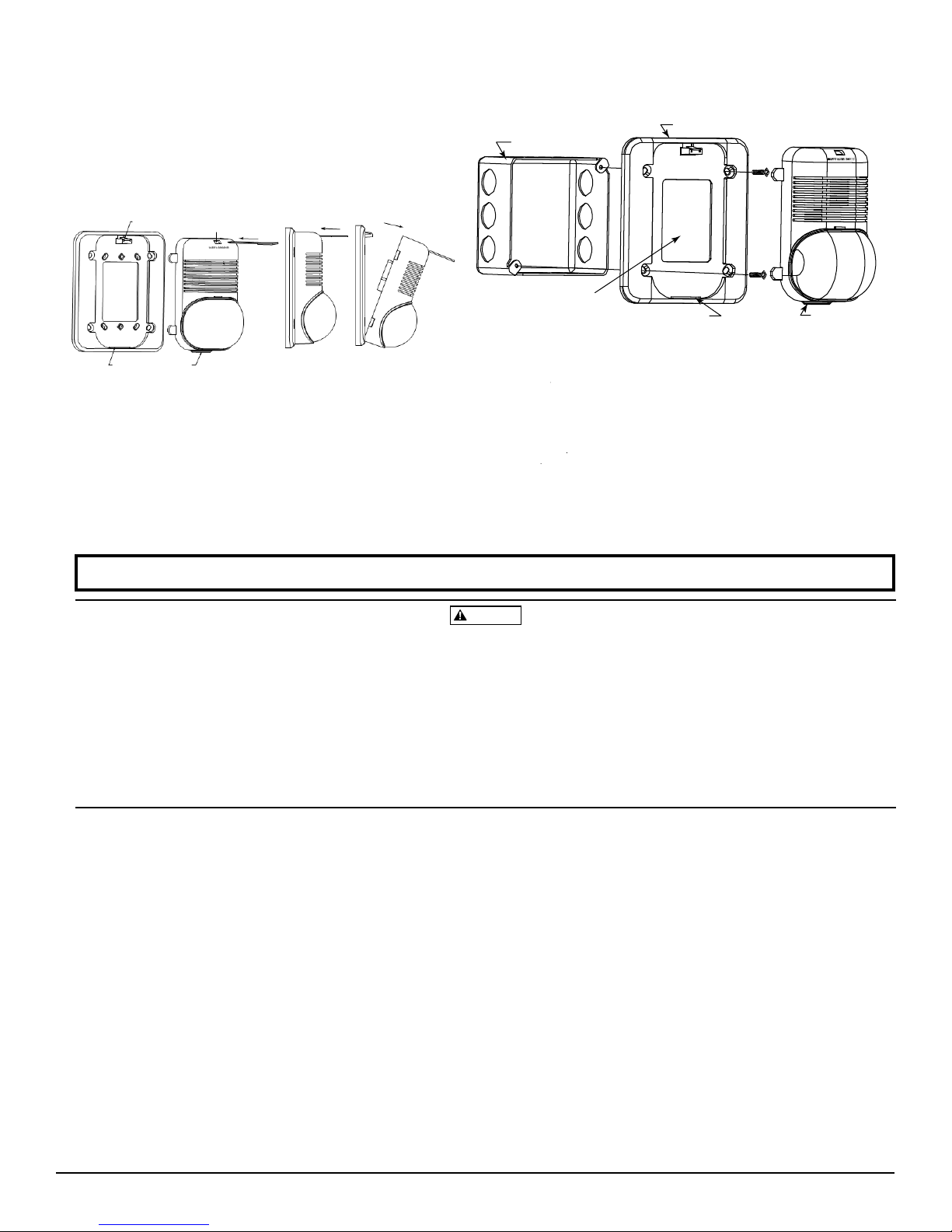
Mounting Diagrams
Figur
e 3: Removal of str
To r
emove
strobe fr
sc rewdriver
screwdriver
str
obe module, disengage the Locking Rib
fr
om the mounting plate.
PLASTI C SNAP LEVE R
as sho
to r
elease the snap, pull back on the str
obe fr
om mounting plate:
om mounting plate, insert sui table slotted
wn to unlock snap. While
INSER T SCREW DRIVER
pushing in the slotted
obe
, and lift the str
. Hinge the
obe away
TAB SL OT
TAB
Please r
The
str
obe will not w
from the fire/security panel monitoring the
off for an
visual warning.
y r
eason, the horn/str
The signal strobe may not be seen. The electr
uses e
xtr
The str
emely reliable LED lights. It flashes at least once every second.
obe must not be installed in dir
intensity (over 60 foot candles) where the visual flash might be disr
egar
ded or not seen. The str
ATM
w
arr
ants its enclosed str
workmanship under normal use and service for a
date of manufacture.
No agent, repr
authority to incr
The Company’s obli
r
eplacement of an
materi
als or w
y
ear
period commencing with the date of manufacture.
ATM’s
orkmanship under normal use and service during the two
service
defective units postage pr
2
ork without power.
ATM
esen
tative,
ease or
alter the obligations or limitations of this Warr
gation of this Warranty shall be limited to the repair or
y part of the strobe
number for a R
efer to inser
t for the Limitations of Fir
The
str
obe gets its power
alarm system. If power is cut
obe will not provide the desir
onic visual w
ect sunlight or ar
obe ma
y not be seen b
obe
to be free from defects in materials and
y the visually impair
period of two year
makes no
dealer
other e
, or employ
xpr
ess w
arranty for this strobe
ee of the Compan
which is found to be defective in
eturn Authorization number
epaid to ATM or the distributor.
The Limitations of
ed audio or
arning signal
eas of high
Two-Year Limited War
s fr
y has the
After phoning
, send
Figur
e 4:
Str
obe with mounting plate and back box
4-INCH BACK BOX
MOUNT ING P LATE
WALL OPENING MUST
EQUAL PLATE OPENING
1. Mount plate to back bo
is
equal to the plate opening.
2. Complete field wiring.
3. Insert locking rib into slot on plate
4. Press into plate, unit will make a “click” when it has locked into
place.
Scr
ew types used for mounting: 8-32 x
WARNING
Str
obes
The signal strobe may cause seizures.
photic response to visual stimuli with seizures, such as per
epilepsy,
str
obe signals
The signal strobe cannot oper
power supplies produce interrupted power.
light
terrupted source of power in or
ed.
ranty
om
anty
Please include a note describing the malfunction and suspected cause
of failure.
.
which ar
modifications, or alter
.
no case shall the Compan
damages for breach of this or an
whatsoever,
negligence or fault. Some states do not allo
of
incidental or consequential damages, so the above
exclusion may not apply to you. This Warranty giv
rights, and you may also have
AGB02-25
LOCK ING RIB SLOT
x using screws A, making sure w
.
3⁄
4
flat head
e Alar
m Systems
Individuals who have
should avoid pr
, including this str
olonged exposur
obe
, ar
e activ
ate fr
om coded power supplies
e to environments in which
ated.
The strobe must have
der to operate correctly.
The Compan
y shall not be obligated to r
e found to be defective because of damage
ations occurring after the date of man
y be liable for an
y other Warr
y consequential or incidental
anty
even if the loss or damage is caused by the Company’s
w the e
other rights which vary fr
LOCK ING RIB
all opening
positiv
sons with
. Coded
an unin-
epair or replace units
, unreasonable use
ufacture.
, e
xpr
essed or
xclusion or limitation
es y
ou specific legal
om state to state
implied
limitation or
-00
e
,
In
.
 Loading...