

Page 1

Installation Guide
AT-VCC-RELAY-KIT
IP to Relay Command Converter for Velocity Control System
AT-VCC-RELAY-KIT
The Atlona AT-VCC-RELAY-KIT is an accessory for the Atlona Velocity™ Control System that
provides conversion between IP control commands and relay / sensor signals. This Velocity
Control Converter is very compact and can be placed anywhere a device requires control and
is not IP-capable. The VCC-RELAY-KIT is remotely powered through Power over Ethernet (PoE),
or locally from a USB power source. The primary unit installs onto any surface via a convenient
mounting dock. A simple “click” locks it into place for a secure, reliable installation. The control
port module supports DIN rail installation, and features four relay outputs plus four sensor inputs.
The inputs and outputs are both congurable for various operating modes.
Package Contents
1 x AT-VCC
1 x AT-VCC-RELAY
Operating Notes
• The Velocity Command Converter must be on the same network as the Velocity Gateway
(AT-VGW-250) or it will be unable to sync for control.
• The AT-VCC-RELAY-KIT is PoE, to power the unit, simply plug it into a PoE compatible
network switch. If the network switch is not PoE capable, a PoE injector (purchased separately)
or USB can be used.
• All devices (AT-VCC, Velocity, AT-VTP, switchers, etc) should be set to static IPs or the
DHCP IP address reserved for each individual device.
IMPORTANT: Velocity Gateway (AT-VGW-250) must be set up before the AT-VCC-RELAYKIT is fully functional.
1
Page 2
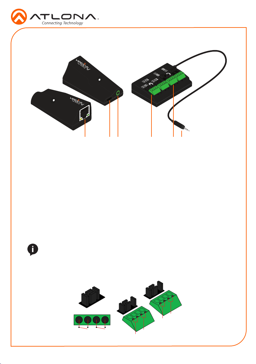
Panel Description
Installation Guide
AT-VCC-RELAY-KIT
Voltage
Sensor
Contact
Closure
SPDT
DPDT
SPST
1
1 Ethernet
Connect an Ethernet cable from this
port to the same network as the Velocity
Gateway.
2 USB
Optional - Connect a mini USB to USB
cable here for power.
3 3.5mm Port
Connect to a VCC relay connector.
2
3
4
4 Relay
Connect relay here, adjusting the jumpers
to set the unit to the correct mode.
5 Sensor
Connect sensor here, adjusting the
jumpers to the correct mode.
6 3.5mm Connector
Connect the 3.5mm connector to the
3.5mm port of the VCC.
6
5
Relay
The relay has 4 terminals which vary in function depending on how the jumpers above the ports
are set.
NOTE: Relays can only work up to a maximum of 24V and 500 mA current.
Single Pole, Single-Throw (SPST)
Place the jumpers as shown below, this can be done to a single connector or to both to create up
to 4 independent relays.
SPST
SPST
4
3
1
22
1
2
Page 3
Installation Guide
AT-VCC-RELAY-KIT
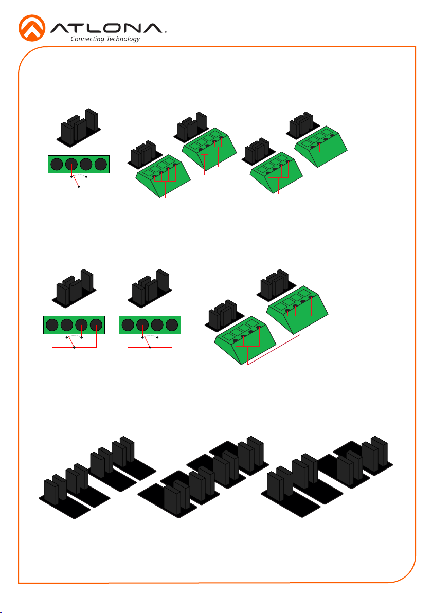
Single Pole, Double-Throw (SPDT)
Place the jumpers as shown below, this can be done to a single connector or to both to create up
to 3 independent relays.
SPST
SPDT SPDT
SPDT
3
2
1
Double Pole, Double-Throw (DPDT)
When DPDT is selected within Velocity, it will create 2 relays that work simultaneously. If one
port is opened, the other will open at the same time. The DPDT is a variant of the SPDT and the
jumpers must be placed exactly as below to work.
DPDT
1 2
1
1
2
Sensor
The ports can be set to sense either voltage or contact closure. Contact closure will react to the
change in current, while voltage will react to voltage as low as +/- 3V or as high as +/- 24V.
Both ports are set to
Contact Closure
Both ports are set to
Voltage Sensor
3
The ports are set to Contact
Closure for the rst two ports and
Voltage Sensor for the last two.
Page 4

Installation Guide
AT-VCC-RELAY-KIT
IP
The AT-VCC is set to DHCP by default. If the network does not support DHCP, it will
automatically set the AT-VCC to the static IP of 192.168.1.70 after 30 seconds.
VHelp and webGUI
Velocity will nd the VCC when scan network is used, but if the VCC needs to be set up o site
rst, the software VHelp can be used.
1 Connect the AT-VCC to a network switch (PoE is best if a PoE switch is not available, a
power injector or mini USB to USB cable may be used).
2 Download VHelp from the resource tab of http://atlona.com/AT-VCC-RELAY-KIT.
3 Unzip the le to the local PC
4 Double-click the VHelp executable to open the program. Vhelp will start discovery as soon
as the program is opened.
5 Double click on the VCC (to determine the correct one, look on the bottom of the VCC for
the MAC address). The PC default browser will open to the AT-VCC webGUI.
NOTE: It is best to use the webGUI to set up the static IP only, as set up in Velocity
will override any settings selected in the VCC page of the webGUI.
6 Select Network Settings to open the IP conguration page.
7 Select the DHCP Enabled header, this will disable DHCP and allows IP settings to be edited.
8 Type in the IP details to
match the network details
of the Gateway. e.g. If the
Velocity gateway is located at
the IP of 192.168.12.15, then
the VCC should be set to an
IP within the 192.168.12.XXX
range that has not already
been used.
4
Page 5

Installation Guide
Installation and Set Up
NOTE: Installation of the Velocity Command Converter can only be done after the
VGW-250 has been set up. View the AT-VGW-250 Installation Guide and Velocity
Manual for instructions.
1 Connect the Relay connector into the 3.5mm port on the unit.
2 Connect the Ethernet connector into the front port of the VCC.
a If the Ethernet cable is connected to a non PoE switch, use a PoE injector (purchased
separately) or a mini USB to USB cable to a USB port on a wall port or device that
supports USB power.
3 Open any browser on the network and type in the IP address of Velocity.
4 Select the = button from the top left corner and select Sites.
AT-VCC-RELAY-KIT
5 Select the building that corresponds with the room of the VCC.
6 Select the room the VCC is located in. A new screen will take over the window and display
the technology in the room.
7 Select the + button located at the top right corner of the room. A new menu will open.
5
Page 6

Installation Guide
AT-VCC-RELAY-KIT
8 Press the scan network button. All Atlona devices found will appear in the unassigned list.
9 Select the Add button next to the VCC. A new pop up will appear.
10 Select VCC Relay/Sensor. The AT-VCC will be added to the room.
11 Select edit on the VCC box. A new side menu will open.
12 Select the options that correspond with how the VCC will be used.
NOTE: The sensor ports should automatically ll, but if there is no port information
under Sensor Ports, ll in the following settings: Port 1 - 9156, Port 2 - 9157, Port 3 -
9158, Port 4 -9159.
6
Page 7

Connection Diagram
AT-VCC-RS232
AT-VTP-800-WH
Projector
Installation Guide
AT-VCC-RELAY-KIT
2
1
ETHERNETHDMI OUTMDP OUT DC 19V
AT-VGW-250
AT-VGW-250
2
(redundancy)
1
ETHERNETHDMI OUTMDP OUT DC 19V
AT-VGW-250
AT-VGW-250
Ethernet / PoE
Ethernet / PoE
AT-VCC
Voltage
Sensor
Contact
Closure
SPDT
DPDT
SPST
Control
AT-VCC-RELAY
AT-VCC
Ethernet
IT Room
Ethernet / PoE
Ethernet
AV LAN
Ethernet / PoE
Ethernet / PoE
AT-VCC-IR
AT-VCC
Display
Control
AT-VTP-550-BL
Ethernet / PoE
Room n + 1
Projector
Screen
Room 1
Ethernet / PoE
AT-VTP-800-BL
AT-VCC-IR
AT-VCC
Display
Control
Room 2
7
Page 8

Installation Guide
AT-VCC-RELAY-KIT
Version 1
atlona.com • 408.962.0515 • 877.536.3976
© 2017 Atlona Inc. All rights reserved. “Atlona” and the Atlona logo are registered trademarks of Atlona Inc. All other brand names and trademarks or registered
trademarks are the property of their respective owners. Pricing, specications and availability subject to change without notice. Actual products, product images, and
online product images may vary from images shown here.
8
 Loading...