

Page 1
Installation Guide
AT-UHD-SW-510W
4K/UHD Five-Input Universal Switcher with Wireless
Presentation Link
AT-UHD-SW-510W
The Atlona AT-UHD-SW-510W is a 5×1 multi-format switcher with wireless presentation
capability. It provides universal BYOD (bring your own device) compatibility with HDMI,
DisplayPort, and USB-C inputs, plus wireless connectivity for mobile devices. The SW-510W
is HDCP 2.2 compliant, and features an HDMI output and a mirrored HDBaseT™ output that
can be used with the Atlona AT-UHD-EX-100CE-RX-PSE HDBaseT receiver. It also includes
automatic input switching and automatic display control capability, both applicable to wired and
wireless source connections. Additionally, the SW-510W can be integrated with an occupancy
sensor to automatically power up the unit and display (available in rmware 1.1 or greater).
This unique multi-format switcher and wireless gateway provides a universal connectivity solution
for presentation devices in a wide range of professional AV applications.
Package Contents
1 x AT-UHD-SW-510W
1 x Captive screw connector, 5-pin
1 x Captive screw connector, 4-pin
2 x Captive screw connector, 3-pin
2 x Wi-Fi antenna modules
1 x USB-C cable, 2 meters
1 x 24V DC power supply
2 x Mounting plates
4 x Mounting screws
1 x Installation Guide
IMPORTANT: Visit http://www.atlona.com/product/AT-UHD-SW-510W for the latest
rmware updates and User Manual.
1
Page 2

Installation Guide
USB-C
DP
HDMI 3
HDMI 4
BYOD
DISPLAY
INPUT
AT-UHD-SW-510W
AT-UHD-SW-510W
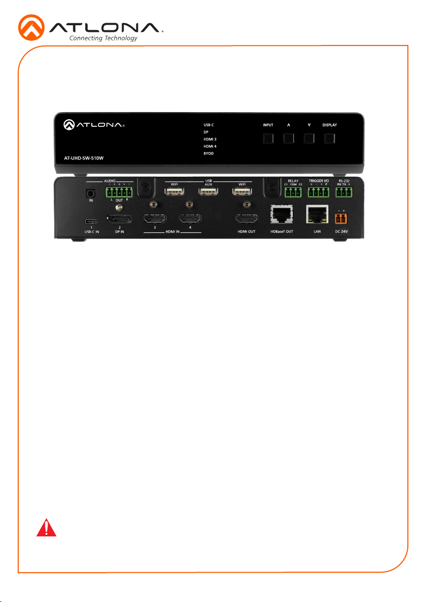
Panel Descriptions
AT-UHD-SW-510W
5 6 7 8 9 10
AUDIO
+
+
L R
IN
OUT
1
USB-C IN
2 3 4
DP IN
11 12
1 Input Indicators
Displays the currently selected input.
2 INPUT
Press this button to cycle through each
input.
3 Cursor Buttons
Adjust the volume on the display.
4 DISPLAY
Press this button to toggle the power state
of the desired display.
5 AUDIO IN
Connect a 3.5 mm mini-stereo cable from
an analog audio source to this connector.
6 AUDIO OUT
Use the included captive screw connector
to connect a balanced audio device.
7 USB
Connect the included Wi-Fi antenna
to either WiFi ports. The AUX port is
reserved. Refer to Installation, on page 8,
for more information.
8 RELAY
Connect one of the included 3-pin captive
screw connectors to this port to control
screens, drapes, lights, or other devices.
9 TRIGGER I/O
Connect voltage-controlled device to this
port. A 4-pin captive screw connector is
required.
13
3 4
21
USB-C
DP
HDMI 3
HDMI 4
BYOD
USB
USB
USB
INPUT
RELAY
WiFiWiFi AUX
USB
HDMI OUTHDMI IN
C1
HDBaseT OUT
DISPLAY
TRIGGER I/O
RS-232
+
COM
C2
RXPTX
+
LAN
DC 24V
14 15 16 17
10 RS-232
Use the included captive screw connector
to connect an RS-232 controller or
automation system.
11 USB-C
Connect a USB-C cable from this port to
a USB-C source.
12 DP IN
Connect a DisplayPort device to this port.
13 HDMI IN
Connect an HDMI cable from each of
these ports to a UHD/HD source.
14 HDMI OUT
Connect an HDMI cable from this port
to an HD/UHD display.
15 HDBaseT OUT
Connect to a locally powered HDBaseT
receiver such as the AT-UHD-EX-100CERX-PSE.
16 LAN
17 DC 24V
Connect an Ethernet cable from this port
to the network.
Connect the included power supply to
this port using the included 2-pin captive
screw connector.
2
Page 3
Installation Guide
AT-UHD-SW-510W
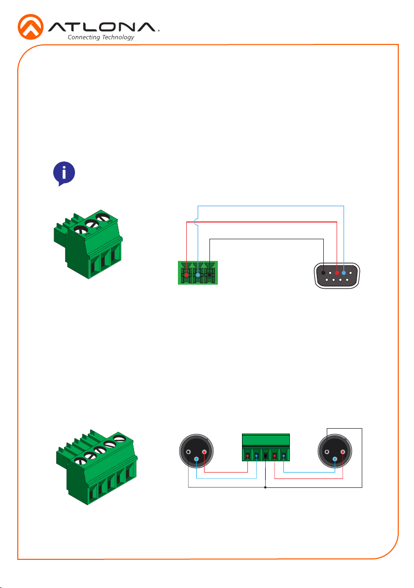
RS-232
The AT-UHD-SW-510W provides an RS-232 port which allows communication between an
automation system and an RS-232 device. This step is optional.
1. Use wire strippers to remove a portion of the cable jacket.
2. Remove at least 3/16” (5 mm) from the insulation of the RX, TX, and GND wires.
3. Insert the TX, RX, and GND wires into correct terminal using one of the included 3-pin
captive screw connectors.
NOTE: Typical DB9 connectors use pin 2 for TX, pin 3 for RX, and pin 5 for ground.
On some devices functions of pins 2 and 3 are reversed.
TX
RX
GND
Audio
The AT-UHD-SW-510W provides the ability to output two-channel balanced analog audio on the
AUDIO OUT port, using the included 5-pin captive screw connector. This step is optional.
Use wire strippers to remove enough insulation to allow each wire to be securely fastened
to each terminal of the captive screw connector block and connect the wires as shown.
Unbalanced audio is not supported.
1 2
3
+
-
GND GND
1 2
3
-
+
Balanced XLR audio
3
Page 4

Installation Guide
AT-UHD-SW-510W
Relay (rmware version 1.1 and greater)
The AT-UHD-SW-510W provides a RELAY port, allowing the control of screens, curtains, and
other devices. Use a 48 V DC relay with no more than 1 A current draw.
When the AT-UHD-SW-510W is powered-on or rebooted, C1 and C2 are set to the Normally
Open (NO) state.
C1
COM
C2
Trigger (rmware version 1.1 and greater)
The TRIGGER I/O port allows voltage-controlled devices, such as an occupancy sensor, to
be connected to the AT-UHD-SW-510W. Use the included 4-pin captive screw connector to
connect the device. Voltage range is 3 to 30 V DC.
- + P
Powered sensor
- + P
Passive sensor
4
Control (Set HIGH)
Common (Set LOW)
+12 V DC
Control (Set HIGH)
Powered sensor
30 V (max.)
Passive sensor
Page 5

Installation Guide
AT-UHD-SW-510W
Power Connector
Locate the included orange captive screw connector and wire the included power supply to the
block, as shown below. Do not use high-torque devices, when securing the wires, as this may
damage the screws and/or connector block.
White (positive)Black (negative)
24 V
Mounting Instructions
The AT-UHD-SW-510W can be mounted in dierent ways, based on the number of units that are
being installed. The AT-UHD-SW-510W can be mounted in a rack or on/under any at surface.
NOTE: AT-UHD-510W-RM rack ears are sold separately. Contact Atlona for more
information.
Single-unit rack installation
1. Attach the included small rack ear (sold separately) to one side of the AT-UHD-SW-510W,
using the included screws.
2. Attach the included longer rack ear (sold separately) to the opposite side of the AT-UHDSW-510W using the included screws.
DISPLAYINPUT
USB-C
DP
HDMI 3
HDMI 4
BYOD
AT-RON-444
AT-UHD-SW-510W
+
5
Page 6

Installation Guide
USB-C
AT-UHD-SW-510W
USB-C
DP
HDMI 3
HDMI 4
BYOD
AT-UHD-SW-510W
Dual-unit rack installation
1. Turn both units upside-down on a at surface, next to each other, as shown.
2. Position the included mounting plates over the holes on the bottom of the enclosure.
When attaching mounting plates, the countersink bevels on the mounting plate should face
upward.
Countersink bevel
BYOD
HDMI 4
HDMI 3
DP
USB-C
AT-UHD-SW-510W
BYOD
HDMI 4
HDMI 3
DP
3. Turn the attached units over and install the rack ears (sold separately) to one side of each
enclosure using the included screws.
INPUT
DISPLAY
DISPLAYINPUT
USB-C
DP
HDMI 3
HDMI 4
BYOD
AT-RON-444
DISPLAYINPUT
AT-UHD-SW-510W
+
USB-C
DP
HDMI 3
HDMI 4
BYOD
AT-RON-444
AT-UHD-SW-510W
6
Page 7

Installation Guide
AT-UHD-SW-510W
AT-UHD-SW-510W
USB-C
DP
HDMI 3
HDMI 4
BYOD
AT-UHD-SW-510W
Flat surface
1. Turn the unit upside down a at surface.
2. Position the included mounting plates over the pre-drilled holes on the bottom of the
enclosure. When attaching mounting plates, the countersink bevels on the mounting plates
should face upward.
Countersink bevel
3. Mount the unit using the circular holes, on each mounting plate. If using a drywall surface,
a #6 drywall screw is recommended. Mounting screws are not included.
AT-RON-444
DISPLAYINPUT
+
USB-C
DP
HDMI 3
HDMI 4
BYOD
NOTE: The unit can also be mounted under a at surface, such as a table, by
turning the unit upside down.
7
Page 8
Installation Guide
USB-C
DP
HDMI 3
HDMI 4
BYOD
DISPLAY
INPUT
AT-UHD-SW-510W
AT-UHD-SW-510W
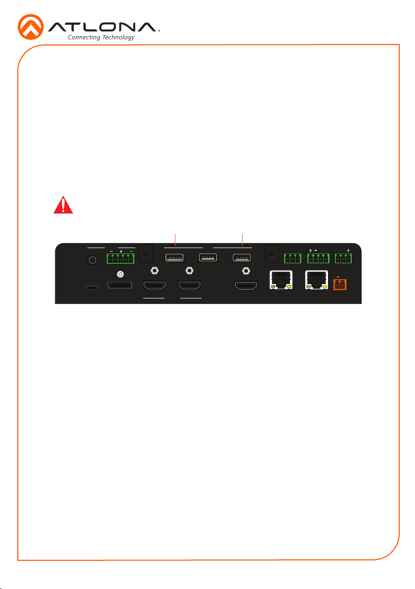
Installation
1. Connect a USB-C cable from a source to the USB-C (1) port.
2. Connect a DisplayPort cable from a source to the DP IN (2) port.
3. Connect up to two UHD/HD sources, using HDMI cables, to the HDMI IN (3) and HDMI IN
(4) ports.
4. Connect an HDMI cable from the HDMI OUT port to a UHD/HD display.
5. Connect up to two USB wireless antenna modules to the identied USB (WiFi) ports, below.
Two USB wireless antennas are included. WiFi (1) supports Google Cast™ and Apple
AirPlay®. WiFi (2) supports Miracast™, only. The AUX port is reserved for obtaining the IP
address of the unit. Refer to Obtaining the IP Address on page 10 for more information.
IMPORTANT: Only use Atlona Wi-Fi USB modules. Other Wi-Fi modules may
not be supported by this product.
AUDIO
+
+
L R
IN
OUT
USB
USB
USB-C IN
1
2 3 4
DP IN
21
TRIGGER I/O
RELAY
COM
C1
WiFiWiFi AUX
USB
USB
HDMI OUTHDMI IN
C2
HDBaseT OUT
RS-232
+
RXPTX
+
LAN
DC 24V
6. Connect the relay leads from the control motors of the projection screen, blinds, or curtains,
7. Connect a trigger device, such as an occupancy sensor switch, to the TRIGGER I/O port.
8. Connect a 3.5 mm analog audio cable from an analog source to the AUDIO IN port.
9. Connect an Ethernet cable from the LAN port to the Local Area Network (LAN).
10. Connect an Ethernet cable from the HDBaseT port to an HDBaseT receiver unit, such as
11. Connect the included green 5-pin captive screw connector to the AUDIO OUT connector.
12. Connect the included orange captive screw connector block to the DC 24V connector.
13. Connect the included power supply to an available AC outlet.
14. Follow the on-screen instructions to complete the installation procedure.
to the relay outputs to the RELAY port, using the included 3-pin captive screw connector.
Use a 48 V DC relay with no more than 1 A current draw.
A 4-pin captive screw connector is required. Voltages from 3 to 30 V are supported.
This audio source can be used to embed analog audio on any of the input sources.
the AT-UHD-EX-100CE-RX-PSE.
8
Page 9
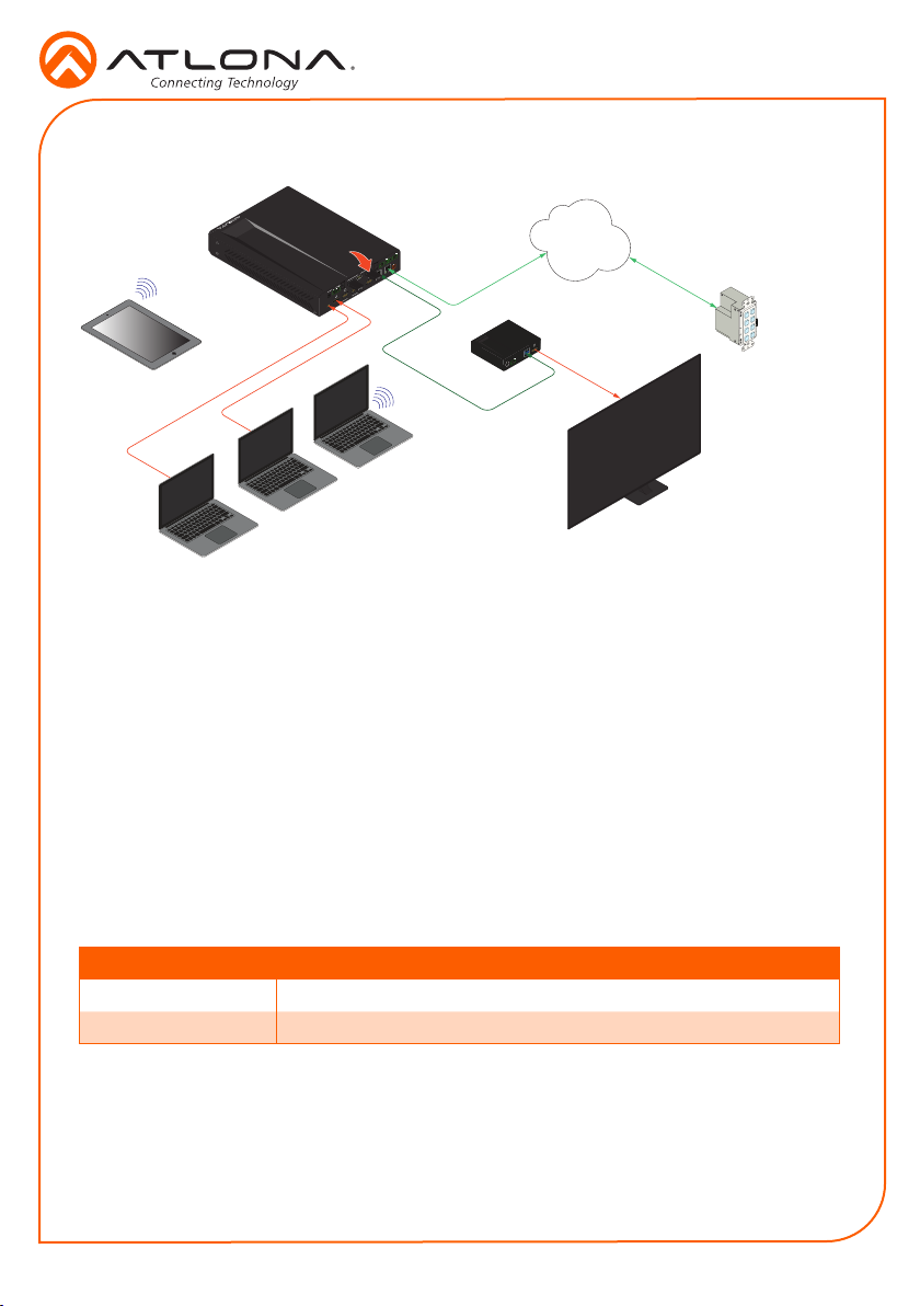
Connection Diagram
Installation Guide
AT-UHD-SW-510W
AT-UHD-SW-510W
Tablet
(BYOD)
Laptop
USB-C
USB Wireless
Antennas
(included)
DisplayPort
Laptop
RS-232
RXP TX
+
TRIGGER I/O
C2
RELAY
COM
C1
+
WiFiWiFi AUX
USB
DC 24V
USB
LAN
USB
USB
HDBaseT OUT
HDMI OUTHDMI IN
+
+
AUDIO
R
OUT
L
3 4
IN
2
DP IN
1
USB-C IN
HDMI
HDBaseT
Miracast™
Laptop
Ethernet
DC 48V RS-232 HDBaseT IN HDMI OUT
AT-UHD-EX-100CE-RX-PSE
RXTX
LAN
Ethernet / PoE
AT-ANC-108D
Network Control Panel
HDMI
UHD/HD Display
IP Conguration
By default, the AT-UHD-SW-510W is set to DHCP mode, allowing a DHCP server (if present) to
assign the unit an IP address. If a DHCP server is not found within 15 seconds, then the unit
will be placed in Auto IP mode and use a self-assigned IP address within the range of 169.254.
xxx.xxx. If DHCP or Auto IP mode are not desired, the unit can be placed into static IP mode by
using the DISPLAY button on the front panel.
Switching the IP mode
Press and hold the INPUT button for approximately 15 seconds. Release the INPUT button. All
the front-panel LED indicators will begin to ash, then the unit will reboot. The number of ashes
will indicate the currently selected IP mode:
LED ashes Description
Two Static IP mode (IP address set to 192.168.1.254)
Four DHCP mode
Once the desired IP mode is set, refer to Obtaining the IP Address, on the next page, for
information on retrieving the IP address of the unit.
9
Page 10

Installation Guide
AT-UHD-SW-510W
Obtaining the IP Address
1. Make sure the unit is powered.
2. Insert a USB drive into the AUX port.
3. Wait approximately 10 seconds.
4. Remove the USB drive and open the text le on a computer.
5. Remove the USB drive and insert the drive into an available USB port on a computer.
6. Two les will be present on the USB drive. One le is formatted for Windows and the other
is formatted for Linux.
Windows: AtlonaReport-Win-GWB-20170821200241.txt
Linux: AtlonaReport-Unix-GWB-20170821200241.txt
7. Double-click the desired le to open it. Information, similar to the following, will be
displayed:
Ethernet #1
IP : 192.168.41.68
MAC : B8:98:B0:05:7E:73
Ethernet #2
IP : 169.254.7.58
MAC : B8:98:B0:05:7E:72
8. The IP address of the AT-UHD-SW-510W is listed under Ethernet #1.
Accessing the webGUI
The AT-UHD-SW-510W includes a built-in webGUI, which allows easy management and control
of all features. Follow the instructions below to access the webGUI.
1. Make sure that an Ethernet cable is connected between the LAN port on the AT-UHD-SW510W and the network.
2. Launch a web browser and enter the IP address of the unit. If the default static IP address
is being used, enter 192.168.1.254.
3. The AT-UHD-SW-510W Login page will be displayed.
4. Enter the following information on the Login page.
Login: admin
Password: Atlona
5. Click the Login button.
6. Refer to User Manual for detailed operation of the webGUI.
NOTE: Refer to the IT Deployment Guide for detailed information on conguring
network modes.
10
Page 11

Troubleshooting
Problem Solution
Installation Guide
AT-UHD-SW-510W
The source image is not
displayed.
Auto-switching is not
working.
The USB-C port is not
charging my USB device.
The AT-UHD-SW-510W is
not controlling the display.
• Check all cable connections between the AT-UHD-SW510W and the source(s) and display.
• Check the input indicators on the front panel to make
sure that the correct input is selected. Press and release
the INPUT button to cycle through each input.
• Try switching to another input to verify all source
connections.
• Check all cable connections between the AT-UHD-SW510W and source devices. If the cable between the
source and the AT-UHD-SW-510W is damaged or is not
secure, then this will prevent auto-switching from working
correctly.
• Verify that audio switching is set to ON, under the
Conguration menu in the webGUI.
• Check that the USB cable is not damaged and provides
a secure connection between the AT-UHD-SW-510W and
the USB device.
• Check the voltage rating of the connected device to
make sure it is compatible. Maximum power and voltage
ratings for the USB-C port are as follows: 60 W at 20 V,
36 W at 12 V, and 15 W at 5 V.
RS-232
• Verify the wiring of the RS-232 captive screw connector.
• Make sure that the proper command syntax is being
used; use an RS-232 terminal emulator to verify the
command.
• Check that the proper baud rate, device ID, control method for the display, and control settings for the AT-UHDSW-510W are correct.
IP
• Make sure that the AT-UHD-SW-510W is on the same
network as the display.
• Ping the display to verify that it is reachable.
• Verify that proper command syntax is being used.
CEC
• Check CEC settings on the display.
• Verify that proper command syntax is being used.
11
Page 12

Installation Guide
AT-UHD-SW-510W
Version 2
atlona.com • 408.962.0515 • 877.536.3976
© 2017 Atlona Inc. All rights reserved. “Atlona” and the Atlona logo are registered trademarks of Atlona Inc. All other brand names and trademarks or registered
trademarks are the property of their respective owners. Pricing, specications and availability subject to change without notice. Actual products, product images, and
online product images may vary from images shown here.
12
 Loading...