

Page 1
Installation Guide
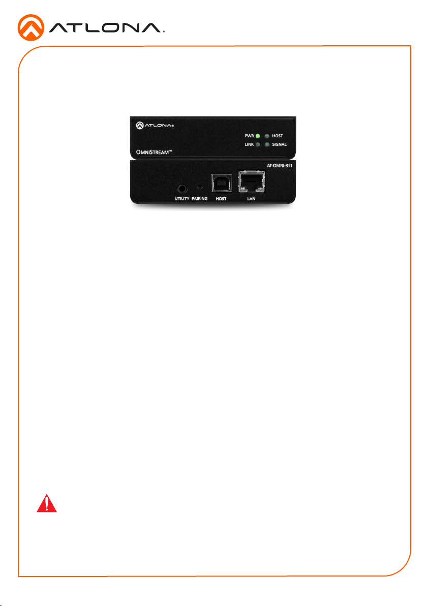
AT-OMNI-311
USB over IP Adapter for Host Device
AT-OMNI-311
The Atlona OmniStream™ USB 311 (AT-OMNI-311) works in tandem with the OmniStream USB
324 (AT-OMNI-324) for extending USB from peripheral devices to a PC over Gigabit Ethernet.
The OmniStream USB 311 interfaces with a PC or other host device, while the OmniStream
USB 324 features a four-port USB hub for peripherals. The OmniStream USB over IP system
is compatible with USB 2.0 data rates of up to 480 Mbps. It can be used with high-bandwidth
devices including cameras, speaker phones, microphones, and DSPs, plus standard USB HID
class devices such as a keyboard, mouse, or touch display. Up to seven OmniStream USB 324
units can be simultaneously paired to an OmniStream USB 311. Additionally, USB routing over
the network can be managed using Atlona Management System (AMS) 2.0.
OmniStream USB products can be used in a wide variety of system design scenarios for soft
codec conferencing and remote keyboard / mouse control. They are ideal for integrating USB
audio and video devices as part of a fully IP-based meeting room system,in conjunction with
OmniStream AV over IP devices and the Velocity Control System.
Package Contents
1 x AT-OMNI-311
2 x Mounting brackets
1 x Installation Guide
IMPORTANT: Visit http://www.atlona.com/product/AT-OMNI-311 for the latest rmware
updates and Installation Guide.
1
Page 2
UTILITY PAIRING LANHOST
AT-OMNI-311
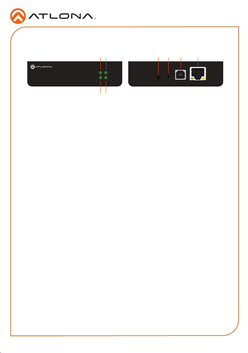
Panel Descriptions
Installation Guide
AT-OMNI-311
Front Rear
PWR
HOST
LINK
OMNISTREAM
TM
SIGNAL
5 6 71 2
UTILITY PAIRING LANHOST
8
3 4
1 PWR
This LED indicator glows solid green when the unit is powered. This unit is powered by the host device
using USB. No external power supply is required. Refer to LED Indicators (page 6) for more
information.
2 HOST
This LED indicator glows green when a USB host device is connected to the unit. Refer to LED
Indicators (page 6) for more information.
3 LINK
This LED indicator is solid green when a solid connection between this unit and the receiver has been
established. Refer to LED Indicators (page 6) for more information.
4 SIGNAL
This LED indicator monitors data transmission between this unit and the receiver. The LED will blink
intermittently whether or not a USB device is connected. Refer to LED Indicators (page 6) for
more information.
5 UTILITY
This port is for factory programming.
6 PAIRING
Press this button to begin the pairing process.
7 HOST
Connect a USB type-B connector from this port to the host computer.
8 LAN
Connect an Ethernet cable from this port to the Local Area Network (LAN).
AT-OMNI-311
2
Page 3

Installation Guide
AT-OMNI-311
Mounting Instructions
The AT-OMNI-311 includes two mounting brackets, which can be used to attach the units to any
at surface.
1. Remove the two enclosure screws, on both sides of the unit, using a small Phillips-head
screwdriver.
HOST
SIGNAL
PWR
LINK
TM
TREAM
S
MNI
O
2. Position one of the mounting brackets, as shown below, aligning
the holes on the side of the enclosure with one set of holes on
the mounting bracket.
3. Attach the mounting brackets using the
enclosure screws from Step 1.
4. Mount the unit using the ovalshaped holes, on each mounting
bracket. If using a drywall
surface, a #6 drywall screw is
recommended.
TM
TREAM
S
MNI
O
HOST
SIGNAL
PWR
LINK
HOST
SIGNAL
PWR
LINK
TM
TREAM
S
MNI
O
NOTE: The unit can also be mounted under a table or other at surface.
3
Page 4

Installation Guide
AT-OMNI-311
Installation
1. Place the AT-OMNI-311 next to the USB host device and connect a USB cable from the
HOST port to the host computer.
The AT-OMNI-311 can be connect to a AT-OMNI-324 (not included) in one of two ways:
Over Network
a. Connect an Ethernet cable, up to 330 feet (100 meters), from the LAN port on the
AT-OMNI-311 to the network switch.
b. Connect an Ethernet cable, up to 330 feet (100 meters), from the receiver (AT-
OMNI-324; not included) to a switch on the same network.
NOTE: When connecting a transmitter and receiver, over a network,
the cable distance between hops must not exceed 330 feet (100 meters)
for copper connections (ber extenders can be used to create longer
runs). For example, connecting up to ve network switches, using copper
cabling, can be used to extend USB up to 1980 feet (600 meters).
Direct Connection
a. Connect an Ethernet cable, up to 330 feet (100 meters), from the LAN port of the
AT-OMNI-311 directly to the AT-OMNI-324 (not included).
2. The AT-OMNI-311 is powered by the host computer. No external power supply is required.
3. Refer to the Installation Guide for the AT-OMNI-324 for additional connection instructions
and the User Manual for detailed information.
4. Refer to Pairing (page 4) for instructions on pairing a transmitter and receiver.
AMS 2.0
For easy conguration of Atlona devices, AMS 2.0 is available from https://atlona.com/AMS for
free. Two options can be used for installation: The free Linux-based software download or the
easy-to-install server hardware (AT-AMS-HW).
Once AMS has been set up:
1. Open a browser on the same network as AMS 2.0 and go to the IP of AMS 2.0. View the
AMS 2.0 installation instructions on how to nd the IP of the software, if necessary.
2. Enter the login information on the AMS 2.0 web page, then click the Login button.
3. View the AT-OMNI-311 manual for additional conguration information.
4
Page 5

Connection Diagram
Microphone
Installation Guide
AT-OMNI-311
Laptop
Laptop
USB
AT-OMNI-311
HOST
SIGNAL
PWR
LINK
TM
TREAM
S
MNI
O
Ethernet
AT-OMNI-324
HOST
SIGNAL
PWR
LINK
TM
TREAM
S
MNI
O
Web-cam
Mouse
Keyboard
Microphone
USB
AT-OMNI-311
HOST
SIGNAL
PWR
LINK
Ethernet
TM
TREAM
S
MNI
O
Ethernet
LAN
Ethernet
Network
Switch
Network
Switch
Ethernet
TREAM
S
MNI
O
AT-OMNI-324
TM
HOST
SIGNAL
PWR
LINK
Web-cam
Mouse
Keyboard
5
Page 6

Installation Guide
AT-OMNI-311
LED Indicators
The PWR, LINK, HOST, and SIGNAL LED indicators on the transmitter provide basic information
on the current status of the AT-OMNI-311. The information in the table below applies to both the
transmitter and receiver unit.
PWR Description
Solid blue Unit is powered.
O Unit is not powered.
• Verify that a USB Type-B cable is connected from the
HOST port to the host computer.
LINK Description
Solid green The link integrity between the transmitter and the receiver is
Blinking green (slow) The transmitter is attempting to establish a link to the receiver.
Blinking green (fast) The transmitter is in Pairing Mode.
O There is no link between the transmitter and the receiver.
HOST Description
Solid green The transmitter is properly enumerated on the host computer.
Blinking green The transmitter is a suspended state.
SIGNAL Description
Blinking green This LED indicator will blink intermittently when data is being
O The transmitter is in Suspend Mode.
good.
• Direct Mode:
Verify that an Ethernet cable is connected between the
LAN port on the sender and the receiver.
• Network Mode:
Verify that an Ethernet cable is connected between the
LAN port on the sender and the network switch.
• Check that the Ethernet cable is not physically damaged.
• Make sure that the Ethernet cable does not exceed 330
feet (100 meters).
transmitted between the transmitter and the receiver.
6
Page 7

Notes
Installation Guide
AT-OMNI-311
7
Page 8

Installation Guide
AT-OMNI-311
Version 1
atlona.com • 408.962.0515 • 877.536.3976
© 2018 Atlona Inc. All rights reserved. “Atlona” and the Atlona logo are registered trademarks of Atlona Inc. All other brand names and trademarks or registered
trademarks are the property of their respective owners. Pricing, specications and availability subject to change without notice. Actual products, product images, and
online product images may vary from images shown here.
8
 Loading...