

Page 1

Installation Guide
AT-OMNI-122
OmniStream 122 Dual-Channel Networked AV Decoder
AT-OMNI-122
The Atlona OmniStream™ 122 (AT-OMNI-122) is a networked AV decoder with two independent
channels of decoding for two OmniStream-encoded video streams up to 4K/UHD, as well as
embedded audio and RS-232 control. OmniStream is designed for distributing AV over Gigabit
Ethernet in enterprises and other large-scale installations. The OmniStream 122 features SMPTE
VC-2 visually lossless compression with extremely low, sub-frame latency, as well as AES128 encryption and SMPTE 2022-5 forward error correction. For professional AV integration, it
includes two HDMI outputs, 4K/UHD scaling for each output with 4:4:4 processing, aspect ratio
control, multi-channel PCM audio downmixing, audio embedding and de-embedding, and more.
This dual-channel decoder is housed in a half rack width enclosure and is ideal for high-density
installations. With two Ethernet ports, the OmniStream 122 can also be integrated with duplicate
AV streams delivered over two networks by the OmniStream 122 dual-channel decoder, for full
system redundancy in mission-critical applications.
Package Contents
1 x AT-OMNI-122
1 x Push spring connector, 6-pin
1 x Captive screw connector, 3-pin
2 x Captive screw connectors, 5-pin
4 x Push spring connectors, 5-pin
1 x Wall/table mounting brackets
4 x Rubber feet
1 x Installation Guide
Operating Notes
• OmniStream requires the Atlona Management System (AMS) which provides discovery,
management, and conguration assistance. AMS is a free application that can be
downloaded from the Atlona web site at http://atlona.com/product/at-sw-ams/
• OmniStream uses mDNS as the discovery mechanism. In order for mDNS to function
properly, there must not be restrictions applied to the network. VPN can be used to
connect to a computer that is running AMS, on the same network. However, VPN cannot
be used when AMS is running on the local machine.
IMPORTANT: Visit http://www.atlona.com/product/AT-OMNI-122 for the latest rmware
updates and User Manual.
1
Page 2
Installation Guide
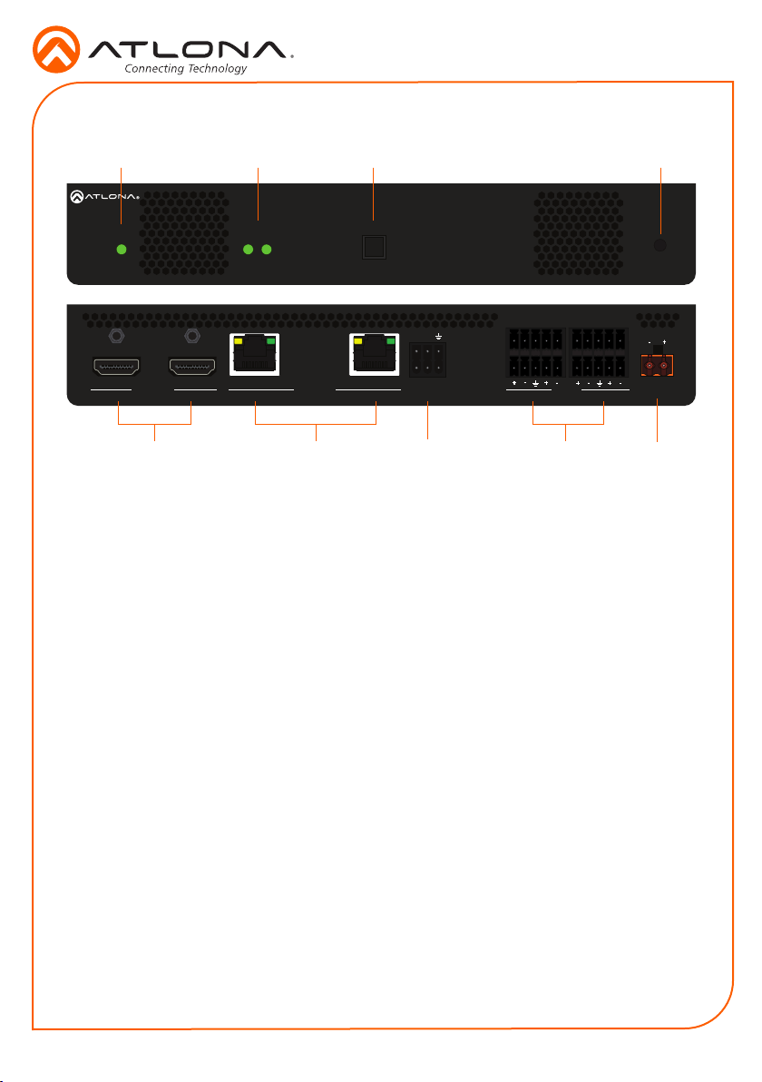
Panel Descriptions
1 2 3 4
AT-OMNI-122
LINK
1 2
1
O
MNISTREAM
AT-OMNI-122
PWR
1
TM
HDMI OUT
2
1 PWR
This LED indicator is green when the unit
is powered.
2 LINK 1 / LINK 2
These LED indicators show the active
input status.
3 ID
Press this button to identify the unit within
the AMS software.
4 REBOOT
Use a pointed object to press this
recessed button and reboot the unit.
5 HDMI OUT
Connect HDMI cables from these ports to
an HD display.
6 ETHERNET 1 / ETHERNET 2
Connect Ethernet cables from these ports
to the Local Area Network (LAN).
ID
TX
RX
1
ETHERNET
2
6 85 9
2
RS-232
7
L1R
IN
OUT
L2R
AUDIO
7 RS-232
Use the included captive screw connector
to connect up to two RS-232 devices to
this port.
8 AUDIO 1 / AUDIO 2
Connect the included push spring
connectors to embed audio on the output
stream and/or connect to an audio output
device. Refer to Audio on page 3 for
more information.
9 DC 48V
Connect the optional 48V DC power
supply to this power receptacle. This
power supply is available, separately,
and is required for embedding and deembedding analog audio.
DC 48V
2
Page 3

Installation Guide
AT-OMNI-122
RS-232
The AT-OMNI-122 provides RS-232 over IP which allows communication between an automation
system and an RS-232 device. This step is optional.
1. Use wire strippers to remove a portion of the cable jacket.
2. Remove at least 3/16” (5 mm) from the insulation of the RX, TX, and GND wires.
3. Insert the TX, RX, and GND wires into correct terminal on the included push spring
connector. If using non-tinned stranded wire, press the orange tab, above the terminal,
while inserting the exposed wire.
NOTE: Typical DB9 connectors use pin 2 for TX, pin 3 for RX, and pin 5 for ground.
On some devices, the function of pins 2 and 3 are reversed.
TX
RX
GND
Audio
Push tab
to unlock
The AT-OMNI-122 provides the ability to embed analog audio on the output stream and output
downmixed 2-channel PCM, using the included captive screw or push spring connectors.
This step is optional.
IMPORTANT: Audio embedding and de-embedding, using the analog audio
outputs, requires the optional OmniStream power supply (AT-PS-48083-C).
• If AUDIO IN or AUDIO OUT will be used, then connect the included 5-pin captive screw
connectors, as shown in the following examples:
R
2
L
R
1
L
IN
TX
1
RX
2
AUDIO
OUT
2-channel analog audio input (top)
DC 48V
1
L
IN
TX
OUT
1
RX
2
2-channel analog audio output (bottom)
R
AUDIO
R
2
L
DC 48V
• If both AUDIO IN and AUDIO OUT ports will be used, then connect the included 5-pin push
spring connectors, as shown on the next page.
3
Page 4

Installation Guide
AT-OMNI-122
Balanced XLR audio
R
2
L
R
1
L
IN
TX
1
RX
2
AUDIO
OUT
DC 48V
1 2
3
+
-
GND GND
Unbalanced XLR audio
1 2
3
-
+
Push tab
to unlock
1 2
3
+
-
GND GND
1 2
3
-
+
If using non-tinned stranded wire, press the orange tab, above the terminal, while inserting
the exposed wire
NOTE: Unbalanced XLR audio requires Pin 1 and Pin 3 to be connected.
The same wiring applies to both captive screw and push spring connectors.
Installation
1. Connect an Ethernet cable from the ETHERNET 1 and ETHERNET 2 ports on the decoder
to a PoE-capable switch on the Local Area Network (LAN). Note that if a PoE-capable
switch is not available, the 48V DC power supply (sold separately) must be connected to the
decoder.
2. Connect HDMI cables from each HD/Ultra HD display to the HDMI OUT ports on the
decoder.
3. If using RS-232, connect the 6-pin captive screw connector to the RS-232 port on the
decoder.
4. The PWR indicator, on the front panel, display the power status of the decoder. When the
decoder is powered, using either PoE or the optional 48V DC power supply (not included),
the LED initially turns red. After a few moments it will turn amber, and nally green.
O
MNISTREAM
PWR
LINK
1 2
TM
ID
PWR indicator
4
Page 5

1
2
HDMIPWR
1
2
LINK DISPLAY INPUT ID
VOLUME
AT-OMNI-112
1
2
HDMIPWR
1
2
LINK DISPLAY INPUT ID
VOLUME
AT-OMNI-112
1
2
HDMI
1
2
LINK DISPLAY INPUT ID
VOLUME
Mounting Instructions
The AT-OMNI-122 decoder includes two
mounting brackets and four mounting screws,
which can be used to attach the unit to any at
surface.
1. Using a small Phillips screwdriver, remove
the two screws from the left side of the
enclosure.
2. Position one of the mounting brackets, as
shown below, aligning the holes on the
side of the enclosure with one set of holes
on the mounting bracket.
3. Use the enclosure screws to secure the
mounting bracket to the enclosure.
Included screws
Installation Guide
5. Repeat steps 1 through 4 to attach the
second mounting bracket to the opposite
side of the unit.
6. Mount the unit using the oval-shaped
holes, on each mounting bracket. If using
a drywall surface, a #6 drywall screw is
recommended.
NOTE: Mounting brackets can
also be inverted to mount the
unit under a table or other at
surface.
PWR
AT-OMNI-112
AT-OMNI-122
4. To provide added stability to the mounting
bracket, use two of the included screws
and attach them to the two holes, directly
below the enclosure screws, as shown
above.
5
Page 6

Installation Guide
AT-OMNI-122
Conguration
By default, the AT-OMNI-122 is set to DHCP mode. In this mode, each decoder that is
connected to the Local Area Network (LAN) will automatically be assigned an IP address by
the DHCP server, allowing communication with AMS. AMS will only be able to discover the
decoders if they are on the same VLAN. Refer to the User Manual for details on conguring
decoders to static IP mode.
To determine the IP address of the decoder, use the Atlona Management System (AMS) app.
AMS is available only for the Windows® Operating Sytem. If necessary, mDNS/Bonjour can also
be used to discover the IP address of the decoder.
1. Launch the Atlona Management System app.
2. Launch a web browser and enter localhost:8080 in the address eld.
3. Enter the login information on the AMS web page, then click the Login button.
Login: admin
Password: admin123
4. Under the Domain View panel, locate the IP address for the decoder. Decoders will be
labeled as OMNI-122.
Connection Diagram
OmniStream 122
Decoder
Video
Automation
NO
COM
NC
2 3 4
NO
COM
NC
1
Control System
NO
COM
NC
NO
COM
NC
GND
+12V
SIG
GND
+12V
SIG
GND
+12V
SIG
GND
+12V
SIG
ETHERNET
L
DIGITAL
R
COAX OUT
Control
COMPONENT
AUDIO OUT AUDIO IN
FACTORY
RESET
48V DC
Ethernet
3
1
4
2
IR OUT
Ethernet
HDMI
VIDEO OUT
SERIAL 1
5
OR
6
SERIAL 2
LAN
Audio
Audio
R
2
AUDIO
R L
1
DC 48V
L
In
TX
RX
Out
RS-232
Eth 2
Eth 1
HDMI OUT
Control
Video
Display
Display
6
Page 7

Troubleshooting
Problem Solution
Installation Guide
AT-OMNI-122
PWR indicator is o. • If using a PoE (Power-over-Ethernet) switch, make
LINK indicator is red. • Connect an Ethernet cable to the ETHERNET port(s).
OmniStream decoders are
not displayed in AMS.
Analog audio embedding/
de-embedding is not
working.
sure that the port on the switch that is connected to
the decoder, has PoE enabled. When the decoder is
powered using PoE, the PWR indicator will be green.
• Check the Ethernet cable for possible damage or loose
connections.
• Connect the optional 48V DC power supply (available
from atlona.com) to the decoder. When using an external
power supply, the PWR indicator will be red.
• Check the Ethernet cable for possible damage or loose
connections.
• Verify that AMS and the decoder are on the same
network.
• If a DHCP server is not found within 60 seconds, the
decoder will be placed in Auto IP mode and assigned
an IP address within the range of 169.254.xxx.xxx. If
so, then connect a laptop directly to the decoder and
congure a static IP address for the decoder.
• Check the Ethernet cable for possible damage or loose
connections.
• The power supply (AT-PS-48083-C) must be connected
to the decoder. Contact Atlona to purchase this power
supply.
7
Page 8

Installation Guide
AT-OMNI-122
Version 2
atlona.com • 408.962.0515 • 877.536.3976
© 2017 Atlona Inc. All rights reserved. “Atlona” and the Atlona logo are registered trademarks of Atlona Inc. All other brand names and trademarks or registered
trademarks are the property of their respective owners. Pricing, specications and availability subject to change without notice. Actual products, product images, and
online product images may vary from images shown here.
8
 Loading...