


Network Enabled
Occupancy Sensor
AT-OCS-900N
Atlona Manuals
Automation

Version Information
Version Release Date Notes
13 Mar 2023 Corrections for hostname specs. Refer to Changing the Hostname (page 17) for
more information.
AT-OCS-900N
2

Sales, Marketing, and Customer Support
Main Oce
Atlona Incorporated
70 Daggett Drive
San Jose, CA 95134
United States
Oce: +1.408.962.0515
Sales and Customer Service Hours
Monday - Friday: 6:00 a.m. - 4:30 p.m. (PST)
https://atlona.com/
Operating Notes
IMPORTANT: Visit https://atlona.com/product/at-ocs-900n/ for the latest rmware updates and
User Manual.
International Headquarters
Atlona International AG
Tdistrasse 18
8002 Zrich
Switzerland
Oce: +41.43.508.4321
Sales and Customer Service Hours
Monday - Friday: 09:00 - 17:00 (UTC +1)
Warranty
To view the product warranty, use the following link or QR code:
https://atlona.com/warranty/.
AT-OCS-900N
3

Safety and Certication
CAUTION
RISK OF ELECTRIC SHOCK
DO NOT OPEN
CAUTION: TO REDUCT THE RISK OF
DO NOT OPEN ENCLOSURE OR EXPOSE
The exclamation point within an equilateral triangle is intended to alert the user to
the presence of important operating and maintenance instructions in the literature
accompanying the product.
The information bubble is intended to alert the user to helpful or optional operational instructions in the literature accompanying the product.
ELECTRIC SHOCK
TO RAIN OR MOISTURE.
NO USER-SERVICEABLE PARTS
INSIDE REFER SERVICING TO
QUALIFIED SERVICE PERSONNEL.
1. Read these instructions.
2. Keep these instructions.
3. Heed all warnings.
4. Follow all instructions.
5. Do not use this product near water.
6. Clean only with a dry cloth.
7. Do not block any ventilation openings. Install in
accordance with the manufacturer’s instructions.
8. Do not install or place this product near any heat
sources such as radiators, heat registers, stoves, or
other apparatus (including ampliers) that produce
heat.
9. Do not defeat the safety purpose of a polarized
or grounding-type plug. A polarized plug has two
blades with one wider than the other. A grounding
type plug has two blades and a third grounding
prong. The wide blade or the third prong are
provided for your safety. If the provided plug does
not t into your outlet, consult an electrician for
replacement of the obsolete outlet.
10. Protect the power cord from being walked on
or pinched particularly at plugs, convenience
receptacles, and the point where they exit from the
product.
11. Only use attachments/accessories specied by
Atlona.
12. To reduce the risk of electric shock and/or damage
to this product, never handle or touch this unit or
power cord if your hands are wet or damp. Do not
expose this product to rain or moisture.
13. Unplug this product during lightning storms or when
unused for long periods of time.
14. Refer all servicing to qualied service personnel.
Servicing is required when the product has been
damaged in any way, such as power-supply cord or
plug is damaged, liquid has been spilled or objects
have fallen into the product, the product has been
exposed to rain or moisture, does not operate
normally, or has been dropped.
FCC Compliance
FCC Compliance and Advisory Statement: This hardware device complies with Part 15 of the FCC rules. Operation is subject to the following two
conditions: 1) this device may not cause harmful interference, and 2) this device must accept any interference received including interference that
may cause undesired operation. This equipment has been tested and found to comply with the limits for a Class A digital device, pursuant to Part
15 of the FCC Rules. These limits are designed to provide reasonable protection against harmful interference in a commercial installation. This
equipment generates, uses, and can radiate radio frequency energy and, if not installed or used in accordance with the instructions, may cause
harmful interference to radio communications. However there is no guarantee that interference will not occur in a particular installation. If this
equipment does cause harmful interference to radio or television reception, which can be determined by turning the equipment o and on, the user
is encouraged to try to correct the interference by one or more of the following measures: 1) reorient or relocate the receiving antenna; 2) increase
the separation between the equipment and the receiver; 3) connect the equipment to an outlet on a circuit dierent from that to which the receiver
is connected; 4) consult the dealer or an experienced radio/TV technician for help. Any changes or modications not expressly approved by the
party responsible for compliance could void the user’s authority to operate the equipment. Where shielded interface cables have been provided
with the product or specied additional components or accessories elsewhere dened to be used with the installation of the product, they must be
used in order to ensure compliance with FCC regulations.
Copyright, Trademark, and Registration
© 2023 Atlona Inc. All rights reserved. “Atlona” and the Atlona logo are registered trademarks of Atlona Inc. Pricing, specications and availability
subject to change without notice. Actual products, product images, and online product images may vary from images shown here.
All other trademark(s), copyright(s), and registered technologies mentioned in this document are the properties of their respective owner(s).
AT-OCS-900N
4

Table of Contents
Introduction 6
Features 6
Package Contents 6
Panel Description 7
Installation 8
Connection Instructions 8
Coverage Pattern Diagrams 9
Removal Instructions 10
Connection Diagram 11
Device Operation 12
Logging in to the Web Server 12
Login Registration 12
Logging in after registration 13
Setting a Static IP Address 14
Using DHCP to assign an IP address 15
Using Transport Layer Security (TLS) 16
Changing the Hostname 17
Resetting Login Credentials 18
Setting Device Information 19
Working with Conguration Files 20
Saving Conguration Files 20
Uploading Conguration Files 20
Resetting the AT-OCS-900N 21
Using the Web Server 21
Using the Hardware Reset Button 21
Restarting the AT-OCS-900N 22
Conguring the Sensor 23
Motion Sensor Events 23
Setting the LED Color 24
Ambient Light Sensor 26
Ambient Temperature Sensor 27
Using MQTT 28
Overview 28
Conguring MQTT 29
Conguration and Management Interfaces 32
Web Server 32
First Time Registration page 32
Login page 33
Dashboard page 34
Sensors Page 38
Protocols Page 41
Network Page 46
User Page 48
System Page 49
Appendix 51
Updating the Firmware 51
Using the Web Server 51
Integration with Velocity 53
Driver Conguration 53
Device Variables 55
Integration with AT-OME-MS52W / AT-UHD-SW-510W 56
Integration with AT-OME-MS42 58
Specications 60
AT-OCS-900N
5

Introduction
The Atlona AT-OCS-900N is a network-enabled multi-function sensor designed for use in a wide variety of AV
automation applications. This ceiling mounted sensor uses passive infrared (PIR) technology to detect occupancy
in the coverage area. The OCS-900N utilizes an IP network to communicate with select Atlona products and the
Velocity™ system to automatically control AV components based on whether the space is occupied. It comes with
two lenses that cover approximately 900 or 2,000 square feet depending on ceiling height. A blinder insert is included
that limits the sensor’s eld of view, preventing detection in unwanted areas such as doorways or windows with
heavy cross trac. Installation is simplied by Power over Ethernet (PoE), that provides both communications and
power over a single cable as well as spring-loaded clamps that secure the sensor to a ceiling tile.
In addition to occupancy, the OCS-900N also captures temperature and ambient light level information. Its open
standard design allows sensor information to be communicated to third-party ventilation, lighting, and other systems
over TCP/IP using common protocols such as UDP, TCP, WebSocket, and MQTT.
Features
• Multi-function sensor that detects occupancy, temperature, and ambient light.
• IP-enabled for communicating state information over Ethernet.
• Passive infrared (PIR) detection technology.
• Customizable detection area with standard lens covering 900 square feet and included accessory lens covering
2,000 square feet.
• 360 degrees eld of view standard, or limit to 240 degrees with included blinder insert.
• Congurable LED indicators may be customized for both color and activity.
• Communicates over the network directly to the Atlona AT-WAVE-101 for automatic display control.
• Works with Velocity™ AV control systems for more complex automation applications.
• Supports network communications with third-party devices using common protocols such as UDP, TCP,
WebSocket, and MQTT.
• Power over Ethernet (PoE) for remote power and network connection with a single cable.
Package Contents
1 x AT-OCS-900N with installed Standard Ceiling lens
1 x 120-degree optics shader
1 x High Ceiling lens
1 x Installation guide
AT-OCS-900N
6

Panel Description
Energy Mgmt Equip
Motion Sensor - Low Bay, White
Connect to LPS supply only
Input: 57V, 1.4W, Max Amb: 50° C
S/N: 210226-IDLM-XX1
MAC: 68-27-19-D2_2E-CE
AT-OCS-900N 210226-1
1
2 2 2 4
3
2
Top (cover/lens removed)
1 Fresnel Lens
Diracts the incoming light and directs the light to the
infrared sensor.
2 LED indicators
These indicators provide lens illumination for device
functionality and testing. These LED indicators can
be changed to dierent colors, if desired. Refer
to Setting the LED Color (page 24) for more
information.
Top
Bottom
3 Factory Reset
Press and hold this button for 5 seconds to reset the
AT-OCS-900N to factory-default settings. Refer to
Resetting the AT-OCS-900N (page 21) for more
information.
4 LAN port
Connect an Ethernet cable from this port to the Local
Area Network.
AT-OCS-900N
7
Installation
Energy Mgmt Equip
Motion Sensor - Low Bay, White
Connect to LPS supply only
Input: 57V, 1.4W, Max Amb: 50° C
S/N: 210226-IDLM-XX1
MAC: 68-27-19-D2_2E-CE
AT-OCS-900N 210226-1
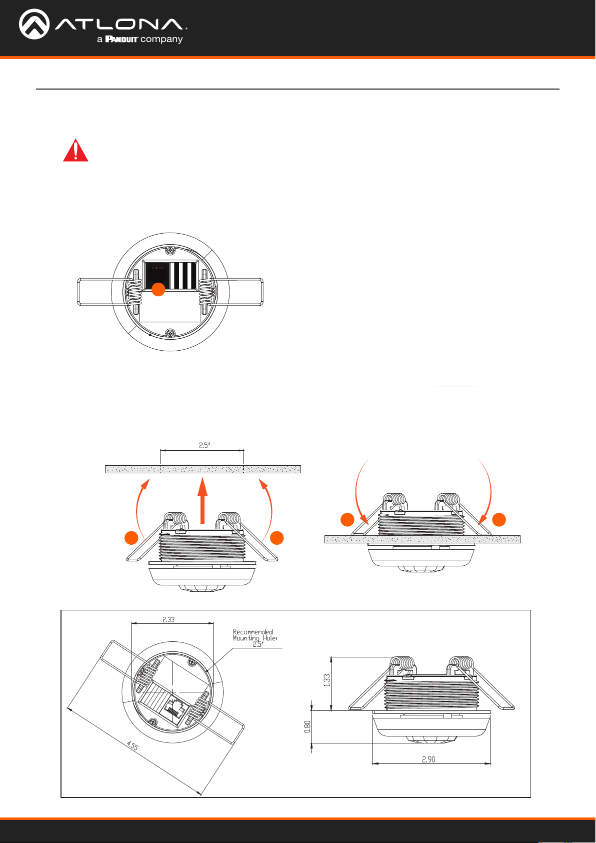
Connection Instructions
IMPORTANT: This product is designed to be installed by instructed or skilled person(s) only.
Also, do not touch or apply pressure to the IR sensor. Doing so may damage or break the IR
sensor.
1. Determine the coverage area required. Refer to Coverage Pattern Diagrams (page 9) for more information.
2. Connect an Ethernet cable from the LAN port to the Local Area Network.
2
3. In a pre-drilled 2.5” hole, fold the wing clips towards the center of the AT-OCS-900N. The recommended
mounting hold diameter is 2.5” and should not exceed a diameter of 2.90”. Refer to Figure 1.1 for dimensions of
the AT-OCS-900N.
4. Insert the device into the ceiling tile and release clips. The wing clips will return to the down position, securing
the unit in place.
C E I L I N G
4 4
3 3
C E I L I N G
Figure 1.1
AT-OCS-900N
8

(18.3 m)
Installation
Coverage Pattern Diagrams
The AT-OCS-900N includes a factory-installed Standard Ceiling lens. The Standard Ceiling lens can be replaced with
the included High Ceiling lens, depending on the size of the room. Refer to the diagrams below for coverage area.
Standard Ceiling Coverage High Ceiling Coverage
Top View
15 ft
(4.6 m)
10 ft
(3.0 m)
5 ft
(1.5 m)
0
5 ft
(1.5 m)
10 ft
(3.0 m)
15 ft
(4.6 m)
Top View
60 ft
(18.3 m)
40 ft
(12.2 m)
20 ft
(6.1 m)
0
20 ft
(6.1 m)
40 ft
(12.2 m)
60 ft
Side View Side View
(2.4 m)
10 ft
(3.0 m)
12 ft
(3.7 m)
0
0
20 ft
(6.1 m)
8 ft
20 ft
15 ft
10 ft
(6.1 m)
(4.6 m)
(3.0 m)
(1.5 m)
5 ft
0
(1.5 m)
10 ft
5 ft
(3.0 m)
15 ft
(4.6 m)
20 ft
(6.1 m)
30 ft
(9.1 m)
40 ft
(12.2 m)
40 ft
(12.2 m)
30 ft
(9.1 m)
20 ft
(6.1 m)
10 ft
(3.0 m)
0 10 ft
(3.0 m)
20 ft
(6.1 m)
30 ft
(9.1 m)
40 ft
(12.2 m)
AT-OCS-900N
9
Installation
Energy Mgmt Equip
Motion Sensor - Low Bay, White
Connect to LPS supply only
Input: 57V, 1.4W, Max Amb: 50° C
S/N: 210226-IDLM-XX1
MAC: 68-27-19-D2_2E-CE
AT-OCS-900N 210226-1
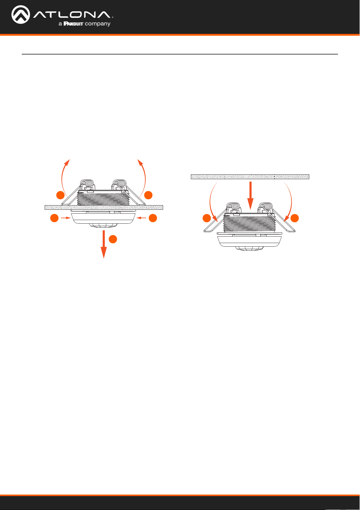
Removal Instructions
The AT-OCS-900N can be easily removed if necessary. Refer to the instructions below.
1. Gently grasp the AT-OCS-900N by the lens cover and slowly pull down with steady pressure.
2. As the unit pulled down, the wing clips will fold up, allowing the unit to be removed from the mounting hole.
3. Once the removed, the wing clips will return to their normal position.
4. Disconnect the Ethernet cable from the LAN port.
C E I L I N G
2
C E I L I N G
1 1
1
2
3 3
AT-OCS-900N
10

Connection Diagram
Installation
AT-OCS-900N
11
Device Operation
Logging in to the Web Server
Most of the AT-OCS-900N operation is handled through the built-in web server. In order to access the web server,
the IP address of the unit must be known.
Login Registration
1. Launch the desired web browser and enter the IP address of the AT-OCS-900N in the address bar.
2. The AT-OCS-900N Login Registration page will be displayed.
3. Enter the desired username in the Username eld. In the example above, the username admin is used.
4. Enter the desired password in the Password eld.
IMPORTANT: Both the username and password must be 5 - 16 characters in length. Alphanumeric
characters and symbols are permitted. Note that the Password eld will be masked when entering
the password.
5. Verify the password by entering it in the Conrm eld.
6. Click the Register button.
7. The Dashboard screen will be displayed. Refer to Dashboard page (page 34) for more information.
8. The login registration process is complete.
AT-OCS-900N
12

Device Operation
Logging in after registration
1. Launch the desired web browser and enter the IP address of the AT-OCS-900N in the address bar.
2. Enter the correct username and password in the respective elds.
3. Click the Login button.
4. The Dashboard page will be displayed. Refer to Dashboard page (page 34) for more information.
AT-OCS-900N
13
Setting a Static IP Address
1. Open the desired web browser and enter the IP address of the AT-OCS-900N.
2. Login using the required credentials.
3. Click Network on the side menu bar.
Device Operation
4. Locate Enable DHCP. If there is a check mark in this box, click to remove the check mark. This will disable
DHCP and provide the option to specify a static IP address.
5. Enter the desired address in the IP Address eld. Also enter the required information in the Gateway and
Subnet Mask elds.
6. Enter DNS information in the Primary DNS and Secondary DNS elds, if required.
7. Click the Restart Device button to save the changes and restart the unit using the static IP address.
AT-OCS-900N
14

Device Operation
Using DHCP to assign an IP address
The AT-OCS-900N is shipped with DHCP enabled. Once connected to a network, the DHCP server (if available),
will automatically assign an IP address to the unit. To switch from a static IP address to a dynamically-assigned IP
address, DHCP must be enabled on the AT-OCS-900N.
1. Open the desired web browser and enter the IP address of the AT-OCS-900N.
2. Login using the required credentials.
3. Click Network on the side menu bar.
4. Click the Enable DHCP checkbox. If the box is checked, then the AT-OCS-900N will obtain an IP address from a
DHCP server.
NOTE: When Enable DHCP is active, none of the IP address elds can be changed.
5. Click the Restart Device button to save changes and restart the unit.
AT-OCS-900N
15

Device Operation
Using Transport Layer Security (TLS)
The AT-OCS-900N provides Transport Layer Security (TLS) for added communication security over a non-secure
network. TLS is enabled by default on the AT-OCS-900N. However, this feature can be enabled or disabled.
Enabling TLS is required if using MQTT over TLS.
1. Open the desired web browser and enter the IP address of the AT-OCS-900N.
2. Login using the required credentials.
3. Click Network on the side menu bar.
4. Locate the Enable TLS checkbox. When checked, TLS is enabled. Uncheck this box to disable TLS.
5. Click the Restart Device button to save changes and restart the unit.
AT-OCS-900N
16

Device Operation
Changing the Hostname
By default, the host name of the AT-OCS-900N is set to the following: OCS-900N-[id], where [id] is the last
six digits of the MAC address. However, the host name can be changed to a more recognizable identier.
The hostname must conform to the NetBIOS specication.
1. Open the desired web browser and enter the IP address of the AT-OCS-900N.
2. Login using the required credentials.
3. Click Network on the side menu bar.
4. Click in the Host Name eld and enter the desired host name.
5. Click the Restart Device button to save changes and restart the unit.
AT-OCS-900N
17

Device Operation
Resetting Login Credentials
It is recommend to change the login credentials often to restrict access to the AT-OCS-900N by authorized users.
Both the user name and password can be changed.
1. Open the desired web browser and enter the IP address of the AT-OCS-900N.
2. Login using the required credentials.
3. Click User in the side menu bar.
Log Out button
4. In the Username eld, enter the desired user name.
5. In the New Password eld, enter the desired password.
NOTE: Both the user name and password must be 5 - 16 characters in length, and can be any
combination of letters, numbers, and symbols. Spaces are not permitted.
6. Click the Save button to commit changes.
7. Click the Log Out button in the upper-right corner of the web server, then log in using the new credentials.
AT-OCS-900N
18

Device Operation
Setting Device Information
The AT-OCS-900N can be assigned a name a location for reference. This information is optional, but can be useful to
identify multiple AT-OCS-900N units. Name and location information will be displayed under the Dashboard menu.
1. Open the desired web browser and enter the IP address of the AT-OCS-900N.
2. Login using the required credentials.
3. Click System in the side menu bar and locate the System Settings window group.
4. In the Name eld, enter the desired name of the AT-OCS-900N.
5. In the Location eld, provide a description of where the AT-OCS-900N is installed.
6. Click the Save button to commit changes.
AT-OCS-900N
19

Device Operation
Working with Conguration Files
AT-OCS-900N settings can be saved to or loaded from a local le. It is recommended to save the device settings,
once the unit is properly congured. Conguration les are stored in .json format.
Saving Conguration Files
1. Open the desired web browser and enter the IP address of the AT-OCS-900N.
2. Login using the required credentials.
3. Click System in the side menu bar.
4. Locate the Congure Settings window group and click the Download button.
5. The Save As window dialog will be displayed.
6. Select the desired location to store the conguration le and click the Save button.
7. Enter the name of the le in the Filename eld. The default lename is cong.json.
Uploading Conguration Files
1. Follow steps 1 - 3 above.
2. Locate the Congure Settings window group and click the Choose File button.
3. The Open dialog will be displayed.
4. Select the desired conguration le and click Open.
5. Click the Upload button to upload the selected le to the AT-OCS-900N.
AT-OCS-900N
20

Device Operation
Energy Mgmt Equip
Motion Sensor - Low Bay, White
Connect to LPS supply only
Input: 57V, 1.4W, Max Amb: 50° C
S/N: 210226-IDLM-XX1
MAC: 68-27-19-D2_2E-CE
AT-OCS-900N 210226-1
Resetting the AT-OCS-900N
When the AT-OCS-900N is reset, the unit will be set to factory-default settings. Before performing a reset, it is
recommended to save the current settings to an external le. Refer to Working with Conguration Files (page 20)
for more information.
IMPORTANT: Resetting the AT-OCS-900N will restore the unit to factory settings. All settings will be
lost!
Using the Web Server
1. Open the desired web browser and enter the IP address of the AT-OCS-900N.
2. Login using the required credentials.
3. Click System in the side menu bar.
4. Locate the Sensor Actions window group and click the Factory Reset button.
Using the Hardware Reset Button
If access to the web server is not available, the AT-OCS-900N provides a reset button on the unit.
1. Remove the lens cap by rotating it counterclockwise.
2. Locate the square-shaped Factory Reset button, near the center of
the unit.
3. Press and hold the button for 5 seconds to factory-reset the unit.
4. Replace the lens cap on the unit by turning clockwise.
AT-OCS-900N
2
21

Device Operation
Restarting the AT-OCS-900N
The AT-OCS-900N can be restarted without losing any settings. Following the procedure below.
1. Open the desired web browser and enter the IP address of the AT-OCS-900N.
2. Login using the required credentials.
3. Click System in the side menu bar.
4. Locate the Sensor Actions window group and click the Restart Device button.
AT-OCS-900N
22

Conguring the Sensor
This section covers the sensor conguration and LED indicator color modication.
Motion Sensor Events
1. Open the desired web browser and enter the IP address of the AT-OCS-900N.
2. Login using the required credentials.
3. Click Sensors in the side menu bar.
4. Locate the Motion Sensors window group.
Device Operation
5. In the Motion On Event eld, enter the period of continuous motion (in seconds) that is required before the
motion-on event is triggered.
6. In the Motion O Event eld, enter the delay (in minutes) in which there is no motion, before the motion-o event
is triggered.
7. Click the Save button, in the lower-right corner of the Motion Sensor window group, to commit changes.
AT-OCS-900N
23

Device Operation
Energy Mgmt Equip
Motion Sensor - Low Bay, White
Connect to LPS supply only
Input: 57V, 1.4W, Max Amb: 50° C
S/N: 210226-IDLM-XX1
MAC: 68-27-19-D2_2E-CE
AT-OCS-900N 210226-1
Setting the LED Color
The AT-OCS-900N has a single center and three outer LED indicators, as shown below. Removing the lens cap will
expose these LED indicators. The color of each of these LED indicators can be changed to any color. Note that
when these LED indicators are triggered, either the center or outer indicators will be triggered. Both center and outer
LED indicators cannot be triggered at the same time.
2
2
(1) Center LED
(2) Outer LED
1
2
1. Open the desired web browser and enter the IP address of the AT-OCS-900N.
2. Login using the required credentials.
3. Click Sensors in the side menu bar.
4. Locate the LED Indicator window group.
5. Click the Illumination Location drop-down list to select either Center or Outer.
AT-OCS-900N
24
Device Operation
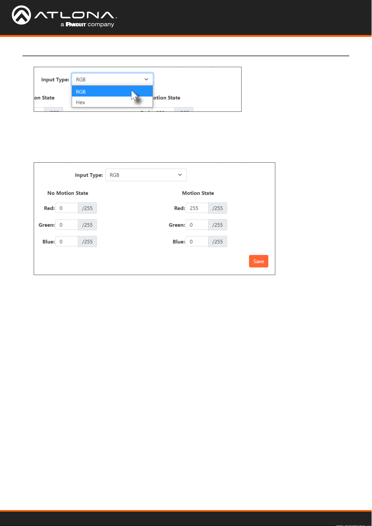
6. Click the Input Type drop-down list and select RGB or Hex. If RGB is selected, the LED color will be
represented by Red, Blue, Green (RGB) values. The valid range for each component is 0 to 255. If Hex is
selected, then the LED color will be represented by a singular hexadecimal value in the form of #xxxxxx. Valid
range is #000000 to #FFFFFF.
7. Enter the value(s) for both the No Motion State and Motion State, depending on the color format that was
selected in the previous step.
8. Click the Save button to commit changes.
AT-OCS-900N
25

Ambient Light Sensor
This section provides adjustment for ambient light sensitivity.
1. Open the desired web browser and enter the IP address of the AT-OCS-900N.
2. Login using the required credentials.
3. Click Sensors in the side menu bar.
4. Locate the Ambient Light Sensor window group.
Device Operation
5. Click the Sensitivity drop-down list and select the desired setting. For brighter environments, set the sensitivity
setting to a lower value. For darker environments, set the sensitivity setting to a higher value.
6. Under Events, enter the sensor communication threshold in the provided eld. This value will be the minimum
value required to trigger an event.
7. Click the Save button to commit changes.
AT-OCS-900N
26

Device Operation
Ambient Temperature Sensor
This section provides adjustment for ambient light sensitivity.
1. Open the desired web browser and enter the IP address of the AT-OCS-900N.
2. Login using the required credentials.
3. Click Sensors in the side menu bar.
4. Locate the Ambient Temperature Sensor window group. The current ambient temperature will be displayed.
5. In the provided eld, enter the change in temperature when an event should be triggered. Click the drop-down
list next to this eld to select either °F or °C.
6. Click the Save button to commit changes.
AT-OCS-900N
27

Device Operation
Using MQTT
Overview
The term Internet of Things (IoT) is used to describe devices that connect and exchange data with other devices and
systems over the Internet or other local networks. However, in order for each device to be able to communicate with
one another, a communication protocol must be used. One such protocol is Message Queuing Telemetry Transport
(MQTT) and is used by the AT-OCS-900N to communicate with other devices. MQTT is a TCP-based “subscribe and
publish” protocol. A detailed explanation of the MQTT protocol is beyond the scope of this manual. However, the
illustration below shows the basic architecture.
The MQTT architecture consists of a broker (server) and one or more clients. For example. in the Figure 1.2, the
AT-OCS-900N is connected to a LAN, along with two other clients and a broker. Client A and Client B will now
subscribe to a particular topic, which is then published to the broker. A topic can be anything, but for this illustration,
Client A and Client B will subscribe to the “temperature” topic.
Figure 1.2
Client A
Client B
MQ Broker (Server)
Ethernet
Topic: temperature
Ethernet
Topic: temperature
LAN
Ethernet
Topic: temperature
Ethernet
Topic: temperature
AT-OCS-900N
When the AT-OCS-900N updates the topic of “temperature”, it will publish this information to the topic of
“temperature” to the broker. Since both Client A and Client B are subscribing to the topic of “temperature”,
both Client A and Client B will receive the updated temperature information.
AT-OCS-900N
28
Device Operation
Conguring MQTT
This section provides instructions on conguring MQTT.
1. Open the desired web browser and enter the IP address of the AT-OCS-900N.
2. Login using the required credentials.
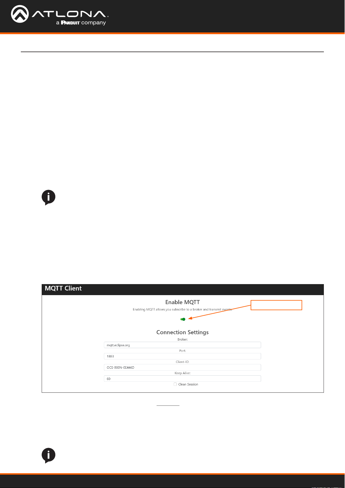
3. Click Protocols in the side menu bar and locate the MQTT Client window group.
4. Click the Enable MQTT toggle switch to enable the feature. When enabled, this toggle switch will be green.
5. Under Connection Settings, do the following:
a. Enter the address of the broker in the Broker eld.
b. Enter the port number in the Port eld. The default non-secure port is 1883, as shown below. However, if
using MQTT over TLS, then port 8883 must be used.
NOTE: If using MQTT over TLS, then Transport Layer Security (TLS) must be enabled. To enable
TLS, click the Network menu and click the checkbox for Enable TLS. Refer to Using Transport
Layer Security (TLS) (page 16) for more information.
c. Enter the client name in the Client-ID eld. This eld is required in order for the broker to store session
information for a client.
d. Enter the keep alive value in the Keep Alive eld. This value is used to make sure that the connection
between the broker and the client are open and that both devices are aware of being connected. Setting this
value to 0 (zero) will disable the keep alive mechanism.
e. Click the Clean Session checkbox to enable to disable a clean (non-persistent) session. When enabled, this
box will be checked.
MQTT toggle switch
When Clean Session is enabled, the broker does not store subscription information or any undelivered
messages for the client device. All information is purged from any previous persistent connection. This
mode should be used when the client only publishes messages.
Clean Session can also be disabled (referred to as a persistent connection or durable connection). In this
mode, the broker will store both subscription and undelivered messages for the client.
AT-OCS-900N
NOTE: All messages are deleted from the broker once they have been delivered to the client.
29

6. Under Authentication Settings do the following:
a. Enter the required information in the Username and Password elds. When a client connects to a
broker, both the user name and password are included in the CONNECT message for authentication
purposes. It should be noted that authentication is optional and only required if the broker requires
authentication.
b. To enable authentication, click the Authentication checkbox. When a checkmark is in this box, the
feature is enabled.
IMPORTANT: Authentication credentials are not automatically encrypted when transmitted to
the broker, making the information vulnerable to a MITM attack. It is highly recommended to
use Transport Layer Security (TLS) when connecting to a broker. Refer to Using Transport Layer
Security (TLS) (page 16) for more information.
Device Operation
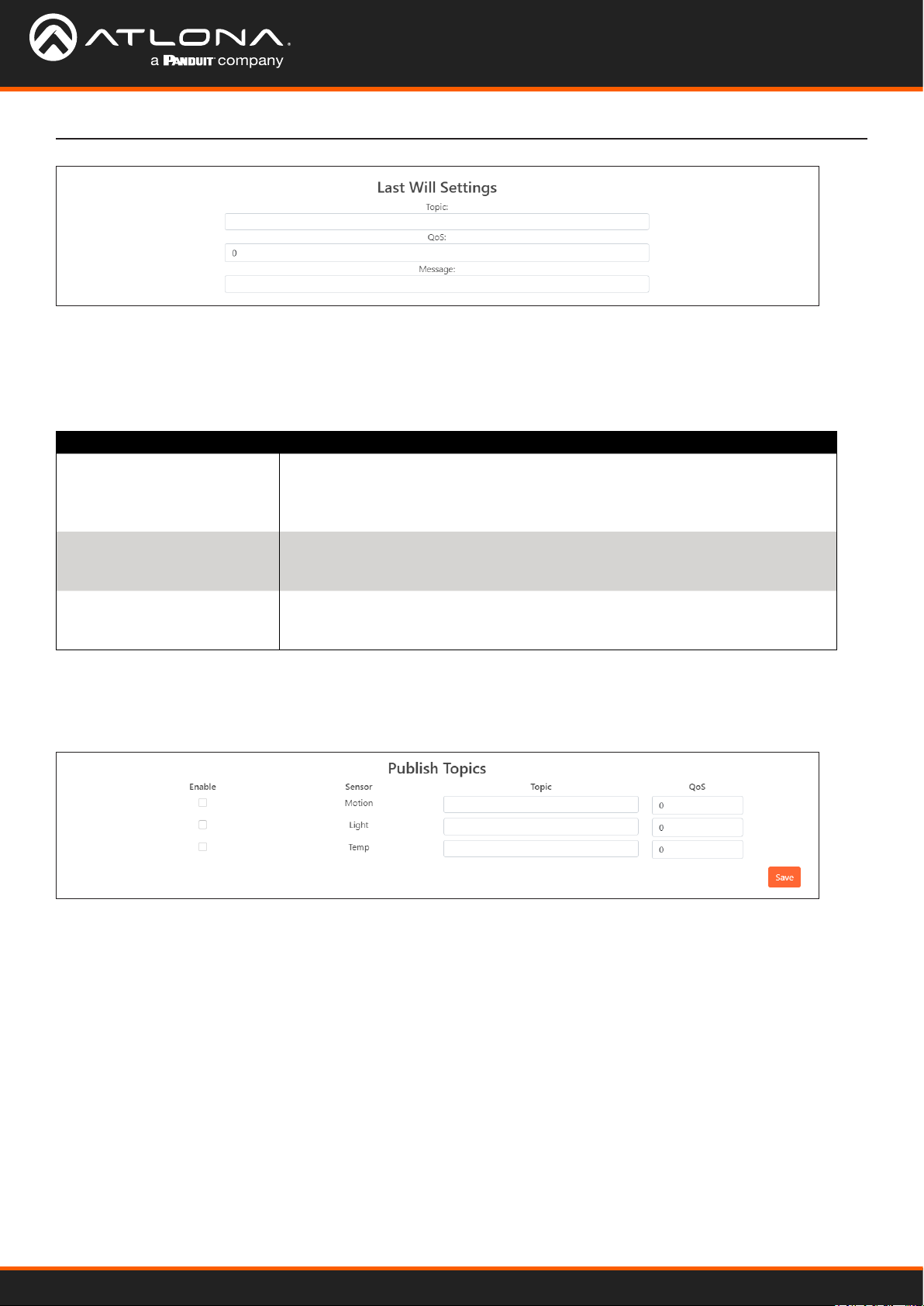
7. Under Last Will Settings do the following:
a. Enter the Last Will and Testament (LWT) topic in this Topic eld. This topic is sent to other clients when a
client does not disconnect gracefully. An example topic might be /client1/status.
b. Click the QoS eld to select the desired Quality of Service setting.
QoS Setting Description
0 At most once - Guarantees a best-eort delivery. It functions similar
1 At least once - Guarantees that a message is delivered at least once
2 Exactly once - The highest level of service and guarantees that
c. Enter the message in the Message eld.
to the UDP protocol, where there is no guarantee of delivery from the
client to the broker. The recipient does not acknowledge receipt of
the message and the message is not stored and re-transmitted by the
sender.
to the receiver. The sender stores the message until it receives a
PUBACK packet from the receiver that acknowledges receipt of the
message.
each message is received only once by the intended recipients. The
guarantee is provided by at least two request/responses between the
sender and the receiver.
AT-OCS-900N
30

8. The nal section is the Publish Topics section:
a. Click the Enable checkboxes in each row to enable topic publication. The Sensor column identies the
sensor role for each topic. These identiers cannot be changed.
b. Enter the desired topic in the Topic elds. An example for Motion might be building/conf1/door.
c. Click the QoS eld to select the desired Quality of Service setting.
QoS Setting Description
0 At most once - Guarantees a best-eort delivery. It functions similar
to the UDP protocol, where there is no guarantee of delivery from the
client to the broker. The recipient does not acknowledge receipt of
the message and the message is not stored and re-transmitted by the
sender.
1 At least once - Guarantees that a message is delivered at least once
to the receiver. The sender stores the message until it receives a
PUBACK packet from the receiver that acknowledges receipt of the
message.
2 Exactly once - The highest level of service and guarantees that
each message is received only once by the intended recipients. The
guarantee is provided by at least two request/responses between the
sender and the receiver.
Device Operation
9. Click the Save button to commit changes.
AT-OCS-900N
31

Conguration and Management Interfaces
Web Server
The AT-OCS-900N includes a built-in web server. The web server is used for conguration and modication of the
AT-OCS-900N operation. Refer to Logging in to the Web Server (page 12) for more information on accessing the
web server.
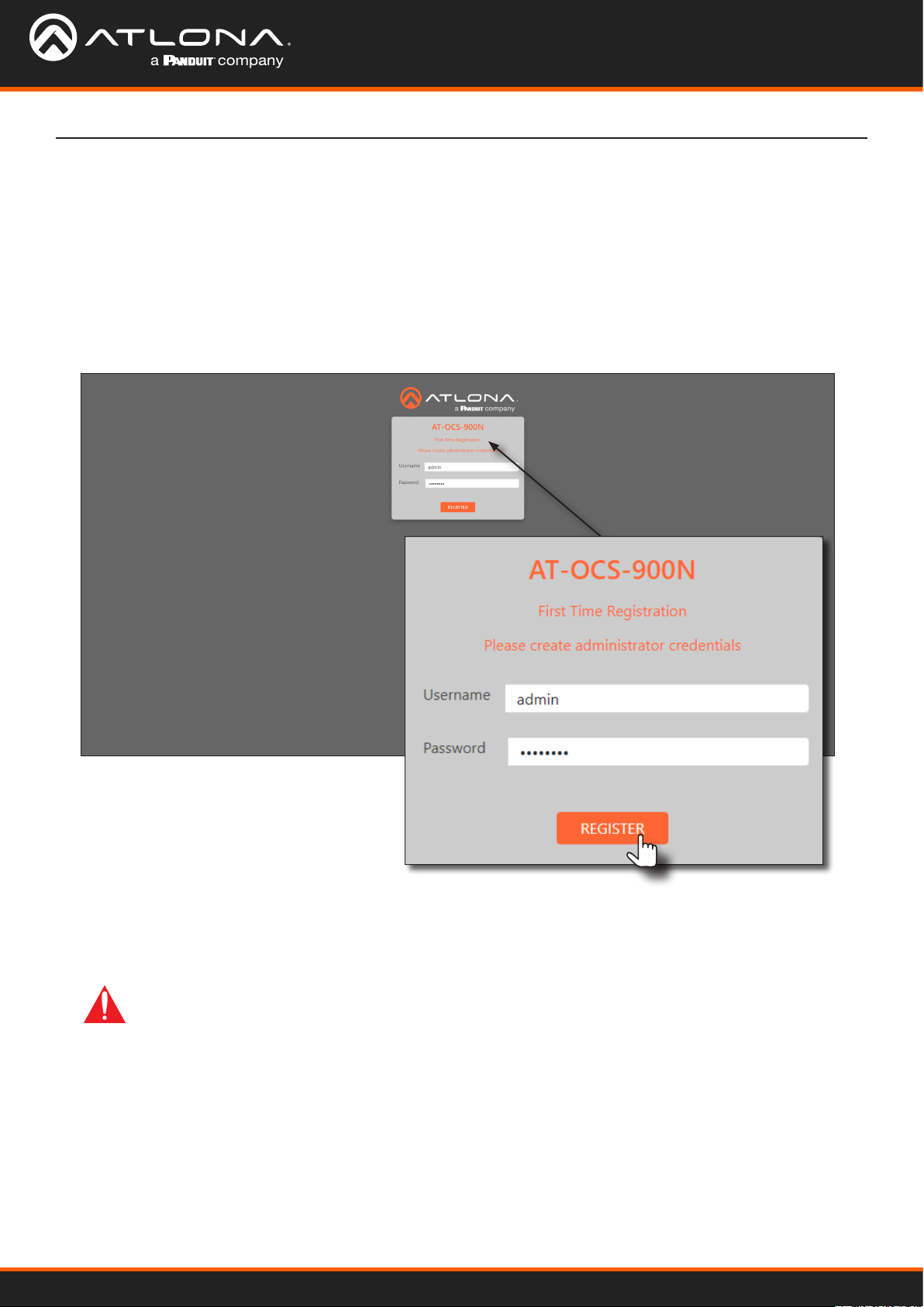
First Time Registration page
This page is displayed when the AT-OCS-900N web server is launched for the rst time.
Username
Enter the desired username in this eld. The username must be 5 - 16 characters in length, and can be any
combination of letters, numbers, and symbols. Spaces are not permitted.
Password
Enter the desired password in this eld. The password must be 5 - 16 characters in length, and can be any
combination of letters, numbers, and symbols. Spaces are not permitted.
Register
Click this button to register the username and password with the AT-OCS-900N.
AT-OCS-900N
32

Conguration and Management Interfaces
Login page
This page is displayed when the IP address of the AT-OCS-900N is entered in the address bar of a web browser.
Username
Enter the username in this eld.
Password
Enter the password in this eld.
Login
Click this button to login.
AT-OCS-900N
33

Conguration and Management Interfaces
Dashboard page
After logging in, the Dashboard page will be displayed. This page provides basic information about the unit,
including the model name, software version, and IP address information.
Device Info
Model Name
The model SKU of this product.
Hardware #
The hardware version.
Serial Number
The serial number of the unit.
Firmware Version
The version of rmware that the AT-OCS-900N is running. Always make sure to check the AT-OCS-900N product
page on the Atlona web site for the latest version of rmware.
Up Time
The time elapsed since the unit was powered on. Format is days, hours, minutes, and seconds.
AT-OCS-900N
34

Conguration and Management Interfaces
System Info
Both of these elds can be modied under the System menu. Refer to Setting Device Information (page 19) for
more information.
Name
The name of the AT-OCS-900N.
Location
The location of the AT-OCS-900N.
Network Info
All of the following elds can be modied under the Network menu.
IP Address
The IP address of the AT-OCS-900N.
Netmask
The subnet mask of the unit.
Gateway
The default gateway (router) for the network.
Hostname
The hostname of the unit. Refer to Changing the Hostname (page 17) for more information.
MAC
The Media Access Control (MAC) address of the AT-OCS-900N.
DNS 1 / DNS 2
The address of the DNS servers.
AT-OCS-900N
35
Conguration and Management Interfaces
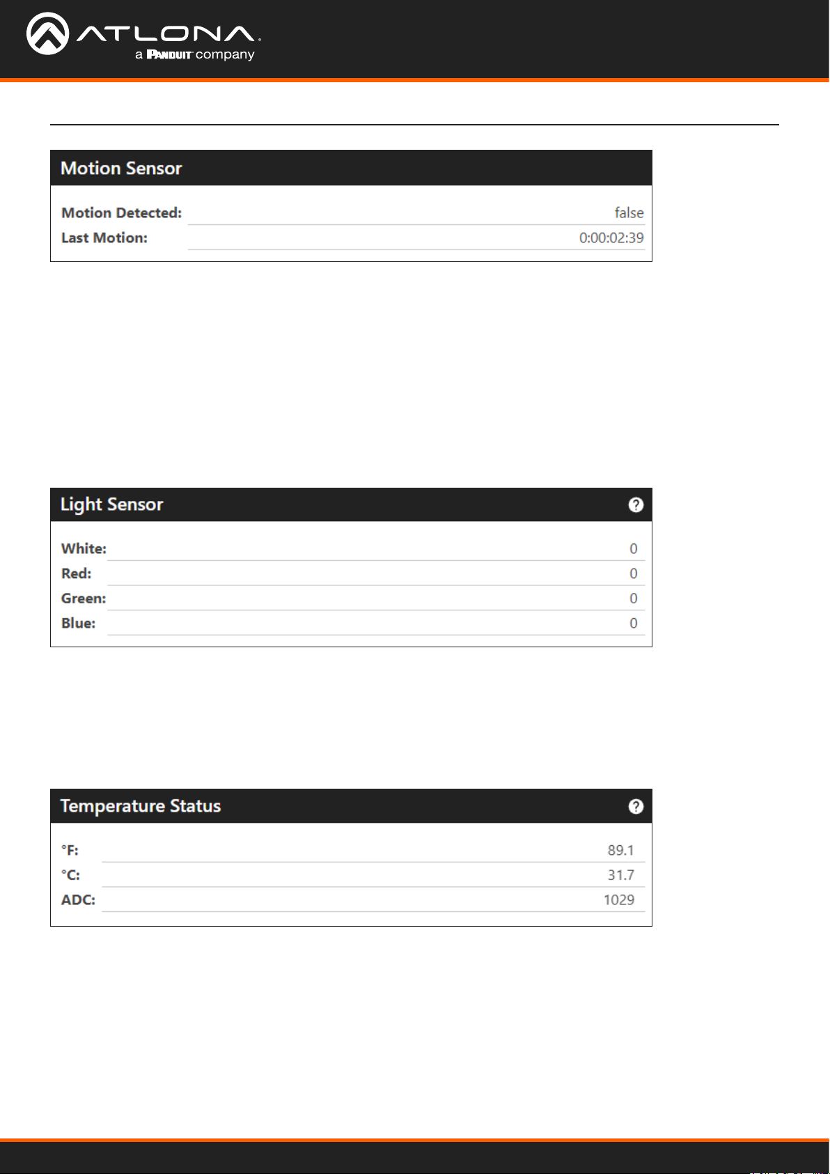
Motion Sensor
Motion Detected
Indicates if the AT-OCS-900N has detected movement within the area. Possible values: true, false.
Last Motion
Displays the time of the last-detected motion since the unit was powered on. If there is constant motion being
detected, this clock will continue to run until movement is no longer detected. Time format is in days, hours,
minutes, and seconds.
Light Sensor
White, Red, Green, Blue
These values display the values of the individual color components of the ambient light.
Temperature Status
°F, °C, ADC
Displays the temperature in the associated units.
AT-OCS-900N
36

Conguration and Management Interfaces
LED Indicator
Red, Green, Blue
Displays the current color of the LED indicators. These values can be changed. Refer to Setting the LED Color (page
24) for more information.
Protocols
UDP, TCP, WS, MQTT
Each of these toggle switches provide quick enabling/disabling of these protocols. If a protocol is enabled, the
toggle switch will be displayed in green. Refer to Protocols Page (page 41) for more information.
AT-OCS-900N
37

Conguration and Management Interfaces
Sensors Page
The Sensors page provides controls to adjust sensitivity and triggering.
Motion Sensor
Motion On Event
Sets the time period (in seconds) where continuous motion must be detected, before the event is triggered. Valid
ranges are integers from 0 to 120.
Motion O Event
Sets the time period (in minutes) where no motion must be detected, before the event is triggered. The Motion O
Event is also referred to as debounce. Valid ranges are integers from 0 to 120.
Save
Click this button to commit changes.
AT-OCS-900N
38

Conguration and Management Interfaces
LED Indicator
This section allows modication of the illumination location and color intensity for each motion state.
Illumination Location
Assigns which set of LED indicators will be used when the lens is illuminated. Refer to Setting the LED Color (page
24) for more information.
Modes Description
Outer Uses the outer three LED indicators for illumination.
Center Uses a single LED, in the center of the unit, for illumination.
Input Type
Click this drop-down list to specify either RGB or Hex values for the motion state color.
Modes Description
RGB Uses RGB values to specify the motion state color. Valid ranges for each RGB
color component are 0 to 255.
Hex Used hexadecimal values to specify the motion state color. Valid range is
#000000 to #FFFFFF.
Save
Click this button to commit changes.
AT-OCS-900N
39

Conguration and Management Interfaces
Ambient Light Sensor
This section allows for the adjustment of ambient light sensitivity. For brighter environments, set the sensitivity to a
lower value; darker environments should be set to a higher value.
Input Type
Click this drop-down list to specify the sensitivity setting. Valid ranges are 0 to 5.
Events
Sets the sensor communication threshold. This is the minimum value required to trigger and event.
The communication threshold is set by modication of the white light intensity. Valid range is 0 to 300.
Save
Click this button to commit changes.
Ambient Temperature Sensor
This section reports the current ambient temperature in the room in °F, °C, and ADC. An event can be triggered from
this section, based on the variation in temperature.
Events
Enter the variation in temperature in the rst eld. When this value is reached, the event will be triggered. Click the
drop-down list, on the right of this eld, to set the units to °F, °C, or ADC.
Save
Click this button to commit changes.
AT-OCS-900N
40

Conguration and Management Interfaces
Protocols Page
The Protocols page provides setup and conguration for available protocols.
UDP toggle switch
UDP Settings
This section allows the sensor to process any incoming messages to port 9000. If UDP is disabled, then events will
be limited to only the subscribers below. To enable or disable UDP, click the toggle switch. If UDP is enabled, then
the toggle switch will be green.
Enable
Click this checkbox to enable or disable subscription of the information in the row (IP Address, Port, Motion, Light,
Temp.).
AT-OCS-900N
41

Conguration and Management Interfaces
IP Address
Enter the IP address from where messages will be received.
Port
Enter the port from where messages will be received.
Motion, Light, Temp.
Click these checkboxes to enable or disable the feature. When a feature is enable, the checkbox will be checked.
Save
Click this button to commit changes.
TCP toggle switch
TCP Settings
Enabling TCP will allow the sensor to create 3 simultaneous connections to port 9000. This setting does not impact
the web server for the AT-OCS-900N. To enable or disable TCP, click the toggle switch. If TCP is enabled, then the
toggle switch will be green.
Save
Click this button to commit changes.
AT-OCS-900N
42

Conguration and Management Interfaces
WS toggle switch
Control URL
WebSocket Settings
To enable or disable WebSockets, click the toggle switch. If WebSockets are enabled, then the toggle switch will
be green. When this feature is enabled, up to 3 simultaneous connections can be made to the AT-OCS-900N. The
control URL that is displayed, will depend on whether TLS is enabled or not.
If TLS is enabled, then the control URL will be wss://[ip-address-of-AT-OCS-900N]/ws.
If TLS is disabled, then the control URL will be ws://[ip-address-of-AT-OCS-900N]/ws.
Refer to Using Transport Layer Security (TLS) (page 16) for more information. Note that enabling or disabling this
feature does not impact the web server for the AT-OCS-900N.
Save
Click this button to commit changes.
MQTT toggle switch
MQTT Client
Enabling MQTT will allow the client device(s) to subscribe to the MQ broker (server) and receive information on
specied topics. Refer to Using MQTT (page 28) for more information.
Enable MQTT
Click this toggle switch to enable or disable MQTT. When enabled, this toggle switch will be green.
Broker
Enter the broker URL in this eld.
Port
Enter the port ID in this eld.
Client-ID
Enter the client ID in this eld.
AT-OCS-900N
43

Conguration and Management Interfaces
Keep Alive
This value is used to make sure that the connection between the broker and the client are open and that both
devices are aware of being connected. If this value is set to 0 (zero), then the keep alive mechanism is deactivated.
Clean Session
When a client connects to a broker, it can do so in one of two ways: non-persistent (clean) or persistent connection.
Check this box to use a non-persistent (clean) connection.
Username
Enter the user name for the broker in this eld.
Password
Enter the required password in this eld.
Authentication
Click this checkbox to toggle between enabling and disabling authentication. If the checkbox is checked, then this
feature is enabled.
The Last Will Settings, more commonly referred to as Last Will and Testament (LWT), is provided to notify other
clients about a client that experiences an abrupt disconnection. When a client connects to a broker, it can
communicate its last will message to the broker. The broker will retain this message until a client has disconnected
“ungracefully”.
AT-OCS-900N
44
Conguration and Management Interfaces
Topic
Enter the topic in this eld.
QoS
Click this eld to select the Quality of Service (QoS) value.
QoS Setting Description
0 At most once - Guarantees a best-eort delivery. It functions similar to the
UDP protocol, where there is no guarantee of delivery from the client to the
broker. The recipient does not acknowledge receipt of the message and the
message is not stored and re-transmitted by the sender.
1 At least once - Guarantees that a message is delivered at least once to the
receiver. The sender stores the message until it receives a PUBACK packet from
the receiver that acknowledges receipt of the message.
2 Exactly once - The highest level of service and guarantees that each message
is received only once by the intended recipients. The guarantee is provided by
at least two request/responses between the sender and the receiver.
Message
Enter the message in this eld.
The Publish Topics section provides enabling and disabling of which topics are published. Quality of Service (QoS)
for each topic can also be specied.
Enable
Click this checkboxes to enable or disable the desired topic for each sensor attribute. If the checkbox is checked,
then this feature is enabled.
Sensor
Displays the attribute associated with the topic.
Topic
Enter the topic in this eld.
QoS
Click these elds to select the Quality of Service. Valid ranges are 0 - 2. Refer to the QoS Setting table, above, for a
description of QoS values.
AT-OCS-900N
45

Conguration and Management Interfaces
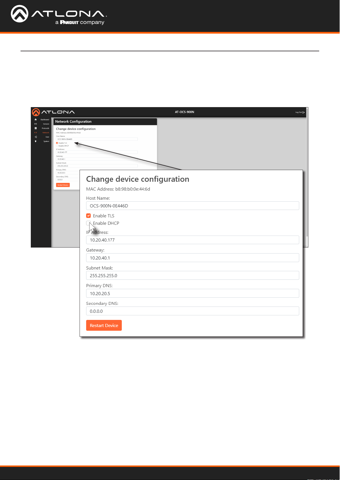
Network Page
The Network page provides controls to adjust network settings.
Network Conguration
Host Name
Enter the desired host name in this eld. Refer to Changing the Hostname (page 17) for more information.
Enable TLS
Click this checkbox to enable or disable Transport Layer Security (TLS). This feature is enabled by default. When
enabled, the checkbox will be checked.
Enable DHCP
Click this checkbox to enable or disable DHCP. This feature is enabled by default. When enabled, the checkbox will
be checked.
AT-OCS-900N
46

Conguration and Management Interfaces
IP Address
Enter the desired IP address for the AT-OCS-900N in this eld. This eld can only be changed when Enable DHCP
is disabled.
Gateway
Enter the IP address of the default gateway (router) in this eld. This eld can only be changed when Enable DHCP
is disabled.
Subnet Mask
Enter the subnet mask in this eld. This eld can only be changed when Enable DHCP is disabled.
Primary DNS / Secondary DNS
Enter the IP address of the primary and secondary DNS servers in these elds.he DNS Server #1 and DNS Server #2
elds. If DNS is not required, these elds can be set to 0.0.0.0. These elds can only be changed when Enable
DHCP is disabled.
Restart Device
Click this button to commit changes and restart the unit.
AT-OCS-900N
47

Conguration and Management Interfaces
User Page
The User page allows the username and password to be changed. Refer to Resetting Login Credentials (page 18)
for more information.
Reset Credentials
Username
Enter the desired user name in this eld.
New Password
Enter the desired password in this eld.
Conrm New Password
Conrm the password by entering it in this eld.
Save
Click this button to commit changes.
AT-OCS-900N
48

Conguration and Management Interfaces
System Page
The System page provides management of various system settings.
System Settings
Name
Enter the name of the device in this eld. Refer to Setting Device Information (page 19) for more information.
Location
Enter the location of the AT-OCS-900N in this eld.
Save
Click this button to commit changes.
Upgrade Firmware
Choose File
Click this button to select the rmware le. Refer to Updating the Firmware (page 51) for more information.
Upload
Click this upload the rmware to the AT-OCS-900N and begin the rmware upgrade process.
AT-OCS-900N
49

Conguration and Management Interfaces
Congure Settings
Download
Click this button to download the current settings to a .json le.
Choose File
Click this button to select the .json settings le.
Upload
Click this button to upload the desired .json settings le to the AT-OCS-900N.
Sensor Actions
Identify Device
Click this button to identify the AT-OCS-900N within the room. During the identication procedure, the LED
indicators within the unit will ash for 30 seconds.
Restart Device
Click this button to restart the unit. Settings are preserved during a restart.
Factory Reset
Click this button to restore the unit to factory-default settings.
AT-OCS-900N
50

Appendix
Updating the Firmware
Using the Web Server
Requirements:
• AT-OCS-900N
• Firmware le
• Computer on the same network as the AT-OCS-900N
1. Download the rmware le from atlona.com and extract the contents of the .zip le to a folder on the computer
desktop.
2. Login to the web server. Refer to Logging in to the Web Server (page 12).
3. Click System in the menu bar.
4. Locate the Upgrade Firmware window group and click the Choose File button.
5. The Open dialog will be displayed. Select the rmware (.bin) le and click the Open button.
6. Click the name of the rmware le will be displayed next to the Choose File button.
Firmware filename
AT-OCS-900N
51

7. Click the Upload button.
8. Another screen will be displayed, showing the progress of the update procedure.
Appendix
IMPORTANT: Make sure to leave this page open during the upload procedure. Do not close this
window while the rmware is being updated.
9. Once the upload process is complete, the AT-OCS-900N will automatically reboot.
10. When the Login page is displayed, the rmware update process is complete.
AT-OCS-900N
52

Appendix
Integration with Velocity
IMPORTANT: Velocity version 2.4.5 or higher required for integration.
Driver Conguration
1. Open the desired web browser and enter the IP address of Velocity.
2. Access the Congure Equipment window for the AT-OCS-900N. Refer to the Velocity User Manual if necessary.
3. The following screen will be displayed.
AT-OCS-900N
53

Appendix
4. Under the AT-OCS-900N Properties window group, modify any settings as desired, then click the SAVE button.
5. Locate the OCS Setup window group.
6. Click the desired checkboxes to customize the settings:
• If the Turn room on when motion is triggered box is checked, then the room will be turned on when
occupied. When this feature is enabled, a checkmark will appear in the box.
• If the Turn room o when there is no motion box is checked, then the room will be turned o when vacant.
When this feature is enabled, a checkmark will appear in the box.
7. In the Total minutes of no activity before shutting room o eld, enter the time interval (in minutes). This is
inclusive of the motion o event timer within the AT-OCS-900N
AT-OCS-900N
54

Appendix
Device Variables
Device variables are used when creating macros which allow for scripted automation of events. Refer to the Velocity
User Manual for more information on creating and using macros.
1. Under the Variables page, click the DEVICE VARIABLES tab.
2. The following screen will be displayed.
The AT-OCS-900N sensors will report their current values and display them in this window, as shown in the
illustration above. The variable names (under the Name column) can be used to display, for example, the current
temperature on a touch panel, or to conditionally trigger an event. Note that these variables values cannot be
modied through Velocity.
AT-OCS-900N
55

Appendix
Integration with AT-OME-MS52W / AT-UHD-SW-510W
The following provides instructions on adding the AT-OCS-900N occupancy sensor as a device. The AutoSwitch
feature on the AT-OME-MS52W / AT-UHD-SW-510W does not need to be enabled for this to work.
IMPORTANT: A username and password must be congured on the AT-OCS-900N before using the
device with the AT-OME-MS52W / AT-UHD-SW-510W.
1. Connect the AT-OCS-900N to the network. Refer to the AT-OCS-900N User Manual for more information.
2. Login to the web server of the AT-OME-MS52W / AT-UHD-SW-510W.
3. Click Display in the side menu bar. The AT-OME-MS52W interface is shown as an example.
4. Click the Display Control Method drop-down list and select Occupancy Sensor.
5. The Occupancy Sensor Control window group will be displayed, as shown:
AT-OCS-900N
56

Appendix
6. Click the Turn Display On on Occupancy checkbox to enable or disable this feature. When enabled, a
checkmark will appear in the checkbox and the occupancy sensor will power-on the display when the room is
occupied.
7. Click the Turn Display O on Vacancy checkbox to enable or disable this feature. When enabled, a checkmark
will appear in the checkbox and the occupancy sensor will power-o the display when the room is no longer
occupied.
8. Enter the IP address of the occupancy sensor in the IP eld.
9. Enter the port number in the Port eld. The default port setting is 9000.
IMPORTANT: When adding an occupancy sensor, it is recommended that a static IP address is
assigned to the occupancy sensor. DHCP is not recommended.
10. Click the Connect button to connect to the occupancy sensor. All connected occupancy sensors will appear
under the Sensors section, as shown below.
11. Click the Identify button to identify the occupancy sensor. This feature is useful when multiple sensors are
connected. See Example A below.
NOTE: Both the AT-OME-MS52W and AT-UHD-SW-510W support a maximum of three AT-OCS-
900N devices.
12. Click the Remove button to delete a sensor from the Sensors list.
13. Setup is complete.
Example A - Multiple occupancy sensors added to the AT-OME-MS52W / AT-UHD-SW-510W.
AT-OCS-900N
57

Appendix
Integration with AT-OME-MS42
NOTE: The AT-OME-MS42 supports a maximum of three AT-OCS-900N devices.
The following provides instructions on adding the AT-OCS-900N occupancy sensor as a device. The AutoSwitch
feature on the AT-OME-MS42 does not need to be enabled for this to work.
IMPORTANT: A username and password must be congured on the AT-OCS-900N before using the
device with the AT-OME-MS42.
1. Connect the AT-OCS-900N to the same network as the AT-OME-MS42. Refer to the AT-OCS-900N User Manual
for more information.
2. Login to the web server of the AT-OME-MS42.
3. Click Display in the top menu bar.
4. Under the Occupancy Sensor Control section, enter the IP address of the AT-OCS-900N in the IP Address
eld.
5. Click the Add button. If the correct IP address was entered and the AT-OCS-900N is found, additional
information will be displayed under the Occupancy Sensor Control section, as shown on the next page.
AT-OCS-900N
58

Appendix
6. Click the Turn Display On on Occupancy toggle to enable or disable this feature. When enabled, the toggle
switch will display as ENABLED and the occupancy sensor will power-on the display when the room is
occupied.
7. Click the Turn Display O on Vacancy toggle to enable or disable this feature. When enabled, the toggle will
display as ENABLED and the occupancy sensor will power-o the display when the room is no longer occupied.
8. Click the Identify button to identify the occupancy sensor. This feature is useful when multiple sensors are
connected.
IMPORTANT: When adding an occupancy sensor, it is recommended that a static IP address is
assigned to the occupancy sensor. DHCP is not recommended.
9. Click the Remove button to delete a sensor from the Sensors list.
10. Setup is complete.
AT-OCS-900N
59

Specications
Motion Sensor
Detection PIR (Passive Infrared)
Coverage Area 900 ft2 (83.6 m2), 2000 ft2 (185.8 m2) with accessory lens
Coverage Pattern 360°
Ambient Light Sensor
Range 0 to 65535 lux
Color Spectrum RGBW, 16-bit
Temperature Sensor Fahrenheit Celsius
Range -40 to +257 -40 to +125
Measurement System Celsius, Fahrenheit, ADC
Ethernet
Port 1 x RJ45
Standards and Protocols MQTT, JSON over WebSocket, mDNS, HTTP/TLS, TCP, UDP
Speeds 10/100 Mbps
Addressing DHCP, Static
Appendix
LED Indicators
Motion Detection 4 - LED, congurable (inner/outer illumination)
Connectors
LAN 1 - RJ45, female
Environmental Fahrenheit Celsius
Operating +32 to +122 0 to +50
Storage -40 to +158 -40 to +70
Humidity (RH) 90% (maximum), non-condensing
Power
Consumption 1.1 W
PoE 802.3af
Dimensions (H x DIA) Inches Millimeters
Unit 2.13 x 2.90 54 x 74
Weight Ounces Grams
Device 2.11 60
Certication
Device CE, FCC, UL 916 le no. #E524557, UKCA
Compliance
NDAA-899 Yes
Warranty
Device 3-year limited
AT-OCS-900N
60

atlona.com • 408.962.0515 • 41.43.508.4321
US International
35280-R13
 Loading...