

Page 1
4K HDR Four-Input HDMI Switcher
with Auto-Switching and Return
Optical Audio
AT-JUNO-451 Installation Guide
Please check http://www.atlona.com/product/AT-JUNO-451
for the most recent firmware update or manual.
The Atlona JunoX™ 451 (AT-JUNO-451) is a 4x1 HDMI switcher for high dynamic range (HDR)
formats. It is HDCP 2.2 compliant and supports 4K/UHD video @ 60 Hz with 4:4:4 chroma
sampling, as well as HDMI data rates up to 18 Gbps. The JunoX 451 is ideal for residential
applications with the latest as well as emerging 4K/UHD and HDR sources and displays. It is
compatible with all video resolutions, audio formats, and color space formats supported in the
HDMI 2.0a specification, plus the ability to pass metadata for HDR content. The JunoX 451 includes
EDID management features and automatic input switching. It also supports the HDMI Audio Return
Channel for receiving digital audio from a television, and includes a TOSLINK digital audio output
for sending this audio to an AV receiver or soundbar. This JunoX Series HDMI switcher can be
controlled via Ethernet, RS-232, and IR. A handheld IR remote control is included.
Package Content
• 1 x Unit
• 1 x Female captive screw connector
5 pin: RS-232 and IR IN
• 2 x Mounting plates
• 4 x Rubber feet
• 4 x Screws
• 1 x IR remote control
• 1 x Installation guide
atlona.com
Toll free: 1-877-536-3976
Local: 1-408-962-0515
Page 2

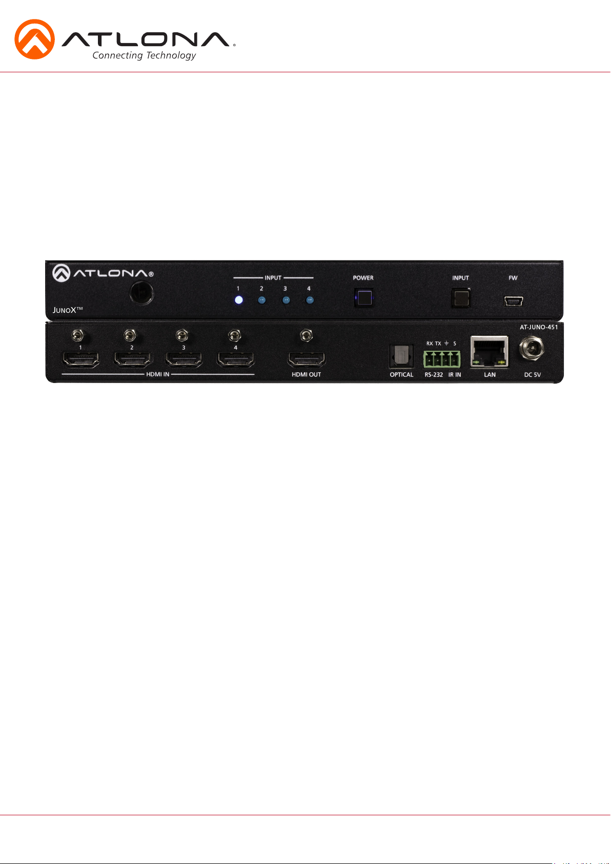
Panel Descriptions
INPUT POWER INPUT FW
1 2 3 4
JUNOX
TM
Front Panel
TM
JUNOX
1
INPUT POWER INPUT FW
1 2 3 4
RX TX S
HDMI IN HDMI OUT OPTICAL RS-232 IR IN LAN DC 5V
321 4
5 76 8 9
3 42
AT-JUNO-451
10
1. INPUT LEDs - LED will illuminate to display the currently selected input
2. POWER button - Turns switcher on or places the unit in standby mode
3. INPUT button - Use to switch between inputs
4. FW port: Firmware update port, connect a mini USB to USB A cable to a computer
Firmware is downloadable through http://www.atlona.com/product/AT-JUNO-451/
5. HDMI IN - Connect HDMI sources to these ports
6. HDMI OUT - Connect HDMI display to this port
7. OPTICAL port - Connect audio cable here for output to an AVR
8. RS-232 / IR IN - Connect to 3rd party control system for control
9. LAN port - Connect network switch or router here for Ethernet, TCP/IP, or webGUI control
10. DC 5V port - Connect included 5V power supply
Remote Control
1. Power On/Off: Turn switcher power on and off
2. Input selection: Selects source
Note: On/off video, audio, and setup buttons are not functional for the
JUNO-451 switcher
Audio Return Channel (ARC)
ARC enables a source connected to a display to route audio back to the
switcher and send the de-embedded audio out the S/PDIF output.
Steps
1. Check to be sure the display supports ARC
2. Enable ARC on the HDMI output of the switcher through RS-232
(command ARC on), TCP/IP, or webGUI
3. Connect the HDMI output port of the switcher to the ARC labeled
input port on the display
Note: The switcher must be connected to the display’s HDMI ARC input
Note: Works well with audio from ARC enabled “Smart” televisions
4. Connect the source to a non ARC HDMI input port on the display
5. Connect the S/PDIF port to an AVR or Zone Amp
SW-R1
On
Video 2
Video
All On
Off
Audio
Vol +
Vol
Mute
-
Power
On
1
2
Off
Video 1
On
Off
Input
1
324
5
S/PDIF audio loop-out
atlona.com
HDMI
HDMI
Audio loop-out
Game Console
AT-JUNO-451
321 4
HDMI IN HDMI OUT OPTICAL RS-232 IR IN LAN DC 5V
Bidirectional HDMI ARC signal
RX TX S
Toll free: 1-877-536-3976
2
Local: 1-408-962-0515
Page 3
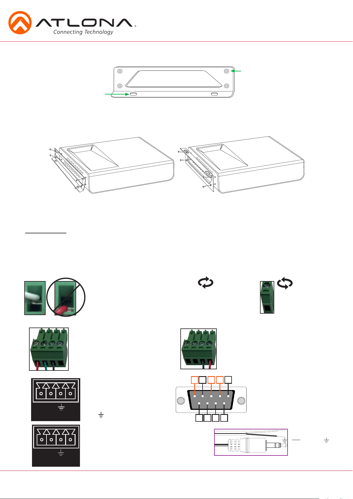
Mounting
IR IN
RS-232
The JunoX comes with mounting brackets that can be used to affix the unit to a table, desk, etc.
Larger oval
hole will be
attached to
the wall/table.
Mounting bracket x 2
Circular holes
will always be
attached to the
unit.
To affix the mounting brackets to the unit, use the four included screws. The bracket can be
affixed with the oval holes pointing to the bottom (for against the wall - picture A) or the oval holes
facing the top (for under tables - picture B).
A
B
Captive Screw
The captive screw connectors allow you to cut cables to a suitable length, reducing cable clutter
while providing a more reliable connection.
Connecting
When connecting the cables to the female captive screw connector it is important that the wires be
terminated correctly. The female captive screw connector has a contact plate at the top and must
have the wires touching it for signal to pass. When wired correctly (see picture A) the signal will pass,
incorrectly (see picture B) no signal will pass.
A
B
The captive screw connectors have
a contact bar that is adjusted to
compress the wire against the top
contact plate. Use the screws at the
top of the connector to compress
Clockwise
Turn the screws clockwise to
raise the contact bar to the
upper contact plate and hold
the wires in place.
Turn the screws counter
clockwise to lower the
contact bar to release the
wires.
Counter
Clockwise
the wire against the contact plate.
1
A female captive screw connector
2
is included: RS-232/IR (see picture 1
& 2).
Pin out color will differ per RS-232
RS-232
RX
TX
cable.
RS-232 pin out will be
determined by the RS-232
cable and will connect as
Rx (receiver), Tx (transmitter),
and (ground). (See picture 2)
4 3 2
5
9
1
Typical pin out:
2 - TX - Transmitter
3 - RX - Receiver
5 - GND - Ground
6
8
7
atlona.com
The IR IN is connected by a ground and
a signal cable. The recommended use of
this port is with a 3rd part control system.
S
Atlona recommends using a AT-LC-CS-IR2M (sold separately) for easy connection.
3
S
Signal (S)
Ground ( )
Toll free: 1-877-536-3976
Local: 1-408-962-0515
Page 4

Ethernet
INPUT POWER INPUT FW
1 2 3 4
JUNOX
TM
For convenience, the JunoX comes with DHCP on. This enables the switcher to be
connected to a network without knowing available IP addresses. If your network does not allow
dynamic IP addresses or if you are using the switcher with a TCP/IP control system, this feature may
be turned off and the IP address set using front panel.
Note: Press and hold the input button on the front panel to switch between static and DHCP IP address.
Two button flashes means the unit is in static mode and four button flashes means the unit is DHCP.
Static IP configuration will be: 192.168.1.254 - 255.255.255.0
Connection Diagram
3
R
M
e
d
i
a
3
Video
Audio
Video
Game Console
Video
Video
RX TX S
321 4
HDMI IN HDMI OUT OPTICAL RS-232 IR IN LAN DC 5V
Video
Video
Audio
AT-JUNO-451
Audio
Troubleshooting
1. How do I update my unit?
Firmware and instructions can be found and downloaded from the firmware tab at
http://www.atlona.com/product/AT-JUNO-451
2. What types of control can be used with my unit?
The Juno can be controlled using TCP/IP, RS-232, webGUI, or AMS
3. Why is my unit not auto switching?
Auto switching comes disabled. Auto switching can be enabled through AMS, webGUI, or
RS-232 - TCP/IP using the ‘AutoSW on’ command.
Note: All RS-232 and TCP/IP commands are followed by a carriage return
atlona.com
Toll free: 1-877-536-3976
4
Local: 1-408-962-0515
 Loading...