


Stereo / Mono
Audio Power Amplier
60 Watts
AT-GAIN-60
Atlona Manuals
Audio

Version Information
Version Release Date Notes
1 04/18 Initial release
2 11/18 Firmware version 1.0.03; added auto power-on feature
AT-GAIN-60
2

Welcome to Atlona!
Thank you for purchasing this Atlona product. We hope you enjoy it and will take an extra few moments to register
your new purchase.
Registration only takes a few minutes and protects this product against theft or loss. In addition, you will receive
notications of product updates and rmware. Atlona product registration is voluntary and failure to register will not
aect the product warranty.
To register your product, go to http://www.atlona.com/registration
Sales, Marketing, and Customer Support
Main Oce
Atlona Incorporated
70 Daggett Drive
San Jose, CA 95134
United States
Oce: +1.877.536.3976 (US Toll-free)
Oce: +1.408.962.0515 (US/International)
Sales and Customer Service Hours
Monday - Friday: 6:00 a.m. - 4:30 p.m. (PST)
http://www.atlona.com/
Operating Notes
IMPORTANT: Visit http://www.atlona.com/product/AT-GAIN-60 for the latest rmware updates and
User Manual.
International Headquarters
Atlona International AG
Ringstrasse 15a
8600 Dübendorf
Switzerland
Oce: +41 43 508 4321
Sales and Customer Service Hours
Monday - Friday: 09:00 - 17:00 (UTC +1)
©2018 Atlona, Inc. All Rights Reserved. All trademarks are the property of their respective owners.
Atlona reserves the right to make changes to the hardware, packaging, and documentation without notice.
AT-GAIN-60
3

Atlona, Inc. (“Atlona”) Limited Product Warranty
Coverage
Atlona warrants its products will substantially perform to their published specications and will be free from defects
in materials and workmanship under normal use, conditions and service.
Under its Limited Product Warranty, Atlona, at its sole discretion, will either:
• repair or facilitate the repair of defective products within a reasonable period of time, restore products to their
proper operating condition and return defective products free of any charge for necessary parts, labor and
shipping.
OR
• replace and return, free of charge, any defective products with direct replacement or with similar products
deemed by Atlona to perform substantially the same function as the original products.
OR
• refund the pro-rated value based on the remaining term of the warranty period, not to exceed MSRP, in cases
where products are beyond repair and/or no direct or substantially similar replacement products exist.
Repair, replacement or refund of Atlona products is the purchaser’s exclusive remedy and Atlona liability does not
extend to any other damages, incidental, consequential or otherwise.
This Limited Product Warranty extends to the original end-user purchaser of Atlona products and is non-transferrable
to any subsequent purchaser(s) or owner(s) of these products.
Coverage Periods
Atlona Limited Product Warranty Period begins on the date of purchase by the end-purchaser. The date contained on
the end-purchaser ‘s sales or delivery receipt is the proof purchase date.
Limited Product Warranty Terms – New Products
• 10 years from proof of purchase date for hardware/electronics products purchased on or after June 1, 2013.
• 3 years from proof of purchase date for hardware/electronics products purchased before June 1, 2013.
• Lifetime Limited Product Warranty for all cable products.
Limited Product Warranty Terms – Refurbished (B-Stock) Products
• 3 years from proof of purchase date for all Refurbished (B-Stock) hardware and electronic products purchased
on or after June 1, 2013.
Remedy
Atlona recommends that end-purchasers contact their authorized Atlona dealer or reseller from whom they
purchased their products. Atlona can also be contacted directly. Visit www.atlona.com for Atlona’s contact
information and hours of operation. Atlona requires that a dated sales or delivery receipt from an authorized dealer,
reseller or end-purchaser is provided before Atlona extends its warranty services. Additionally, a return merchandise
authorization (RMA) and/or case number, is required to be obtained from Atlona in advance of returns.
Atlona requires that products returned are properly packed, preferably in the original carton, for shipping. Cartons not
bearing a return authorization or case number will be refused. Atlona, at its sole discretion, reserves the right to reject
any products received without advanced authorization. Authorizations can be requested by calling 1-877-536-3976
(US toll free) or 1-408- 962-0515 (US/international) or via Atlona’s website at www.atlona.com.
Exclusions
This Limited Product Warranty excludes:
• Damage, deterioration or malfunction caused by any alteration, modication, improper use, neglect, improper
packaging or shipping (such claims must be presented to the carrier), lightning, power surges, or other acts of
nature.
AT-GAIN-60
4

Atlona, Inc. (“Atlona”) Limited Product Warranty
• Damage, deterioration or malfunction resulting from the installation or removal of this product from any
installation, any unauthorized tampering with this product, any repairs attempted by anyone unauthorized by
Atlona to make such repairs, or any other cause which does not relate directly to a defect in materials and/or
workmanship of this product.
• Equipment enclosures, cables, power supplies, batteries, LCD displays, and any accessories used in conjunction
with the product(s).
• Products purchased from unauthorized distributors, dealers, resellers, auction websites and similar unauthorized
channels of distribution.
Disclaimers
This Limited Product Warranty does not imply that the electronic components contained within Atlona’s products
will not become obsolete nor does it imply Atlona products or their electronic components will remain compatible
with any other current product, technology or any future products or technologies in which Atlona’s products may
be used in conjunction with. Atlona, at its sole discretion, reserves the right not to extend its warranty oering in
instances arising outside its normal course of business including, but not limited to, damage inicted to its products
from acts of god.
Limitation on Liability
The maximum liability of Atlona under this limited product warranty shall not exceed the original Atlona MSRP for
its products. To the maximum extent permitted by law, Atlona is not responsible for the direct, special, incidental or
consequential damages resulting from any breach of warranty or condition, or under any other legal theory. Some
countries, districts or states do not allow the exclusion or limitation of relief, special, incidental, consequential or
indirect damages, or the limitation of liability to specied amounts, so the above limitations or exclusions may not
apply to you.
Exclusive Remedy
To the maximum extent permitted by law, this limited product warranty and the remedies set forth above are
exclusive and in lieu of all other warranties, remedies and conditions, whether oral or written, express or implied.
To the maximum extent permitted by law, Atlona specically disclaims all implied warranties, including, without
limitation, warranties of merchantability and tness for a particular purpose. If Atlona cannot lawfully disclaim
or exclude implied warranties under applicable law, then all implied warranties covering its products including
warranties of merchantability and tness for a particular purpose, shall provide to its products under applicable law.
If any product to which this limited warranty applies is a “Consumer Product” under the Magnuson-Moss Warranty
Act (15 U.S.C.A. §2301, ET SEQ.) or other applicable law, the foregoing disclaimer of implied warranties shall not
apply, and all implied warranties on its products, including warranties of merchantability and tness for the particular
purpose, shall apply as provided under applicable law.
Other Conditions
Atlona’s Limited Product Warranty oering gives legal rights, and other rights may apply and vary from country to
country or state to state. This limited warranty is void if (i) the label bearing the serial number of products have been
removed or defaced, (ii) products are not purchased from an authorized Atlona dealer or reseller. A comprehensive
list of Atlona’s authorized distributors, dealers and resellers can be found at www.atlona.com.
AT-GAIN-60
5

Important Safety Information
The lightning ash with arrowhead symbol, within an equilateral triangle, is intended to alert the user to the presence
of uninsulated “dangerous voltage” within the product’s enclosure that may be of sucient magnitude to constitute a
risk of electric shock to persons.
Das Symbol des Blitzzeichens innerhalb eines gleichseitigen Dreiecks soll den Benutzer davor warnen, dass
innerhalb des Gehäuses gefährlich hohe Spannung an berührbaren Teilen anliegt. Die Spannung ist hoch genug um
bei Berührung zu einem gefährlichen elektrischen Schlag zu führen!
三角形內帶有箭頭符號的閃電,旨意在提醒用戶產品外殼內存在未絕緣的“危險電壓”可能會造成人體觸電危險
Вспышка молнии с символом стрелки в треугольнике предназначена для предупреждения пользователя о
наличии неизолированного «опасного напряжения» в корпусе продукта, которое может иметь достаточную
величину, чтобы представлять опасность поражения электрическим током для людей
Le ash lumineux dans le symbole de la èche du triangle équilatéral est destiné à alerter l’utilisateur de la présence
d’une «tension dangereuse» non isolée dans l’enceinte du produit qui peut être susamment importante pour
constituer un risque d’électrocution pour les personnes
Il simbolo del lampo con la punta di una freccia, all’interno di un triangolo equilatero, avvisa l’utente della presenza di
“tensioni pericolose” non isolate all’interno del contenitore del prodotto che possono essere sucientemente elevate
da costituire un rischio di folgorazione per le persone.
El símbolo del rayo con punta de echa dentro de un triángulo equilátero alerta al usuario de la presencia de “voltaje
peligroso” no aislado en el interior del producto que puede ser de una magnitud suciente como para constituir un
riesgo de descarga eléctrica para las personas.
AT-GAIN-60
6

Important Safety Information
CAUTION
RISK OF ELECTRIC SHOCK
DO NOT OPEN
CAUTION: TO REDUCT THE RISK OF
DO NOT OPEN ENCLOSURE OR EXPOSE
The exclamation point within an equilateral triangle is intended to alert the user to
the presence of important operating and maintenance instructions in the literature
accompanying the product.
The information bubble is intended to alert the user to helpful or optional operational instructions in the literature accompanying the product.
ELECTRIC SHOCK
TO RAIN OR MOISTURE.
NO USER-SERVICEABLE PARTS
INSIDE REFER SERVICING TO
QUALIFIED SERVICE PERSONNEL.
1. Read these instructions.
2. Keep these instructions.
3. Heed all warnings.
4. Follow all instructions.
5. Do not use this product near water.
6. Clean only with a dry cloth.
7. Do not block any ventilation openings. Install in
accordance with the manufacturer’s instructions.
8. Do not install or place this product near any heat
sources such as radiators, heat registers, stoves, or
other apparatus (including ampliers) that produce
heat.
9. Do not defeat the safety purpose of a polarized
or grounding-type plug. A polarized plug has two
blades with one wider than the other. A grounding
type plug has two blades and a third grounding
prong. The wide blade or the third prong are
provided for your safety. If the provided plug does
not t into your outlet, consult an electrician for
replacement of the obsolete outlet.
10. Protect the power cord from being walked on
or pinched particularly at plugs, convenience
receptacles, and the point where they exit from the
product.
11. Only use attachments/accessories specied by
Atlona.
12. To reduce the risk of electric shock and/or damage
to this product, never handle or touch this unit or
power cord if your hands are wet or damp. Do not
expose this product to rain or moisture.
13. Unplug this product during lightning storms or when
unused for long periods of time.
14. Refer all servicing to qualied service personnel.
Servicing is required when the product has been
damaged in any way, such as power-supply cord or
plug is damaged, liquid has been spilled or objects
have fallen into the product, the product has been
exposed to rain or moisture, does not operate
normally, or has been dropped.
FCC Statement
FCC Compliance and Advisory Statement: This hardware device complies with
Part 15 of the FCC rules. Operation is subject to the following two conditions: 1)
this device may not cause harmful interference, and 2) this device must accept any
interference received including interference that may cause undesired operation. This
equipment has been tested and found to comply with the limits for a Class A digital
device, pursuant to Part 15 of the FCC Rules. These limits are designed to provide
reasonable protection against harmful interference in a commercial installation.
This equipment generates, uses, and can radiate radio frequency energy and, if not
installed or used in accordance with the instructions, may cause harmful interference
to radio communications. However there is no guarantee that interference will not occur in a particular installation. If
this equipment does cause harmful interference to radio or television reception, which can be determined by turning
the equipment o and on, the user is encouraged to try to correct the interference by one or more of the following
measures: 1) reorient or relocate the receiving antenna; 2) increase the separation between the equipment and the
receiver; 3) connect the equipment to an outlet on a circuit dierent from that to which the receiver is connected;
4) consult the dealer or an experienced radio/TV technician for help. Any changes or modications not expressly
approved by the party responsible for compliance could void the user’s authority to operate the equipment. Where
shielded interface cables have been provided with the product or specied additional components or accessories
elsewhere dened to be used with the installation of the product, they must be used in order to ensure compliance
with FCC regulations.
AT-GAIN-60
7

Table of Contents
Introduction 9
Features 9
Package Contents 9
Panel Description 10
Installation 11
Audio Connectors 11
AUDIO IN 11
4 / 8 Ω OUT 11
24 / 70 / 100V 11
RS-232 12
Connection Instructions 13
Connection Diagrams 14
IP Conguration 15
Using the Rear Panel 15
Using Commands 16
Using the Web GUI 17
Basic Operation 19
LED Indicators 19
Locking the Front Panel 20
Power Modes 21
Powering On or O 21
Auto Power On mode 22
Auto Power Down mode 22
Factory Reset 23
The Web GUI 24
Introduction to the Web GUI 24
Menu Bar 25
Status page 26
Firmware page 27
Network page 28
Control page 30
Users page 32
Audio page 33
Appendix 34
Updating the Firmware 34
Rack Mount Installation 36
Default Settings 39
Specications 40
Index 42
AT-GAIN-60
8

Introduction
The Atlona Gain™ 60 (AT-GAIN-60) is a compact power amplier designed for low or high-impedance applications.
A mode selector switch allows the Gain 60 to deliver two channels of 30 watts each into 4 or 8 ohms, or a single
channel of 60 watts at 24, 70, or 100 volts. This Class-D amplier is energy ecient and ENERGY STAR qualied,
and is also convection-cooled without the need for fans. Additionally, the Gain 60 is UL 2043 plenum rated,
allowing convenient yet discreet installation in a plenum airspace above a drop ceiling. Balanced and unbalanced
audio inputs are provided for system design versatility. The Gain 60 is controllable via TCP/IP or RS-232, and can
be integrated with Atlona AV switchers and OmniStream™ AV systems for a wide variety of sound reinforcement
applications.
Features
• Selectable low or high-impedance operation.
» 2 x 30 watts @ 4 or 8 ohms.
» 1 x 60 watts @ 24, 70 or 100 volts.
• Selectable balanced and unbalanced audio inputs.
• Class-D ecient amplier design.
• ENERGY STAR® qualied.
• Convection cooled – no need for fans.
• UL 2043 plenum-rated – allows installation above commercial drop ceilings.
• Automatic standby, congurable from 5 to 25 minutes of inactivity, to minimize power consumption.
• Rear panel input level control.
• Integrated protection circuitry automatically activates in the event of clipping, short circuit, thermal overload, and
more.
• Bass and treble tone controls.
• TCP/IP and RS-232 control of volume level, muting, and tone controls.
• Ideal for IP-based control from Atlona Velocity™ Control System.
• Front-panel button controls for input selection, mute, and volume control.
• Front panel signal status LEDs for power, input selection, mute, and real-time volume level.
• Compact, rack-mountable enclosure.
• Optional AT-RACK-1RU rack shelf – recommended for rack installation.
• Includes installation guide, captive screw connectors, and external universal power supply.
Package Contents
1 x AT-GAIN-60
2 x Captive screw connector, 2-pin
1 x Captive screw connector, 4-pin
2 x Captive screw connector, 5-pin
1 x 28 V / 3.4 A DC power supply
1 x Installation Guide
AT-GAIN-60
9

Panel Description
2 4 6 7 8 9 11 13 15 161
Front Rear
3 5 10 12 14 17
TX RX
L
R
CLASS 2 WIRING
24 / 70 / 100V OUT
-9
-4
-14
-19
-20
-22
dB
INPUT GAIN
-2
L R
CLASS 2 WIRING
DC28VAUDIO IN 2
3.4A
1 PWR
This LED indicator glows solid green when the unit
is powered. When set to standby mode, this LED
indicator glows solid amber.
2 1 / 2
These LED indicators display the currently selected
input. The active input will be indicated by a solid
green LED.
3 INPUT
Press this button to select the desired audio input.
4 Mute LED Indicator
This LED indicator will glow solid red when the audio
output is muted.
5 MUTE
Press this button to mute the audio output. Press the
button again to unmute the audio output.
6 VOL
Press the up-arrow button to increase the output
volume. Press the down-arrow button to decrease
the output volume. The LEDs on the Audio Output
Indicator will change each time one of these buttons
is pressed.
10 AUDIO IN 2 (unbalanced)
Connect RCA cables, from an analog line output,
to these ports. Both analog stereo or two mono
connections are supported. Input impedance is
10 kΩ.
11 AUDIO IN 1
Connect the included captive screw connector, from
a balanced / unbalanced analog line output, to this
port. Input impedance is 20 kΩ. Refer to Audio
Connectors (page 11) for wiring information.
12 INPUT GAIN
Turn this pot to adjust the audio input gain in 4 dB
increments.
13 24 / 70 / 100V
Connect the included 2-pin captive screw connector
from this port to a distributed speaker system.
Before connecting the speakers, set the speaker
voltage using the OUTPUT MODE switch.
14 4 / 8 Ω OUT
Connect the included 4-pin captive screw connector
from this port to a pair of program / stereo speakers.
Before connecting the speakers, set the speaker
impedance using the OUTPUT MODE switch.
7 Audio Output Indicator
Displays the output audio level. If the volume level
peaks at the red indicator (0 dB), then clipping will
occur.
8 LAN
Connect an Ethernet cable from this port to the Local
Area Network (LAN).
9 RS-232
Connect the included 3-pin captive screw connector
from this port to an RS-232 controller or automation
system. Refer to RS-232 (page 12) for wiring
information.
AT-GAIN-60
15 OUTPUT MODE
Slide this switch to set the correct speaker
impedance or voltage setting before connecting the
speakers.
16 RESET
Press and hold this button for 10 seconds to reset
the unit to factory-default settings. Refer to Factory
Reset (page 23) for more information.
17 DC 28V
Connect the included 28V DC power supply to this
power receptacle.
10
Installation
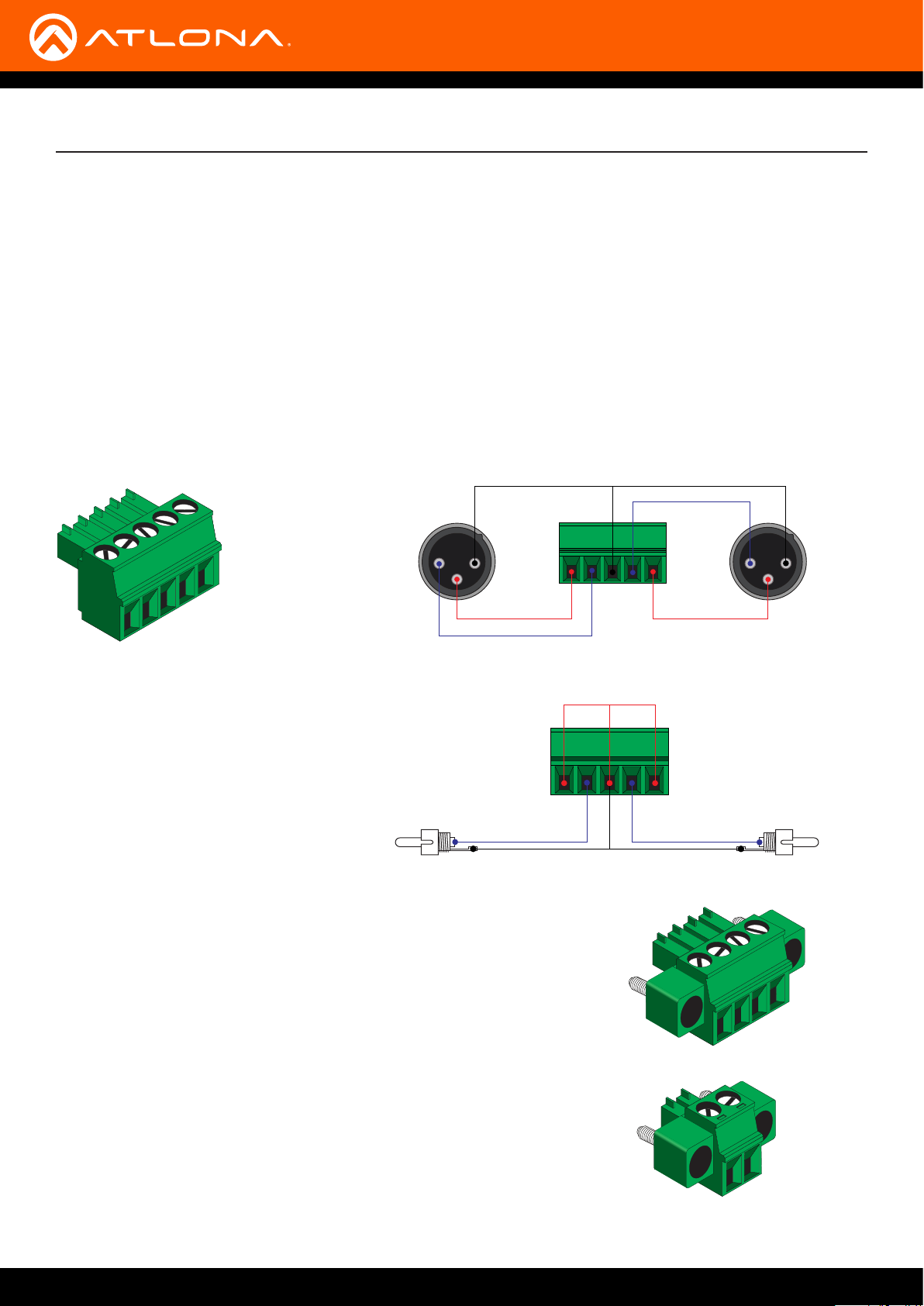
Audio Connectors
The AT-GAIN-60 provides two audio ports: one input and one output. The AUDIO IN 1 port can be used to connect
an audio digital signal processor (DSP) or other audio source device. Balanced or unbalanced wiring is supported.
The AUDIO IN 2 port is used to connect an analog audio source using RCA-type cables.
1. Use wire strippers to remove a portion of the cable jacket.
2. Remove at least 3/16” (5 mm) from the insulation of each wire.
3. Connect the wires as shown, using either balanced or unbalanced wiring.
AUDIO IN
Balanced audio using XLR connectors
GND GND
+
Rear View
2 1
3
-
-
+
Unbalanced audio using RCA connectors
-
-
+
Side View Side View
GND
+
GND
2 1
3
Rear View
4 / 8 Ω OUT
Connect program/stereo speakers to the included 4-pin captive screw
connector, then connect the terminal block to the 4 / 8 Ω OUT port.
When connecting program / stereo speakers, set the MODE switch to
either 4 Ω or 8 Ω, depending upon the speaker impedance.
24 / 70 / 100V
Connect distributed speaker system to the included 2-pin captive screw
connector, then connect the terminal block to the 24 / 70 / 100V port.
When connecting program / stereo speakers, set the MODE switch to
24, 70, or 100V, depending upon the speaker voltage.
AT-GAIN-60
11

Installation
RS-232
The AT-GAIN-60 provides RS-232 control between an automation system and an RS-232 device. This step is
optional.
1. Use wire strippers to remove a portion of the cable jacket.
2. Remove at least 3/16” (5 mm) from the insulation of the RX, TX, and GND wires.
3. Insert the TX, RX, and GND wires into correct terminal on the included captive screw block.
TX
RX
GND
5 3 2
AT-GAIN-60
12

Installation
Connection Instructions
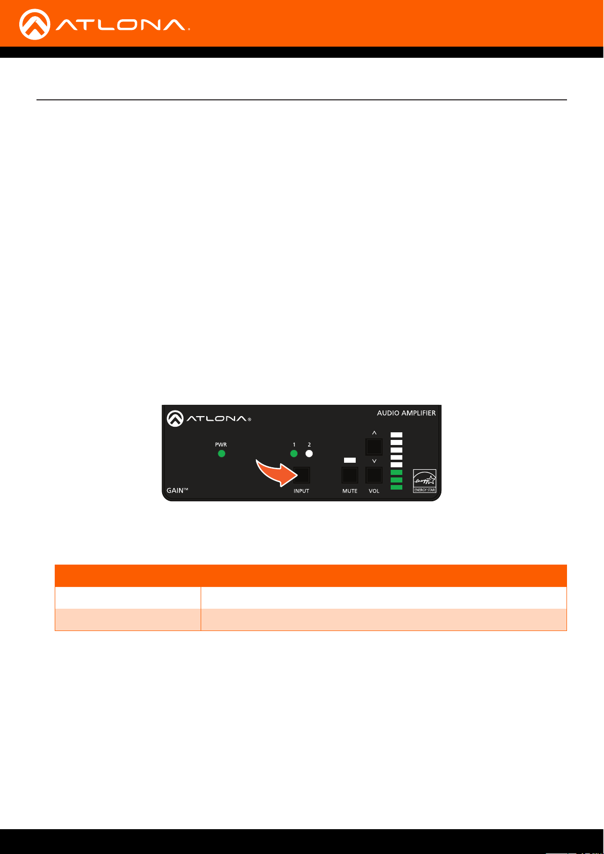
1. Connect an analog audio source to the AUDIO IN ports. Once connected, press the INPUT button on the front
panel, to switch between the RCA and the 5-pin captive screw port.
• RCA cables (unbalanced)
Connect shielded RCA-type cables from the audio source to the AUDIO IN 2 left/right RCA jacks.
• Balanced/Unbalanced
Connect the included 5-pin captive screw to the AUDIO IN 1 port. Use the desired wiring conguration, on
the previous page.
2. Determine the use-case scenario of the AT-GAIN-60. The AT-GAIN-60 can be congured as either one of the
following. Only one type of speaker connection is permitted at a time.
• Distributed speaker system (high impedance)
Set the OUTPUT MODE switch to the required voltage setting: 24, 70, or 100V. This mode is used for
commercial applications and longer speaker cable runs.
• Program speakers / stereo (low impedance)
Set the OUTPUT MODE switch to the impedance setting of the speakers being connected: 4Ω or 8Ω.
This mode is used for consumer applications and shorter speaker cable runs.
Refer to Connection Diagrams (page 14) for example applications.
Distributed speakers (high-Z)
R
TX RX
L
CLASS 2 WIRING
24 / 70 / 100V OUT
-9
-4
-14
-19
-20
-22
dB
INPUT GAIN
-2
L R
CLASS 2 WIRING
DC28VAUDIO IN 2
3.4A
Program / stereo speakers (low-Z)
NOTE: The AT-GAIN-60 only supports one type of speaker connection at a time: high-impedance or
low-impedance.
3. Connect the speakers to the proper port on the AT-GAIN-60, based on the selection made in the previous step.
4. Connect the LAN port to a network switch for set up and control of the unit.
5. Connect the included power supply to the DC28V power receptacle.
6. Connect the IEC power cable to an available electrical outlet.
AT-GAIN-60
13

AT-VTP-550-BL
Program / Stereo Speakers Application
Installation
Connection Diagrams
Program Speakers
Generic
SPEAKER SYSTEMS
Generic
SPEAKER SYSTEMS
2
AT-VGW-250
1
ETHERNET
HDMI OUT
MDP OUT DC 19V
AT-VGW-250
Ethenet
LAN
Ethernet / PoE
AT-VTP-800-WH
Distributed Speakers Application
Audio
Ethernet
Audio
AT-GAIN-60
Ethernet
Audio
Video
Laptop
AT-UHD-SW-510W
AT-UHD-SW-510W
Tablet
(BYOD)
DISPLAYINPUT
USB-C
DP
HDMI 3
HDMI 4
BYOD
Video
UHD/HD Display
Laptop
2
1
ETHERNETHDMI OUTMDP OUT DC 19V
AT-VGW-250
AT-VGW-250
Ethernet
Ethernet / PoE
Ethernet
LAN
Display
AT-GAIN-60
Audio
Generic
SPEAKER SYSTEMSSPEAKER SYSTEMS
HDMI
AT-HDVS-210U-TX-WP
PWR
LINK
USB-C
HDMI
AT-HDVS-210U-TX-WP
Ethernet
Audio
AT-HDVS-SC-RX
USB-CHDMI
RS-232
RXTX
HDBaseT
4K SCALER
LAN
INPUT
>
<
INPUT
1
ENTER
2
PWR
MENU
LINK
AT-HDVS-SC-RX
HDMI
Control
IMPORTANT: When connecting speakers, either use a distributed speaker system or program/
stereo speakers. The AT-GAIN-60 does not support simultaneous distributed and program speaker
connections.
Generic
SPEAKER SYSTEMSSPEAKER SYSTEMS
Generic
SPEAKER SYSTEMSSPEAKER SYSTEMS
Generic
SPEAKER SYSTEMSSPEAKER SYSTEMS
Ceiling Speakers
AT-GAIN-60
14
Installation
IP Conguration
The AT-GAIN-60 is shipped with DHCP enabled. Once connected to a network, the DHCP server (if available), will
automatically assign an IP address to the unit. Execute the arp -a command at the Windows command line or use an
IP scanner to locate the AT-GAIN-60 on the network.
If the AT-GAIN-60 is unable to detect a DHCP server, within 15 seconds, then the unit will be assigned the following
IP conguration:
• IP address 192.168.1.254
• Subnet mask 255.255.0.0
• Gateway 192.168.1.1
If a static IP address is desired, the unit can be switched to static IP mode. Use one of the following procedures to
switch between DHCP and static IP mode. 192.168.1.254 is the default static IP address.
Using the Rear Panel
1. Make sure the AT-GAIN-60 is powered.
2. Press and hold the INPUT button for approximately 10 seconds.
3. Release the IP RESET button once the PWR LED indicator on the front panel begins to ash. The number of
ashes will indicate the currently selected IP mode.
POWER LED ashes Description
Two Static IP mode
Four DHCP mode
4. Once the unit has changed IP modes, the unit will automatically reboot.
5. The unit is now set to the new IP mode and ready for use.
AT-GAIN-60
15

Installation
Using Commands
Use the IPStatic and IPDHCP commands to switch between DHCP and static IP mode using Telnet or RS-232.
Refer to the Application Programmers Interface documentation for more information. All commands and their
arguments are case-sensitive.
• Setting static IP mode
1. Connect to the AT-GAIN-60 using Telnet.
2. At the command line, execute the IPDHCP command using the o argument, as shown.
IPDHCP o
3. Execute the IPStatic command. This command requires three arguments: the desired IP address of the
AT-GAIN-60, the subnet mask, and the gateway address. All arguments must be entered in dot-decimal
notation. The following is an example:
IPStatic 192.168.1.112 255.255.255.0 192.168.1.1
4. The AT-GAIN-60 will automatically reboot. The unit is now set to static IP mode and ready for use.
• Setting DHCP mode
1. Connect to the AT-GAIN-60 using Telnet.
2. At the command line, execute the IPDHCP command using the on argument, as shown. All characters are
case-sensitive.
IPDHCP on
3. The AT-GAIN-60 will automatically reboot. The unit is now set to DHCP mode and will be assigned an IP
address by the DHCP server (if present).
AT-GAIN-60
16

Installation
Using the Web GUI
The Network page (page 28) in the web GUI allows the option for the AT-GAIN-60 to use either DHCP or static IP
mode. In order to access the web GUI, the IP address of the AT-GAIN-60 must be known.
1. Open the desired web browser and enter the IP address of the AT-GAIN-60.
2. Log in, using the required credentials. The factory-default username and password are listed below:
Username: admin
Password: Atlona
3. Click the Network tab, located on the side menu bar.
• Setting static IP mode
a. Click OFF, next to DHCP.
b. Enter the required information in the IP Address, Subnet, and Gateway elds.
• Setting DHCP mode
a. Click ON, next to DHCP.
4. Click the Save button to save the changes.
AT-GAIN-60
17

5. The following message box will be displayed:
6. Click OK to accept the changes or click Cancel to abort changes and return to the Network page.
Installation
AT-GAIN-60
18

Basic Operation
LED Indicators
The LED indicators on the front panel, provide information on the current state of the AT-GAIN-60. Refer to the table
below for more information.
LED Indicator State Description
PWR Solid green
Solid amber
Flashing green
O
Unit is powered.
Unit is in low power consumption mode.
Unit is in blink mode.
Unit is not powered.
1 Solid green
O
2 Solid green
O
MUTE Solid red
O
Audio Output
Indicators
Solid green
Solid amber
Solid red
• Check the power cable between the ATGAIN-60 and the electrical outlet.
• Make sure that the electrical outlet is live.
The AUDIO IN 1 port is the active audio input.
The AUDIO IN 1 port is not the active audio input.
The AUDIO IN 2 ports (RCA) are the active audio
input.
The AUDIO IN 2 ports (RCA) are not the active
audio input.
Audio output is muted.
Audio muting is disabled.
Acceptable range for output volume.
Output volume level is approaching audio clipping.
Audio clipping.
NOTE: All LED indicators on the front panel will ash rapidly when a rmware update is in progress.
Refer to Updating the Firmware (page 34) for more information.
AT-GAIN-60
19

Basic Operation
Locking the Front Panel
The buttons on the front panel can be locked or unlocked. Locking the front-panel buttons prevents accidental
pressing of the buttons, which may occur when the unit is mounted in a rack environment. Locking and unlocking of
the front-panel buttons is managed through the web GUI or by executing the Lock and Unlock API commands. Refer
to the API documentation for more information.
1. Login to the web GUI. Refer to Introduction to the Web GUI (page 24) for more information.
2. Click Control, under the Settings menu, on the left side of the page.
3. Click LOCK to lock the front-panel buttons. To unlock the front-panel buttons, click UNLOCK.
Locking the front panel does not aect access to the web GUI or Telnet sessions.
AT-GAIN-60
20

Basic Operation
Power Modes
The following section discusses the power mode features which have been integrated into the AT-GAIN-60.
Power modes are located under the Control tab within the web GUI.
1. Open the desired web browser and enter the IP address of the AT-GAIN-60.
2. Log in, using the required credentials. The factory-default username and password are listed below:
Username: admin
Password: Atlona
3. Click the Control tab, located on the side menu bar. The Control Settings section will be displayed.
Powering On or O
Click the OFF option to power-o the AT-GAIN-60. When powered-o, audio output is disabled but the LAN port will
remain active. To power-on the AT-GAIN-60, after it has been powered-o, any one of the following methods may be
used:
• Set Power to the ON setting, in the web GUI.
• Execute the PWON command using RS-232 or Telnet.
• Press any of the buttons on the front panel to wake the unit.
AT-GAIN-60
21
Basic Operation
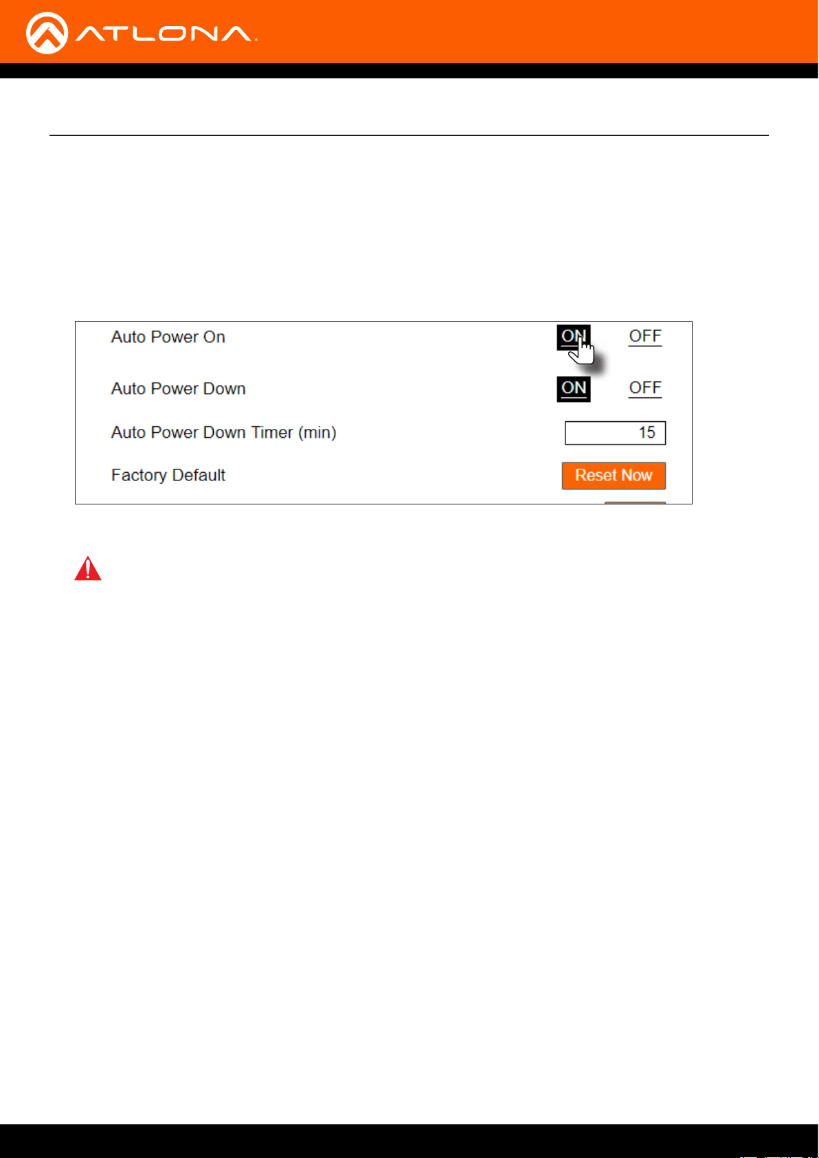
Auto Power On mode
When enabled, Auto Power On mode will automatically power-on the AT-GAIN-60 when an input signal is detected
on either the AUDIO IN 1 or AUDIO IN 2 port. When the AT-GAIN-60 is powered-on from a low-power state, the
PWR, INPUT, and VOL LED indicators will be illuminated. By default this feature is enabled.
1. Click the ON option, if not already selected, to enable Auto Power On mode.
2. Click OFF to disable this feature.
IMPORTANT: When Auto Power On is set to ON and an audio signal is present, the AT-GAIN-60
cannot be powered-o in the web GUI or through a Telnet session. To control powering of the ATGAIN-60, regardless of whether or not an input signal is present, the Auto Power O feature must be
set to OFF.
Auto Power Down mode
Enabling this mode will automatically power-down the AT-GAIN-60 if no audio input signal is present on either the
AUDIO IN 1 port or the AUDIO IN 2 port, after the specied time interval. When the AT-GAIN-60 enters Auto Power
Down mode, the Power option will be set to OFF and the front-panel LED indicators will turn o. In Auto Power
Down mode, power consumption is limited to 1.2 W. By default this feature is enabled.
Note that when this mode is enabled, the AT-GAIN-60 only monitors the existence of an audio input signal, not the
physical audio connection. Refer to the next page for instructions.
1. Click the ENABLE option, if it is not selected.
2. Set the time interval, which must elapse, before the AT-GAIN-60 powers-down. The default setting is 15 minutes.
AT-GAIN-60
22

Basic Operation
Factory Reset
If necessary, the AT-GAIN-60 can be reset to factory-default settings. Note that the AT-GAIN-60 will be placed in
DHCP mode, as part of the reset procedure. The AT-GAIN-60 can also be reset through the web GUI. Refer to the
Control page (page 30) for more information.
1. Press and hold the RESET button on the back panel, using the end of a paper clip or other pointed object, for
approximately 10 seconds.
R
L
TX RX
CLASS 2 WIRING
24 / 70 / 100V OUT
-9
-4
L R
-2
-14
-19
-20
-22
dB
INPUT GAIN
CLASS 2 WIRING
2. Release the RESET button once a “clicking” sound is heard.
3. Factory reset is complete.
DC28VAUDIO IN 2
3.4A
AT-GAIN-60
23

The Web GUI
Introduction to the Web GUI
The AT-GAIN-60 includes a built-in web GUI. Atlona recommends that the web GUI be used to set up the
AT-GAIN-60, as it provides intuitive management of all features.
The AT-GAIN-60 is shipped with DHCP enabled. Once connected to a network, the DHCP server will automatically
assign an IP address to the unit. Use an IP scanner to determine the IP address of the AT-GAIN-60. If a static
IP address is desired, refer to IP Conguration (page 15). The default static IP address of the AT-GAIN-60 is
192.168.1.254.
1. Launch a web browser.
2. In the address bar, type the IP address of the AT-GAIN-60.
3. The Login page will be displayed.
4. Type admin, using lower-case characters, in the Username eld.
5. Type Atlona in the Password eld. This is the default password. The password eld is case-sensitive. When the
password is entered, it will be masked. The password can be changed, if desired. Refer to Users page (page
32) for more information.
6. Click the Login button or press the ENTER key on the keyboard.
AT-GAIN-60
24

The Web GUI
7. The Status page will be displayed.
8. To logout of the web GUI at any time, click Logout on the side menu bar. Once logged out, the AT-GAIN-60 will
display the login screen.
Menu Bar
The window on the left side of the screen is the menu bar. The menu system is divided into three sections:
Home, Settings, and Conguration. When the mouse is moved over each menu item, it will be highlighted in black.
Click the menu item to go that page.
Menu bar
AT-GAIN-60
25
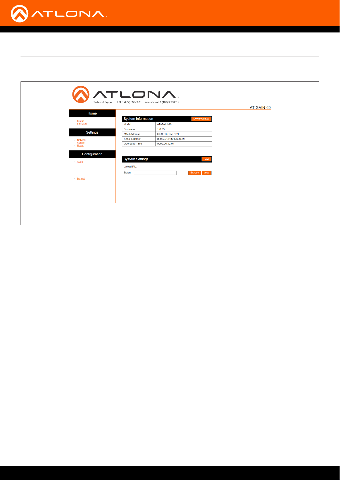
Status page
The Web GUI
Download Log
Click this button to download a log of command events to the computer’s hard disk.
Model
The SKU of this product.
Firmware
The current rmware version installed.
MAC Address
The MAC address of the AT-GAIN-60.
Serial Number
The serial number of the AT-GAIN-60.
Operating Time
The time in which the unit has been in the “on” state since it was last rebooted.
Save
Click this button to save the system settings to a local le. System settings les are saved in .bin (binary) format.
The default system settings lename is systemsettings.bin. It is recommended to save the system settings before
performing a rmware update.
Status (progress bar)
Displays the status of saving and loading system settings les.
Browse
Click this button to select the desired system settings le. Click the Load button to upload the settings le to the AT-
GAIN-60.
AT-GAIN-60
26
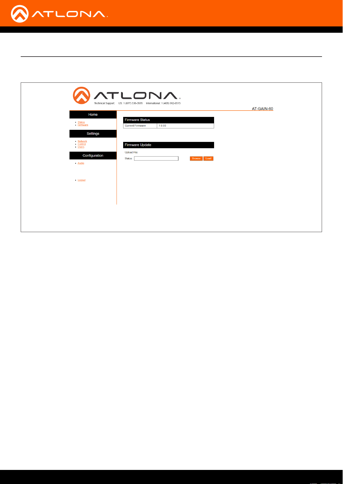
Firmware page
The Web GUI
Current Firmware
The current rmware version installed.
Status (progress bar)
Displays the status of loading new rmware during a rmware update procedure.
Browse
Click this button to select the rmware le. Click the Load button to begin the update procedure. Refer to Updating
the Firmware (page 34) for more information.
Load
Click this button to upload the selected rmware le to the AT-GAIN-60. While the system settings le is being
loaded, the Status progress bar will display the current progress.
AT-GAIN-60
27

The Web GUI
Network page
After pressing the Save button, a reboot message will appear at the top of the web GUI. The AT-GAIN-60 must be
rebooted when any of the network settings have changed.
DHCP
Click the ON button to enable DHCP. Click the OFF button to enable static IP mode. In static IP mode, the IP
Address, Subnet, and Gateway elds can be modied.
IP Address
Enter the IP address of the AT-GAIN-60 in this eld. This eld can only be changed when DHCP is set to OFF.
Subnet
Enter the subnet mask in this eld. This eld can only be changed when DHCP is set to OFF.
Gateway
Enter the gateway (router) IP address in this eld. This eld can only be changed when DHCP is set to OFF.
Telnet Port
Enter the Telnet listening port in this eld. The default port is 23.
HTTP Port
Enter the HTTP listening port in this eld. The default port is 80. This eld cannot be modied.
IP Timeout
Enter the time-out interval (in seconds) in this eld.
This eld represents the time interval before the TCP/IP connection times out.
Hostname
Enter the desired hostname in this eld. By default, the hostname is the product (SKU) plus the last ve digits of the
unit serial number.
AT-GAIN-60
28

The Web GUI
Telnet Login Mode
Click the ON button to prompt for username and password credentials. Username and password credentials are the
same as the web GUI login credentials. Click the OFF button to create an open Telnet session that does not require
login credentials. The default setting is OFF.
Save / Cancel
Click the Save button after any changes have been made. Click the Cancel button to abort changes.
AT-GAIN-60
29

Control page
The Web GUI
Power
Click the ON button to power-on the AT-GAIN-60. Click the OFF button to power-o the unit.
Auto Power On
Settings this feature to ON will automatically power-on the AT-GAIN-60 when an incoming audio signal is detected.
The default setting is ON. Refer to Auto Power On mode (page 22) for more information.
Auto Power Down
Enables or disables auto power down mode. Refer to Auto Power Down mode (page 22) for more information.
Auto Power Down Time (min)
Specify the time interval before the AT-GAIN-60 goes into auto power down mode. Refer to Auto Power Down mode
(page 22) for more information. The default setting is 15 minutes.
Factory Default
Click this button to reset the AT-GAIN-60 to factory-default settings.
Blink
Click the Blink button to start blinking the PWR LED indicator. This feature is useful to identify the unit when multiple
units are being used.
Front Panel
Click to lock or unlock the buttons on the front panel. Locking the front panel buttons is useful in preventing
accidental button activation within rack environments.
AT-GAIN-60
30

The Web GUI
RS-232
Sets the RS-232 settings used by the control device. The default settings are 115200, 8, None, 1.
Setting Description
Baud rate Sets the baud rate. The following options are available:
110, 300, 600, 1200, 2400, 4800, 9600, 14400, 19200, 38400, 57600, 115200.
Data bit Sets the number of data bits used to represent each character of data. The following
options are available: 5, 6, 7, or 8.
Parity Sets the parity bit, which can be included with each character to detect errors during
the transmission of data. The following options are available: None, Odd, or Even.
Stop bit Sets the stop bit. Stop bits are sent at the end of each character, allowing the client to
detect the end of a character stream. The following options are available: 1 or 2.
AT-GAIN-60
31

Users page
The Web GUI
Current Username
The administrator username. This eld cannot be changed.
Password
Enter the password for the administrator in this eld. Special characters (e.g. #, %, @, &, etc.) are not permitted.
Change Admin Password
• Old password
Enter the current password in this eld. The default password is Atlona.
• New Password
Enter the new password in this eld.
• Conrm Password
Verify the new password by entering it in this eld.
Save / Cancel
Click the Save button to apply all changes. Click the Cancel button to abort changes.
AT-GAIN-60
32

Audio page
The Web GUI
Input Selection
Click this drop-down list to select the audio input: Balance or Unbalance. Select the Balance option to set the
active audio input to the AUDIO IN 1 port. Select the Unbalance option to set the AUDIO IN 2 port the active audio
input.
Equalization
Click and drag the Bass and Treble sliders to the desired settings. The Bass and Treble sliders have a range from
-10 to +10. Click and drag the Volume slider to adjust the output volume to the desired level. Volume can be
adjusted from 0 to 100. Note that the output volume is not measured in decibels. The default value is 30.
Auto Reset
Click this button to reset the Bass, Treble, and Volume to the default settings. Refer to Default Settings (page 39)
for more information.
Mute
Click this button to mute the audio output.
AT-GAIN-60
33

Appendix
Updating the Firmware
The AT-GAIN-60 can only be updated through the web GUI.
IMPORTANT: As of this writing, Google Chrome is the only browser that is supported for rmware
updates. Other browsers will be supported in future versions of rmware.
Required items:
• Firmware
• IP address of the AT-GAIN-60
• Computer on the same network as the AT-GAIN-60
• Username and password to access the web GUI
1. Verify that an Ethernet cable is connected between the AT-GAIN-60 and the network. The computer used to
access the web GUI must be on the same network as the AT-GAIN-60.
2. Type the IP address of the AT-GAIN-60 into the web browser, as shown in the example below.
3. The login screen will be displayed. Login using the username and password. The default login credentials are:
Username: admin
Password: Atlona
AT-GAIN-60
34

Appendix
4. Click Status in the menu bar on left side of the screen.
5. Click the Save button.
6. The Save As dialog box will be displayed. Select the folder where the le will be saved. Click the Save button to
save the le. The le is saved in .bin format and uses the default name of systemsettings.bin.
7. Click Firmware on the left side of the screen.
8. Click the Browse button to select the rmware le.
9. Click the Load button to begin the upgrade process. Once the update has been completed, the login screen will
be displayed.
AT-GAIN-60
WARNING: Power must not be disconnected or interrupted during the rmware update process.
35

Appendix
Rack Mount Installation
The AT-GAIN-60 can be mounted in dierent ways, based on the number of units that are being installed.
In order to rack-mount the AT-GAIN-60, the AT-RACK-1RU will need to be purchased from atlona.com.
The AT-RACK-1RU can be used to either mount three AT-GAIN-60 unit at once or it can be used to mount two ATGAIN units.
IMPORTANT: Before mounting the AT-GAIN-60 to the AT-RACK-1RU, remove the rubber feet from
the bottom of the unit.
Mounting three AT-GAIN-60 units
1. Turn the AT-GAIN-60 so that the
bottom of the unit is facing upward.
2. Locate the two sets of holes on
either side of the unit, as shown.
AT-RACK-1RU
BOTTOM
Mounting Holes
AT-GAIN-60
Front of unit
36

Appendix
3. Mount each of the AT-GAIN-60 units in the rack. Match the mounting holes on the bottom of each AT-GAIN-60
with the holes in the rack tray, marked in the illustration below.
TOP
Front of rack tray
4. Install the rack tray in the rack shelf and secure the rack tray with two screws on either side.
IMPORTANT: To prevent possible damage
to the device, rack, and/or screws, do not
overtighten or use high-torque devices
when securing the devices to the rack.
AT-GAIN-60
37

Appendix
Mounting two AT-GAIN-60 units
The following provides an alternate method for mounting AT-GAIN-60 units closer together. This option provides
extra space in the AT-RACK-1U for cabling, etc.
1. Turn the AT-GAIN-60 so that the bottom of the unit is facing upward.
2. Locate the two sets of holes on either side of the unit. Refer to Rack Mount Installation (page 36) for the
location of the mounting holes.
3. Mount each of the AT-GAIN-60 units in the rack. Match the mounting holes on the bottom of each AT-GAIN-60
with the holes marked in the illustration below.
TOP
Front of rack tray
4. Install the rack tray in the rack shelf and secure the rack tray with two screws on either side.
IMPORTANT: To prevent possible damage
to the device, rack, and/or screws, do not
overtighten or use high-torque devices
when securing the devices to the rack.
AT-GAIN-60
38

Default Settings
The following table lists the factory-default settings for the AT-GAIN-60.
Feature Settings
Appendix
Network DHCP
Static IP address
Subnet
Gateway
Telnet Port
HTTP Port
IP Timeout
Hostname
Telnet Login Mode
Control Power
Auto Power On
Auto Power Down
Auto Power Down Timer (min)
Blink
Lock
RS-232
Users Admin username
Admin password
Audio Input Selection
Equalization bands
Bass
Treble
Volume
ON
192.168.1.254
255.255.0.0
192.168.1.1
23
80
300
AT-GAIN-60-[last ve digits of serial number]
OFF
OFF
ON
ON
15
Disabled
UNLOCK
Baud rate
Data bits
Parity
Stop bits
admin
Atlona
Balance
0
0
30
115200
8
None
1
AT-GAIN-60
39

Specications
Connectors, Controls, and
Indicators
LAN 1 - RJ45
AUDIO IN 1 1 - 5-pin captive screw, balanced: 10 kΩ
AUDIO IN 2 2 - RCA-type, female, unbalanced: 20 kΩ
4 / 8 Ω OUT 1 - 4-pin, 5.08 mm lock-down screw connector
24 / 70 / 100V 1 - 5-pin, 3.5mm
Power 1 - 3.5 mm barrel, locking
INPUT GAIN 1 - Rotary pot
MODE 1 - Slider switch, 5-pole, 24V / 70V / 100V / 8 Ω / 4 Ω
RESET 1 - Push button, tact-type
INPUT 1 - Push button, tact-type
MUTE 1 - Push button, tact-type
VOL 2 - Push buttons, tact-type
PWR 1 - LED indicator, green
1 / 2 Input Indicators 2 - LED indicators, green
Mute Indicator 1 - LED indicator, red
Audio Level Indicator 1 - Multi-LED
Appendix
Input Signal
Analog Input Balanced: 20 kΩ, unblanced: 10 kΩ
Input Gain Adjustable, -22 dB to 0 dB
CMRR 49 dB / 67 dB
Detection Threshold 0 dBV = 2.218 dBu
Output Signal
Distributed speakers (mono) 24 V / 70 V / 100 V
Program speakers (stereo) 4 Ω / 8 Ω, line-level
Power 24 V = 60 Vrms (high-Z)
70 V = 60 Vrms (high-Z)
100 V = 60 Vrms (high-Z)
4 / 8 Ω = 30 W per channel
Audio Processing
Audio Formats 24-bit uncompressed, selectable at 44.1,48, 88.2, and 96 kHz sampling rate
Signal Processing Volume, Auto on/off signal sensing, 80 Hz HPF
2-band EQ Bass / Treble, adjustable: -10 to +10 dB
AT-GAIN-60
40

Appendix
Audio Performance
Frequency Response 20 Hz - 20 kHz, ±0.2 / - 2 dB @ 4 Ω load
THD + N < 0.1% @ 1 kHz, 3 db below clipping
SNR > 95 dBA WTD
Damping Factor < 48 @ 8 Ω
Amplier Type Class D
Temperature Fahrenheit Celsius
Operating 32 °F to 122 °F 0 °C to 50 °C
Storage -40 °F to 158 °F -40 °C to 70 °C
Humidity (RH) 90% RH, non-condensing
Power
Standby Mode Powers down after 5 - 25 minutes (adjustable) of no signal; complies with ENERGY
STAR power consumption limits of < 0.5 W in standby mode
Consumption 60 W (max.)
Standby Consumption < 1.2 W
Supply 100 - 240 V AC, 50/60 Hz, 60 W
Dimensions Inches Millimeters
H x W x D 1.69 x 5.00 x 7.95 43 x 127 x 202
Weight Pounds Kilograms
Device 3.15 1.43
Certication
Device CE, RoHS, WEEE, FCC, ENERGY STAR
®
AT-GAIN-60
41

Index
A
Appendix 31
Audio
connectors 11
distributed speakers 11
impedance 11
Auto power-down. SeePower modes
C
Conguration
IP. SeeIP conguration
Connection
diagram 14
instructions 13
Contents
package 9
Customer support 3
D
Default setttings 36
Description
front / rear panel 10
auto power-down 20
powering on/o 20
R
Rack mount
installation 33
Resetting
to factory-default 21
S
Safety information 6
Specications 37
U
Users
primary user name 22
W
Warranty 4
Web GUI 22
F
FCC statement 7
Features 9
Firmware
displaying 24, 25
I
Installation 11
IP conguration
using commands 16
using rear panel 15
using the web GUI 17
L
LED indicators 19
O
Operating notes 3
P
Panel descriptions 10
Password
changing 29
default 22
Power modes
AT-GAIN-60
42

atlona.com • 408.962.0515 • 877.536.3976
© 2018 Atlona Inc. All rights reserved. “Atlona” and the Atlona logo are registered trademarks of Atlona Inc. All other brand names and trademarks or registered trademarks are the property of their respective owners. Pricing, specications and availability
subject to change without notice. Actual products, product images, and online product images may vary from images shown here.
 Loading...