

Page 1

Installation Guide
AT-GAIN-120
Stereo/Mono Audio Power Amplier - 120 Watts
AT-GAIN-120
The Atlona Gain™ 120 (AT-GAIN-120) is a compact power amplier designed for low or high
impedance applications. A mode selector switch allows it to deliver two channels of 60 watts
each into 4 or 8 ohms, or a single channel of 120 watts at 70 or 100 volts. This Class-D amplier
is energy ecient, ENERGY STAR® qualied, and is also convection-cooled to allow installation
in conference rooms and quiet installation environments without the need for fans. In addition to
the amplied speaker output, a line level audio output allows the incoming audio to be fed into an
additional amplier or audio system. The Gain 120 is controllable via TCP/IP or external trigger,
and can be integrated with Atlona AV switchers and HDBaseT™ receivers for a wide variety of
sound reinforcement applications.
Package Contents
1 x AT-GAIN-120
2 x Captive screw connector, 2-pin
1 x Captive screw connector, 4-pin
2 x Captive screw connector, 5-pin
1 x IEC power cord
1 x Installation Guide
IMPORTANT: Visit http://www.atlona.com/product/AT-GAIN-120 for the latest rmware
updates and User Manual.
1
Page 2
Installation Guide
PWR
VOL LEVEL
AUDIO AMPLIFIER
FWSIGNAL ANALOG IN
NET AUDIODEVICE ID
GAIN
TM
AT-GAIN-120
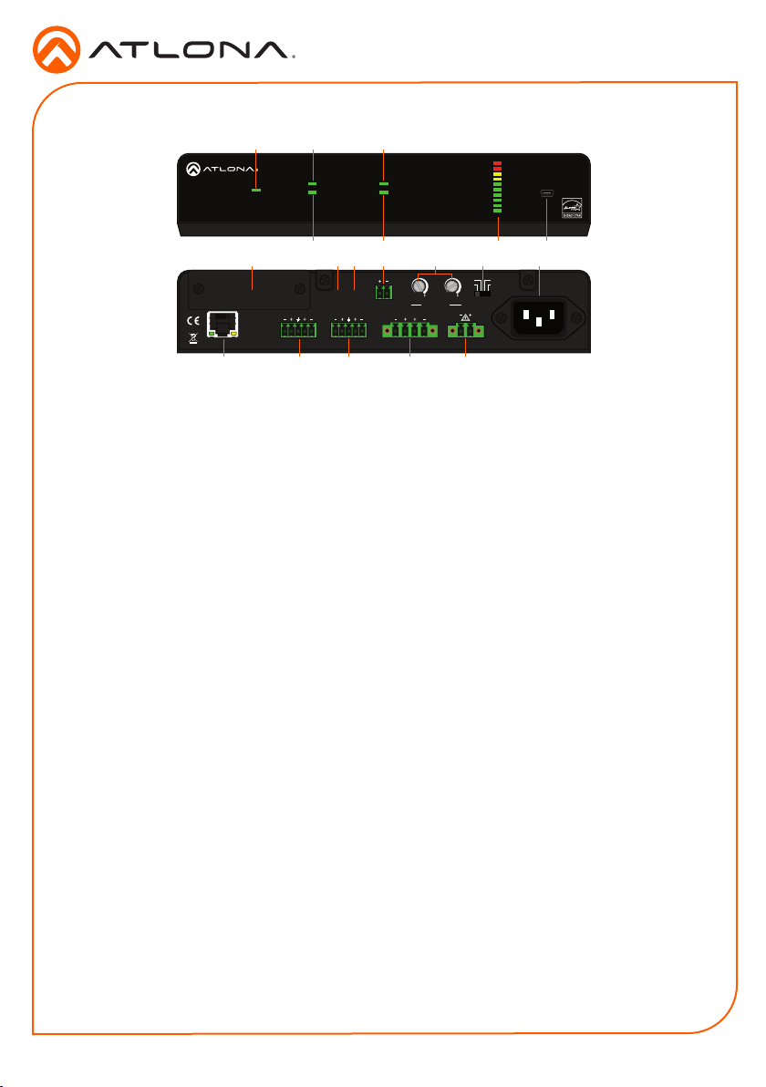
Front Panel Descriptions
1 2 3
PWR
TM
GAIN
L
LAN
ANALOG IN
NET AUDIODEVICE ID
4 5 6 7
98 10 11 141312
IP
RESET RESET
R
L R L R
LINE OUT
L R
-9
-9
-4
-4
8Ω 100V
-2
-14
-19
TRIGGER MODE
4 / 8 Ω OUT 70V / 100V OUT
CLASS 2 WIRING CLASS 2 WIRING
-2
-14
4Ω
-19
-20
-20
-22
-22
dB
dB
INPUT GAIN
1615 17 18 19
1 PWR
This LED will indicate power status.
2 SIGNAL
Will illuminate when an audio source or
signal is detected.
3 ANALOG IN
The LED will illuminate green when the
ANALOG IN port is the active input port.
4 DEVICE ID
LED will blink when the command Blink on
is sent, to help identify the device when
multiple units are present.
5 NET AUDIO (Optional function)
LED will illuminate when the INPUT port,
available on the optional AT-GAIN-NET
card, is the active input port.
6 VOL LEVEL
Displays the output audio level.
7 FW
Connect a USB-to-mini USB cable to
this port from a computer for rmware
updates.
8 Removable Faceplate
Insert the optional AT-GAIN-NET into this
slot.
9 RESET
Press and hold button for 10 seconds to
factory reset the unit.
10 IP RESET
Press and hold button for 10 seconds
to switch between DHCP and static IP
mode. Also press and hold for 3 seconds
to bring the unit out of hibernation mode.
11 TRIGGER
Use this port to toggle the unit between
on and standby or awaken the unit from
hibernation mode.
12 INPUT GAIN
Use a screwdriver to adjust the input gain
level for left and right channel.
13 MODE
Slide the switch to select between 4Ω, 8Ω,
70V, or 100V speaker power modes.
14 PWR
Connect from a power source to the ATGAIN-120 using the included IEC power
cord.
15 LAN
Connect an Ethernet cable to this port
from the Local Area Network.
16 ANALOG IN
Connect an audio source to this port
using the included 5-pin captive screw
connector.
17 LINE OUT
Use the included 5-pin captive screw
connector to connect to another AT-
GAIN-120, audio DSP, or audio mixer.
18 4 / 8 Ω OUT
Connect a pair of 4 or 8 ohm speakers to
this port using the included 4 pin captive
screw connector.
19 70V / 100V OUT
Connect 70V or 100V speakers to this
port with the included 2-pin captive screw
connector.
VOL LEVEL
70V
PWR: 100-120VAC 60Hz 120W
AUDIO AMPLIFIER
FWSIGNAL ANALOG IN
MODEL:
AT-GAIN-120
220-240VAC 50Hz 120W
2
Page 3

Installation Guide
L R
L R
L R
L R
Analog In
Connect to an audio DSP or other audio distribution or source devices. Either balanced or
unbalanced connections may be used.
L R
ANALOG IN
+
-
Negative
Positive
Ground
+
-
Negative
Positive
+
Positive
Ground
Use a jumper between the
negative and ground pins
when using an unbalanced
connection.
+
Positive
AT-GAIN-120
Line Out
Balanced
Unbalanced
Connect to another GAIN-120 amplier audio input, audio mixer, or DSP.
L R
+
LINE OUT
Speaker Out
8Ω 100V
4Ω
70V
MODE
+
-
Negative
Positive
Positive
Ground
-
Negative
Balanced
Only one speaker output mode can be used at one time. Use the mode switch
to select the correct power mode.
+
+
Positive
Positive
Ground
Unbalanced
The 4-pin captive screw connector will be used with
either 4 or 8 ohm speakers. Slide the mode switch
to 4 or 8 ohm depending on the speaker type.
4 / 8 Ω OUT
CLASS 2 WIRING
The 2-pin captive screw connector will be used with
either 70V or 100V speakers. Slide the mode switch to
70V or 100V depending on the speaker type.
70V / 100V OUT
CLASS 2 WIRING
Use a jumper between the
negative and ground pins
when using an unbalanced
connection.
Trigger
TRIGGER
The GAIN-120 can be toggled between on and standby using a
control device and system, such as the Velocity Command Converter
and Velocity control software. Connect the GAIN-120 using the
included 2-pin captive screw connector.
3
Page 4

Installation Guide
AT-GAIN-120
Installation
1. Connect an audio source into the ANALOG IN port using the included 5-pin captive screw
connector.
2. Connect speakers to either the 4 / 8 Ohm or 70V / 100V port.
3. Set the mode switch to the correct output mode.
NOTE: Gain-120 only supports one powered speaker type (low or high
impedance) output port at a time.
4. *Optional* Connect the line out to another GAIN-120’s ANALOG IN port for additional
speaker zones or an audio DSP.
5. *Optional* Connect the included 2-pin captive screw connector to the Trigger port to toggle
the GAIN-120 between on and standby mode, or to awake from hibernation mode, see ATGAIN-120 user manual for information on hibernation mode.
6. *Optional* Install the AT-GAIN-NET audio network card (not included) to accept Dante/
AES67 audio.
7. Connect the LAN port to a network switch for set up and control of the unit.
8. Connect the IEC cable from the unit to a 120V-240V power source.
Mounting Instructions
The AT-GAIN-120 can be mounted in dierent
ways, based on the number of units that are being
installed. When installed into a standard 19” rack,
the AT-RACK-1RU will need to be purchased from
atlona.com.
AT-RACK-1RU
When installing the AT-GAIN-120 into the AT-RACK-1RU, it can be installed as a single unit on
either side of the rack or paired with any of Atlona’s other 1/2 rack units. e.g. UHD-SW series
products or another AT-GAIN-120
1. Turn the rack and unit upside down.
2. Line up the AT-GAIN-120 mounting holes to the holes marked with blue on the rack image
on the next page.
3. Use the included 7 mm screws to ax the unit to the rack.
4
Page 5

PWR
VOL LEVEL
AUDIO AMPLIFIER
FWSIGNAL ANALOG IN
NET AUDIODEVICE ID
GAIN
TM
LAN
INPUT
NETWORK AUDIO
RESET RESET
LINE OUT
CLASS 2 WIRING CLASS 2 WIRING
TRIGGER MODE
MODEL:
dB
-22
-2
-4
-20
-19
-14
-9
-22
-2
-4
-20
-19
-14
-9
dB
ANALOG IN
L
4 / 8 Ω OUT 70V / 100V OUT
AT-GAIN-120
PWR: 100-120VAC 60Hz 120W
220-240VAC 50Hz 120W
L R
IP
4Ω
8Ω 100V
70V
R
INPUT GAIN
L R
NOTE: Do not over-tighten the rack screws
-GAIN-120
to avoid damaging the unit.
Installation Guide
AT-GAIN-120
ANALOG IN
VOL LEVEL
LINE OUT
L
R
CLASS 2 WIRING CLASS 2 WIRING
4 / 8 Ω OUT 70V / 100V OUT
L R
RESET RESET
NETWORK AUDIO
IP
TRIGGER MODE
NET AUDIODEVICE ID
PWR: 100-120VAC 60Hz 120W
220-240VAC 50Hz 120W
INPUT GAIN
dB
-22
-20
-19
dB
-14
-22
-20
-9
-19
-2
L R
-4
-14
TM
GAIN
-9
4Ω
PWR
-2
-4
8Ω 100V
LAN
ANALOG IN
VOL LEVEL
INPUT
FWSIGNAL ANALOG IN
LINE OUT
L
AUDIO AMPLIFIER
R
CLASS 2 WIRING CLASS 2 WIRING
4 / 8 Ω OUT 70V / 100V OUT
L R
RESET RESET
NETWORK AUDIO
IP
TRIGGER MODE
NET AUDIODEVICE ID
PWR: 100-120VAC 60Hz 120W
220-240VAC 50Hz 120W
INPUT GAIN
dB
-22
-20
-19
dB
-14
-22
-20
-9
-19
-2
L R
-4
-14
TM
GAIN
PWR
MODEL:
AT
4. Turn the rack and units right-side up and install into a rack using the screws included with
the rack.
5
-9
4Ω
-2
-4
8Ω 100V
70V
70V
MODEL:
AT-GAIN-120
LAN
INPUT
FWSIGNAL ANALOG IN
AUDIO AMPLIFIER
Page 6

Installation Guide
AT-GAIN-120
IP Modes
DHCP
By default, the AT-GAIN-120 is set to DHCP mode. In this mode, when the AT-GAIN-120 is
connected to the Local Area Network (LAN), it will automatically be assigned an IP address by
the DHCP server (if available).
Static
If no DHCP server is available, or a static IP is required, the GAIN-120 can be set to static IP
mode using the IP reset button.
• Press and hold the IP RESET button for 10 seconds to switch to static IP mode. In this
mode, the AT-GAIN-120 will be set to the following:
IP address: 192.168.1.254
Subnet mask 255.255.0.0
Gateway: 192.168.1.1
• To switch back to DHCP, press and hold the IP reset button for 10 seconds.
Accessing the webGUI
The AT-GAIN-120 includes a built-in webGUI, which allows easy remote management and control
of all features. Follow the instructions below to access the webGUI.
1. Make sure that an Ethernet cable is connected between the LAN port on the AT-GAIN-120
and the network.
2. Launch a web browser and enter the IP address of the unit.
3. The AT-GAIN-120 Login page will be displayed.
4. Enter the following information on the Login page.
Login: admin
Password: Atlona
5. Click the Login button.
6. Refer to User Manual for detailed operation of the webGUI.
AMS 2.0
For easy conguration of Atlona devices , AMS 2.0 is available from https://atlona.com/ams for
free. Two options can be used for installation: The free Linux based software download or the
easy to install server hardware (AT-AMS-HW).
Once AMS has been set up:
1. Open a browser on the same network as AMS 2.0 and go to the IP address of AMS 2.0.
View the AMS 2.0 installation instructions on how to nd the IP address of the software.
2. Enter the login information on the AMS 2.0 web page, then click the Login button.
3. View the AT-GAIN-120 manual for routing and conguration information.
6
Page 7

Connection Diagram
Installation Guide
AT-GAIN-120
Laptop
4 / 8 Ohm Out
Line Out
Analog Audio
Speakers
70 / 100 Volt Out
Generic
SPEAKER SYSTEMSSPEAKER SYSTEMS
Generic
SPEAKER SYSTEMSSPEAKER SYSTEMS
Ceiling
AUDIO AMPLIFIER
FWSIGNAL
VOL LEVEL
ANALOG IN
NET AUDIO
DEVICE ID
PWR
AT-GAIN-120
TM
GAIN
AUDIO AMPLIFIER
FWSIGNAL ANALOG IN
VOL LEVEL
NET AUDIODEVICE ID
PWR
AT-GAIN-120
TM
GAIN
Speakers
7
Page 8

Installation Guide
AT-GAIN-120
Version 2
atlona.com • 408.962.0515 • 877.536.3976
© 2018 Atlona Inc. All rights reserved. “Atlona” and the Atlona logo are registered trademarks of Atlona Inc. All other brand names and trademarks or registered
trademarks are the property of their respective owners. Pricing, specications and availability subject to change without notice. Actual products, product images, and
online product images may vary from images shown here.
8
 Loading...