

Atlona AT-OMNI-324, OmniStream 324, OmniStream AT-OMNI-311 Installation Manual

1
Installation Guide
AT-OMNI-324
USB to IP Adapter for Peripheral Devices
AT-OMNI-324
The Atlona OmniStream™ 324 (AT-OMNI-324) works in tandem with the OmniStream 311
(AT-OMNI-311) for extending USB from peripheral devices to a PC over Gigabit Ethernet. The
OmniStream 324 features a four-port USB hub for peripherals, while the OmniStream 311
interfaces with a PC or other host device. The OmniStream USB over IP system is compatible
with USB 2.0 data rates of up to 480 Mbps. It can be used with high-bandwidth devices including
cameras, speakerphones, microphones, and DSPs, plus standard USB HID class devices
such as a keyboard, mouse, or touch display. Up to seven OmniStream 324 units can be
simultaneously paired to an OmniStream 311. Additionally, USB routing over the network can be
managed using Atlona Management System (AMS) 2.0.
OmniStream USB products can be used in a wide variety of system design scenarios for soft
codec conferencing and remote keyboard / mouse control. They are ideal for integrating USB
audio and video devices as part of a fully IP-based meeting room system, in conjunction with
OmniStream AV over IP devices and the Velocity Control System.
IMPORTANT: Visit http://www.atlona.com/product/AT-OMNI-324 for the latest rmware
updates and Installation Guide.
Package Contents
1 x AT-OMNI-324
1 x 24 V DC power supply
2 x Mounting brackets
1 x Installation Guide
2
Installation Guide
AT-OMNI-324
HOST
LINK
PWR
O
MNI
S
TREAM
TM
SIGNAL
USB
USB
USB
USB
LAN
PAIRING
UTILITY
AT-OMNI-324
DC 24V
LAN
PAIRING
UTILITY
AT-OMNI-324
DC 24V
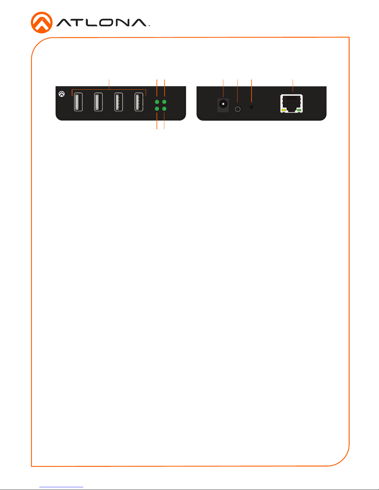
Panel Descriptions
1 USB Device Ports
Connect up to four USB devices using these ports.
2 PWR
This LED indicator glows solid green when the unit is powered. This unit is powered by the host device
using USB. No external power supply is required. Refer to LED Indicators (page 6) for more
information.
3 HOST
This LED indicator glows green when a USB host device is connected to the AT-OMNI-311 (not included).
Refer to LED Indicators (page 6) for more information.
4 LINK
This LED indicator is solid green when a solid connection between this unit and the transmitter has been
established. Refer to LED Indicators (page 6) for more information.
5 SIGNAL
This LED indicator monitors data transmission between this unit and the receiver. The LED will blink
intermittently whether or not a USB device is connected. Refer to LED Indicators (page 6) for
more information.
6 DC 24V
Connect the included power supply to this power receptacle.
7 UTILITY
This port is for factory programming.
8 PAIRING
Press this button to begin the pairing process.
9 LAN
Connect an Ethernet cable from this port to the Local Area Network (LAN).
Front Rear
76 821 3
4 5
9
3
Installation Guide
AT-OMNI-324
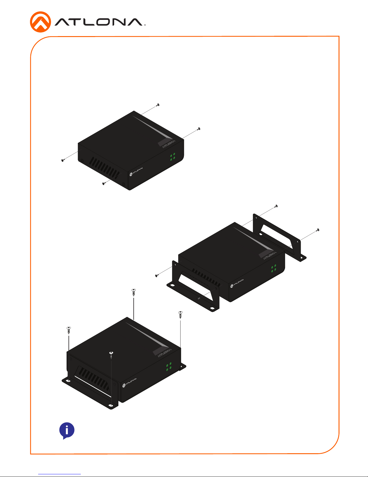
The AT-OMNI-324 includes two mounting brackets, which can be used to attach the units to any
at surface.
1. Remove the two enclosure screws, on both sides of the unit, using a small Phillips-head
screwdriver.
2. Position one of the mounting brackets, as shown below, aligning
the holes on the side of the enclosure with one set of holes on
the mounting bracket.
3. Attach the mounting brackets using the
enclosure screws from Step 1.
4. Mount the unit using the ovalshaped holes, on each mounting
bracket. If using a drywall
surface, a #6 drywall screw is
recommended.
Mounting Instructions
PWR
LINK
SIGNAL
HOST
O
MNI
S
TREAM
TM
NOTE: The unit can also be mounted under a table or other at surface.
PWR
LINK
SIGNAL
HOST
O
MNI
S
TREAM
TM
PWR
LINK
SIGNAL
HOST
O
MNI
S
TREAM
TM
 Loading...