

Atlona OmniStream AT-OMNI-121, OmniStream AT-OMNI-122 User Manual

OmniStream
™
Single-Channel / Dual-Channel
Networked AV Decoder
AT-OMNI-121
AT-OMNI-122
Atlona Manuals
Networked AV

Version Information
Version Release Date Notes
1 04/17 Initial release
2 06/17 New enclosure, documentation updates: AMS interface; front-panel buttons,
decoder set tab
3 12/17 Video wall conguration plus bezel compensation, slate / logo insertion, text
insertion, redundancy grace period for IP input changes
4 05/18 Updated to reflect AMS 2.0
5 07/18 Includes updates to 1.2.1 firmware; AMS updates
6 10/18 1.2.2 firmware; Dolby Vision decoding/licensing, fast switching
AT-OMNI-121 / AT-OMNI-122
2

Welcome to Atlona!
Thank you for purchasing this Atlona product. We hope you enjoy it and will take a extra few moments to register
your new purchase.
Registration only takes a few minutes and protects this product against theft or loss. In addition, you will receive
notications of product updates and rmware. Atlona product registration is voluntary and failure to register will not
aect the product warranty.
To register your product, go to http://www.atlona.com/registration
Sales, Marketing, and Customer Support
Main Oce
Atlona Incorporated
70 Daggett Drive
San Jose, CA 95134
United States
Oce: +1.877.536.3976 (US Toll-free)
Oce: +1.408.962.0515 (US/International)
Sales and Customer Service Hours
Monday - Friday: 6:00 a.m. - 4:30 p.m. (PST)
http://www.atlona.com/
International Headquarters
Atlona International AG
Ringstrasse 15a
8600 Dübendorf
Switzerland
Oce: +41 43 508 4321
Sales and Customer Service Hours
Monday - Friday: 09:00 - 17:00 (UTC +1)
Operating Notes
• The Atlona Management System (AMS) is a free downloadable application from Atlona that provides network
conguration assistance for this product. This application is available only for the Windows® Operating System
and can be downloaded from the Atlona web site.
IMPORTANT: Visit http://www.atlona.com/product/AT-OMNI-121 and http://www.atlona.com/
product/AT-OMNI-122 for the latest rmware updates and User Manual.
NOTE: Scaling and deinterlacing is not supported at 1080i.
©2019 Atlona, Inc. All Rights Reserved. All trademarks are the property of their respective owners.
Atlona reserves the right to make changes to the hardware, packaging, and documentation without notice.
AT-OMNI-121 / AT-OMNI-122
3

Atlona, Inc. (“Atlona”) Limited Product Warranty
Coverage
Atlona warrants its products will substantially perform to their published specications and will be free from defects
in materials and workmanship under normal use, conditions and service.
Under its Limited Product Warranty, Atlona, at its sole discretion, will either:
• repair or facilitate the repair of defective products within a reasonable period of time, restore products to their
proper operating condition and return defective products free of any charge for necessary parts, labor and
shipping.
OR
• replace and return, free of charge, any defective products with direct replacement or with similar products
deemed by Atlona to perform substantially the same function as the original products.
OR
• refund the pro-rated value based on the remaining term of the warranty period, not to exceed MSRP, in cases
where products are beyond repair and/or no direct or substantially similar replacement products exist.
Repair, replacement or refund of Atlona products is the purchaser’s exclusive remedy and Atlona liability does not
extend to any other damages, incidental, consequential or otherwise.
This Limited Product Warranty extends to the original end-user purchaser of Atlona products and is non-transferrable
to any subsequent purchaser(s) or owner(s) of these products.
Coverage Periods
Atlona Limited Product Warranty Period begins on the date of purchase by the end-purchaser. The date contained on
the end-purchaser ‘s sales or delivery receipt is the proof purchase date.
Limited Product Warranty Terms – New Products
• 10 years from proof of purchase date for hardware/electronics products purchased on or after June 1, 2013.
• 3 years from proof of purchase date for hardware/electronics products purchased before June 1, 2013.
• Lifetime Limited Product Warranty for all cable products.
Limited Product Warranty Terms – Refurbished (B-Stock) Products
• 3 years from proof of purchase date for all Refurbished (B-Stock) hardware and electronic products purchased
on or after June 1, 2013.
Remedy
Atlona recommends that end-purchasers contact their authorized Atlona dealer or reseller from whom they
purchased their products. Atlona can also be contacted directly. Visit www.atlona.com for Atlona’s contact
information and hours of operation. Atlona requires that a dated sales or delivery receipt from an authorized dealer,
reseller or end-purchaser is provided before Atlona extends its warranty services. Additionally, a return merchandise
authorization (RMA) and/or case number, is required to be obtained from Atlona in advance of returns.
Atlona requires that products returned are properly packed, preferably in the original carton, for shipping. Cartons not
bearing a return authorization or case number will be refused. Atlona, at its sole discretion, reserves the right to reject
any products received without advanced authorization. Authorizations can be requested by calling 1-877-536-3976
(US toll free) or 1-408- 962-0515 (US/international) or via Atlona’s website at www.atlona.com.
Exclusions
This Limited Product Warranty excludes:
• Damage, deterioration or malfunction caused by any alteration, modication, improper use, neglect, improper
packaging or shipping (such claims must be presented to the carrier), lightning, power surges, or other acts of
nature.
AT-OMNI-121 / AT-OMNI-122
4

Atlona, Inc. (“Atlona”) Limited Product Warranty
• Damage, deterioration or malfunction resulting from the installation or removal of this product from any
installation, any unauthorized tampering with this product, any repairs attempted by anyone unauthorized by
Atlona to make such repairs, or any other cause which does not relate directly to a defect in materials and/or
workmanship of this product.
• Equipment enclosures, cables, power supplies, batteries, LCD displays, and any accessories used in conjunction
with the product(s).
• Products purchased from unauthorized distributors, dealers, resellers, auction websites and similar unauthorized
channels of distribution.
Disclaimers
This Limited Product Warranty does not imply that the electronic components contained within Atlona’s products
will not become obsolete nor does it imply Atlona products or their electronic components will remain compatible
with any other current product, technology or any future products or technologies in which Atlona’s products may
be used in conjunction with. Atlona, at its sole discretion, reserves the right not to extend its warranty oering in
instances arising outside its normal course of business including, but not limited to, damage inicted to its products
from acts of god.
Limitation on Liability
The maximum liability of Atlona under this limited product warranty shall not exceed the original Atlona MSRP for
its products. To the maximum extent permitted by law, Atlona is not responsible for the direct, special, incidental or
consequential damages resulting from any breach of warranty or condition, or under any other legal theory. Some
countries, districts or states do not allow the exclusion or limitation of relief, special, incidental, consequential or
indirect damages, or the limitation of liability to specied amounts, so the above limitations or exclusions may not
apply to you.
Exclusive Remedy
To the maximum extent permitted by law, this limited product warranty and the remedies set forth above are
exclusive and in lieu of all other warranties, remedies and conditions, whether oral or written, express or implied.
To the maximum extent permitted by law, Atlona specically disclaims all implied warranties, including, without
limitation, warranties of merchantability and tness for a particular purpose. If Atlona cannot lawfully disclaim
or exclude implied warranties under applicable law, then all implied warranties covering its products including
warranties of merchantability and tness for a particular purpose, shall provide to its products under applicable law.
If any product to which this limited warranty applies is a “Consumer Product” under the Magnuson-Moss Warranty
Act (15 U.S.C.A. §2301, ET SEQ.) or other applicable law, the foregoing disclaimer of implied warranties shall not
apply, and all implied warranties on its products, including warranties of merchantability and tness for the particular
purpose, shall apply as provided under applicable law.
Other Conditions
Atlona’s Limited Product Warranty oering gives legal rights, and other rights may apply and vary from country to
country or state to state. This limited warranty is void if (i) the label bearing the serial number of products have been
removed or defaced, (ii) products are not purchased from an authorized Atlona dealer or reseller. A comprehensive
list of Atlona’s authorized distributors, dealers and resellers can be found at www.atlona.com.
AT-OMNI-121 / AT-OMNI-122
5

Important Safety Information
CAUTION
RISK OF ELECTRIC SHOCK
DO NOT OPEN
CAUTION: TO REDUCT THE RISK OF
DO NOT OPEN ENCLOSURE OR EXPOSE
The exclamation point within an equilateral triangle is intended to alert the user to
the presence of important operating and maintenance instructions in the literature
accompanying the product.
The information bubble is intended to alert the user to helpful or optional operational instructions in the literature accompanying the product.
ELECTRIC SHOCK
TO RAIN OR MOISTURE.
NO USER-SERVICEABLE PARTS
INSIDE REFER SERVICING TO
QUALIFIED SERVICE PERSONNEL.
1. Read these instructions.
2. Keep these instructions.
3. Heed all warnings.
4. Follow all instructions.
5. Do not use this product near water.
6. Clean only with a dry cloth.
7. Do not block any ventilation openings. Install in
accordance with the manufacturer’s instructions.
8. Do not install or place this product near any heat
sources such as radiators, heat registers, stoves, or
other apparatus (including ampliers) that produce
heat.
9. Do not defeat the safety purpose of a polarized
or grounding-type plug. A polarized plug has two
blades with one wider than the other. A grounding
type plug has two blades and a third grounding
prong. The wide blade or the third prong are
provided for your safety. If the provided plug does
not t into your outlet, consult an electrician for
replacement of the obsolete outlet.
10. Protect the power cord from being walked on
or pinched particularly at plugs, convenience
receptacles, and the point where they exit from the
product.
11. Only use attachments/accessories specied by
Atlona.
12. To reduce the risk of electric shock and/or damage
to this product, never handle or touch this unit or
power cord if your hands are wet or damp. Do not
expose this product to rain or moisture.
13. Unplug this product during lightning storms or when
unused for long periods of time.
14. Refer all servicing to qualied service personnel.
Servicing is required when the product has been
damaged in any way, such as power-supply cord or
plug is damaged, liquid has been spilled or objects
have fallen into the product, the product has been
exposed to rain or moisture, does not operate
normally, or has been dropped.
FCC Statement
FCC Compliance and Advisory Statement: This hardware device complies with
Part 15 of the FCC rules. Operation is subject to the following two conditions: 1)
this device may not cause harmful interference, and 2) this device must accept any
interference received including interference that may cause undesired operation. This
equipment has been tested and found to comply with the limits for a Class A digital
device, pursuant to Part 15 of the FCC Rules. These limits are designed to provide
reasonable protection against harmful interference in a commercial installation.
This equipment generates, uses, and can radiate radio frequency energy and, if not
installed or used in accordance with the instructions, may cause harmful interference
to radio communications. However there is no guarantee that interference will not occur in a particular installation. If
this equipment does cause harmful interference to radio or television reception, which can be determined by turning
the equipment o and on, the user is encouraged to try to correct the interference by one or more of the following
measures: 1) reorient or relocate the receiving antenna; 2) increase the separation between the equipment and the
receiver; 3) connect the equipment to an outlet on a circuit dierent from that to which the receiver is connected;
4) consult the dealer or an experienced radio/TV technician for help. Any changes or modications not expressly
approved by the party responsible for compliance could void the user’s authority to operate the equipment. Where
shielded interface cables have been provided with the product or specied additional components or accessories
elsewhere dened to be used with the installation of the product, they must be used in order to ensure compliance
with FCC regulations.
AT-OMNI-121 / AT-OMNI-122
6

Table of Contents
Introduction 9
Features 9
Package Contents 9
Panel Description 10
AT-OMNI-121 10
AT-OMNI-122 11
Installation 12
External Power (Optional) 12
RS-232 Connections 13
IR Connections 14
Audio Connectors 15
Connection Instructions 17
Connection Diagram 18
Conguration 19
Discovery using AMS 19
Accessing Decoders in AMS 19
Conguring a Static IP Address 22
Basic Operation 23
LED Indicators 23
Rebooting OmniStream 24
ID Button 24
Broadcast Messaging 24
Factory-Reset using the Front Panel 24
Factory-Reset using RS-232 25
Unicast Mode 26
Multicast Mode 28
Setting the Video Mode 30
Slate / Logo Insertion 31
Deleting Slates / Logos 32
Text Insertion 33
Fast Switching 35
IR Control 36
Controlling the Display using the Display’s IR Remote 36
Required Equipment 37
Connecting the IR Receiver to the Encoder 37
Connecting the IR Emitter to the Decoder 38
Identifying the Encoder using AMS 39
Conguring the Encoder Serial Port 40
Conguring the Encoder Session 41
Conguring the Decoder Serial Port 43
Testing IR Functionality 46
Controlling the Display using a Control System 47
Using the Virtual Matrix 48
Advanced Operation 51
Conguring Audio Output 51
De-embedding Audio 51
Embedding Audio 52
Connecting RS-232 to OmniStream 53
Control Using RS-232 55
RS-232 Pass-Through 55
Triggering Stored Commands 55
Using TCP Proxy 56
AT-OMNI-121 / AT-OMNI-122
7

Table of Contents
Using the Virtual Matrix 57
802.1X Authentication 64
PEAP/MSCHAPv2 Protocol 65
EAP-TLS Protocol 67
AES67 Audio 69
Scrambling 72
Standard Method 72
Using the Virtual Matrix 73
Creating Video Walls 75
Bezel Compensation 81
Video Walls using Velocity 82
Creating and Using Drop Zones 91
Custom Drop Zones 97
Conguring Redundant Streams 100
Redundancy Grace Period 101
The AMS Interface 102
Device Info page 102
SAP page 105
IP Input page 106
HDMI Output page 108
Output 108
Video Optimization 112
Serial page 113
Serial Port 113
Serial Conguration 114
Command 115
Text page 116
Color 117
Location 117
Size 117
Logo page 118
PTP page 120
Network page 121
The Virtual Matrix 122
Appendix 125
Updating the Firmware 125
Installing Dolby® Vision™ Licenses 127
Products Purchased with Dolby Vision 127
Activating Dolby Vision on Deployed Decoders 129
FEC Details 131
Matrix Size, Overhead, and Latency 131
FEC and Video Bitrate 131
FEC, Latency, and Lip Sync 132
Mounting Instructions 133
Rack Tray for OmniStream 134
Specications 135
Single-Channel Decoder 135
Dual-Channel Decoder 137
AT-OMNI-121 / AT-OMNI-122
8

Introduction
The Atlona OmniStream™ 121 (AT-OMNI-121) is a networked AV decoder for one HDMI source up to 4K/UHD,
plus embedded audio and RS-232 control. The Atlona OmniStream™ 122 (AT-OMNI-122) adds a second channel
of encoding for two HDMI sources up to 4K/UHD and RS-232 control and can deliver duplicate AV streams to
two networks for full system redundancy in mission-critical applications. OmniStream features SMPTE VC-2
compression for critical-quality video applications, with extremely low, sub-frame latency from encode to decode.
It also includes selectable AES-128 encryption and SMPTE 2022-5 Forward Error Correction (FEC) for robust AV
distribution spanning multiple networks. Both OmniStream decoders are housed in compact enclosures that easily
t into a half RU space. They can be powered over the network through Power over Ethernet (PoE) or optionally from
local AC power.
OmniStream was engineered from the ground up at Atlona to deliver the performance and dependability of traditional
AV distribution, with the virtually unlimited scalability and cost eciency of integrating over data networks. It
addresses the many challenges AV and IT integrators encounter with implementing networked AV systems, while
delivering immediate and long-term ROI to end users in enterprises and other organizations.
Features
OmniStream Single-Channel Decoder
• Single-channel AV decoder for HDMI up to 4K/UHD
• Redundancy capabilities for mission critical
applications
• SMPTE VC-2 compression
• RS-232 control
• Selectable AES-128 encryption
• SMPTE 2022-5 FEC
• Powered using PoE or optional external 48V DC
power supply
Package Contents
OmniStream Single-Channel Decoder
1 x AT-OMNI-121
1 x Phoenix terminal block, 6-pin (push spring)
1 x Wall/table mounting brackets
4 x Rubber feet
1 x Installation Guide
OmniStream Dual-Channel Decoder
• Dual-channel AV decoder for HDMI up to 4K/UHD
• Redundancy capabilities for mission critical
applications
• SMPTE VC-2 compression
• RS-232 control
• Audio embedding / de-embedding
• Selectable AES-128 encryption
• SMPTE 2022-5 FEC
• Powered using PoE or optional external 48V DC
power supply
OmniStream Dual-Channel Decoder
1 x AT-OMNI-122
1 x Phoenix terminal block, 6-pin (push spring)
1 x Wall/table mounting brackets
4 x Rubber feet
1 x Installation Guide
AT-OMNI-121 / AT-OMNI-122
9
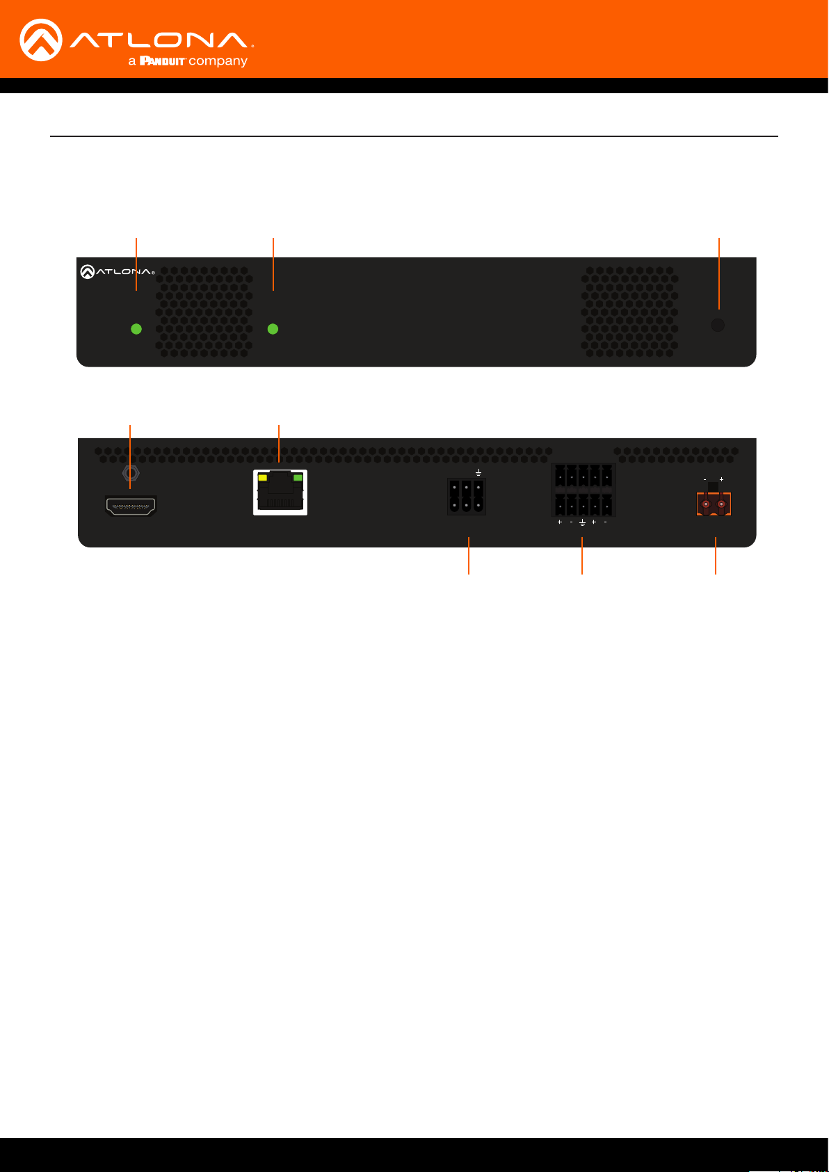
Panel Description
TM
OMNISTREAM
LINKPWR
AT-OMNI-121
OMNISTREAM
Front
4 5
HDMI OUT
AT-OMNI-121
Rear
1 2
LINKPWR
TM
ETHERNET
TX
RX
1
RS-232
IN
OUT
6 87
AUDIO
L
3
R
DC 48V
1 PWR
This LED indicator is green when the unit is
powered.
2 LINK
These LED indicators show the active input
status.
3 REBOOT
Use a pointed object to press this recessed
button and reboot the unit.
4 HDMI OUT
Connect an HDMI cable from this port to an HD
display.
5 ETHERNET
Connect an Ethernet cable from this port to the
Local Area Network (LAN).
6 RS-232
Use the included Phoenix terminal block to
connect an RS-232 device to this port.
The bottom three pins support IR pass-through.
Refer to IR Connections (page 14) for more
information.
7 AUDIO
Connect the included Phoenix terminal blocks
to embed audio on the output stream and/or
connect to an audio output device.
8 DC 48V
Connect the optional 48V DC power supply to
this power receptacle. This power supply is
available, separately.
AT-OMNI-121 / AT-OMNI-122
10

AT-OMNI-122
1 2
ID
PWR
LINK
TM
O
MNISTREAM
Panel Description
O
MNISTREAM
Front
AT-OMNI-122
Rear
1 2 3
PWR
1
TM
5
HDMI OUT
2
LINK
1 2
1
6
ETHERNET
4
ID
1
L
R
TX
RX
1
2
2
RS-232
IN
OUT
AUDIO
7 9
2
L
R
DC 48V
8
1 PWR
This LED indicator is green when the unit is
powered.
2 LINK 1 / LINK 2
These LED indicators will be green when the link
integrity between the between the encoder and
the switch is good.
3 ID
Press this button to send out a broadcast
message to any network devices that are
listening. This button is also used to set the
decoder to factory-default settings. Refer to ID
Button (page 24) for more information.
4 REBOOT
Use a pointed object to press this recessed
button and reboot the unit.
5 HDMI OUT 1 / HDMI OUT 2
Connect HDMI cables from these ports to an HD
display.
6 ETHERNET 1 / ETHERNET 2
Connect Ethernet cables from these ports to the
Local Area Network (LAN).
7 RS-232
Use the included Phoenix terminal block to
connect up to two RS-232 devices to this port.
The RS-232 2 port also supports IR passthrough. Refer to IR Connections (page 14) for
more information.
8 AUDIO 1 / AUDIO 2
Connect the included Phoenix terminal blocks
to embed audio on the output stream and/or
connect to an audio output device.
9 DC 48V
Connect the optional 48V DC power supply
to this power receptacle. This power supply
is available, separately, and is required when
connecting the encoder to non-PoE compatible
switch or when embedding and de-embedding of
analog audio.
AT-OMNI-121 / AT-OMNI-122
11
Installation
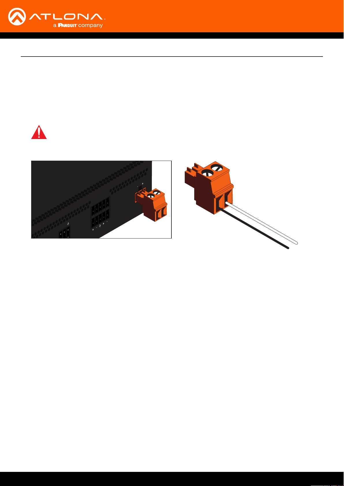
External Power (Optional)
OmniStream decoders are powered by PoE (Power over Ethernet), when connected to a PoE-capable switch. If a
PoE-switch is not used, then the optional 48 V power supply (Atlona part no. AT-PS-48083-C) can be purchased,
separately. Insert the positive and negative leads, from the power supply, into the terminals of the 2-pin captive
screw connector block, as shown. The orange 2-pin captive screw connector block is included with the OmniStream
power supply package.
IMPORTANT: The external power supply must be connected to the decoder when embedding and
de-embedding audio using the AUDIO IN and/or AUDIO OUT ports.
R
AUDIO
L
IN
DC 48V
White
TX
RX
OUT
1
Black
NEG
POS
AT-OMNI-121 / AT-OMNI-122
12
Installation
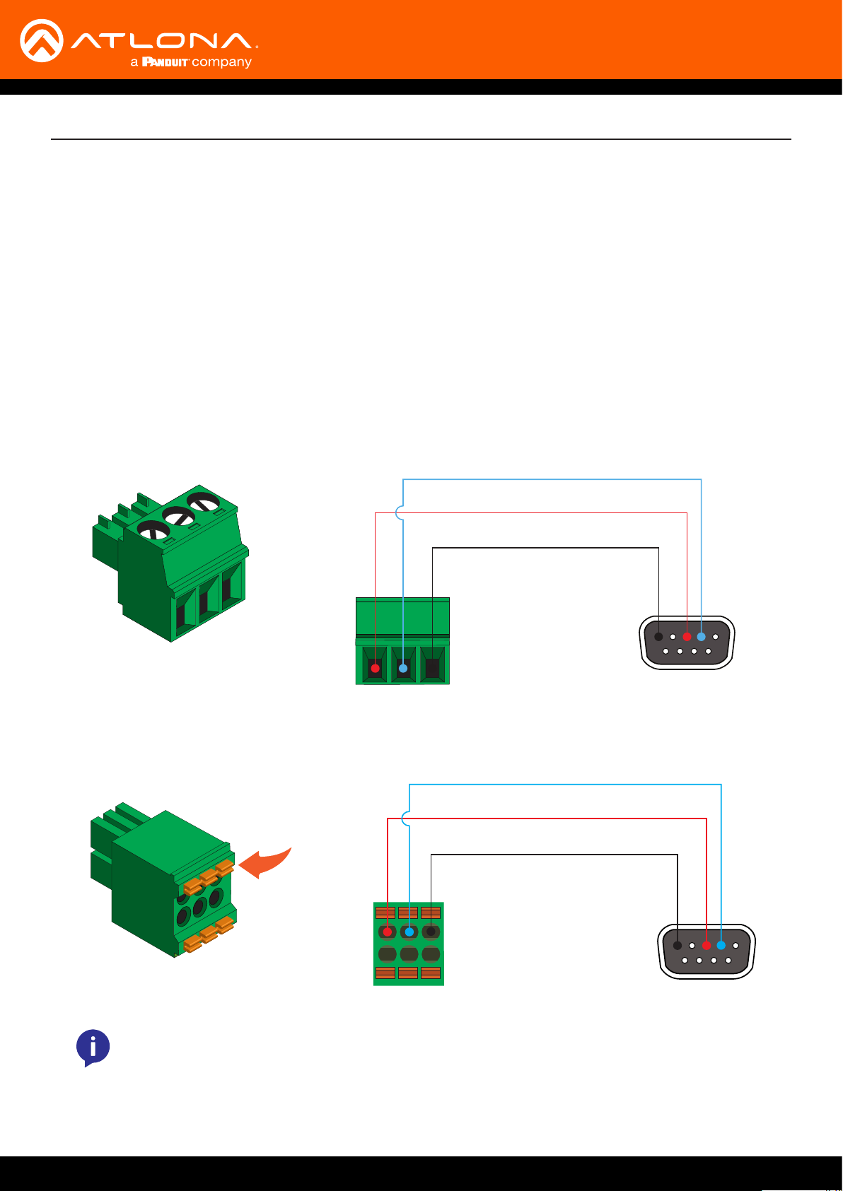
RS-232 Connections
Both the AT-OMNI-121 and AT-OMNI-122 provide RS-232 over IP, allowing communication between an automation
system and an RS-232 device. This step is optional. Note that dierent Phoenix connectors are provided with each
product.
1. Use wire strippers to remove a portion of the cable jacket.
2. Remove at least 3/16” (5 mm) from the insulation of the RX, TX, and GND wires.
3. Insert the TX, RX, and GND wires into correct terminal on the included Phoenix block. If using non-tinned
stranded wire, press the orange tab, above the terminal, while inserting the exposed wire. Repeat this step for
the TX, RX, and GND connections.
AT-OMNI-121
TX
RX
GND
AT-OMNI-122
TX
Push tab
to unlock
NOTE: Typical DB9 connectors use pin 2 for TX, pin 3 for RX, and pin 5 for ground. On some
devices, pins 2 and 3 are reversed.
RX
GND
AT-OMNI-121 / AT-OMNI-122
13
SIGNAL (white/black)
Installation
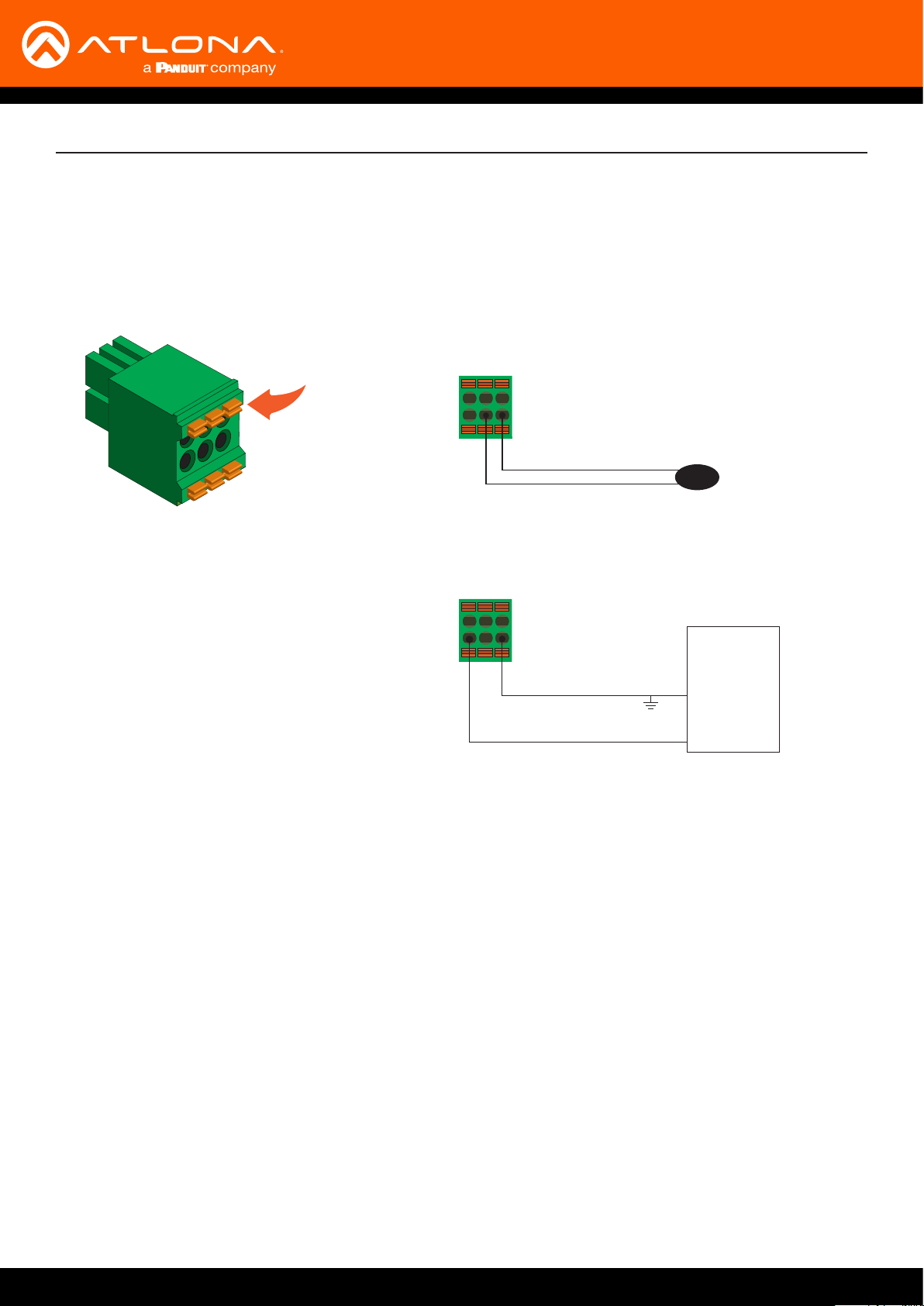
IR Connections
The same port that provides RS-232 connections also supports bidirectional IR pass-through, allowing a device to
be controlled from either the headend or the decoder endpoint. This step is optional. Either the top three or bottom
three set of terminals can be used for IR. Only the RS-232 2 port (bottom set of connectors) supports both RS-232
and IR. Therefore, this port must be used for IR connections. Refer to IR Control (page 36) for more information.
Push tab
to unlock
IR emitter conguration
RX TX GND
GND (black)
IR extender conguration
RX TX GND
GND (black)
SIGNAL (white/black)
IR emitter
Control
Unit
GND
TX out
AT-OMNI-121 / AT-OMNI-122
14
Installation
Side View Side View
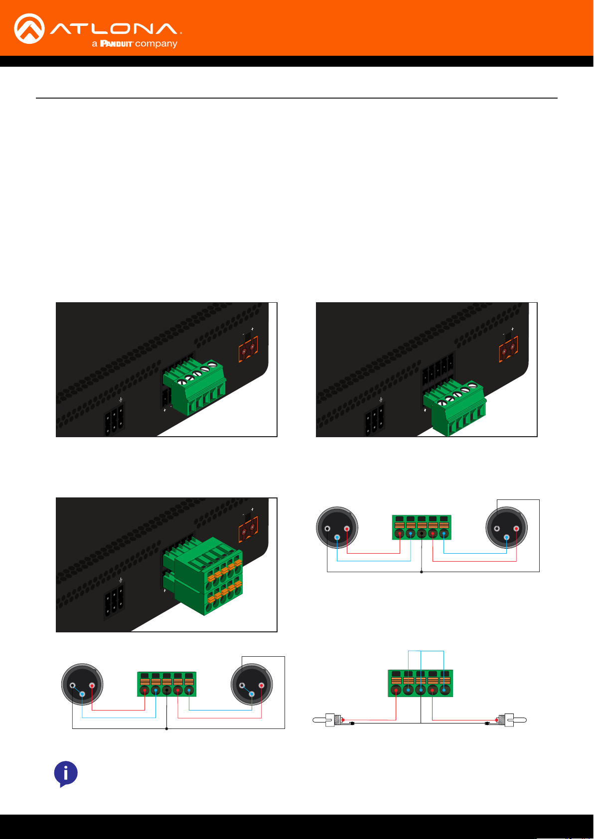
Audio Connectors
In addition to passing audio directly from the encoder to the decoder, both the AT-OMNI-121 and AT-OMNI-122
provide two additional audio options. Either option can be used or they can be used simultaneously.
• HDMI audio can be de-embedded and output to two-channel analog audio.
• Two-channel analog audio can be embedded and output over HDMI.
Use the included dual ve-pin Phoenix blocks. Note that each product comes with dierent connector blocks.
This step is optional. Refer to Conguring Audio Output (page 51) for more information.
AT-OMNI-121
• If either the AUDIO IN or AUDIO OUT port will be used, then connect the included 5-pin “captive screw” Phoenix
blocks, as shown below.
R
AUDIO
L
IN
TX
RX
OUT
1
DC 48V
IN
TX
RX
OUT
1
AUDIO
L
R
DC 48V
2-channel analog audio input (top) 2-channel analog audio output (bottom)
• If both AUDIO IN and AUDIO OUT terminals will be used, then connect the included 5-pin “push spring” Phoenix
blocks, as shown below.
TX
RX
RS-232
1 2
R
AUDIO
L
IN
OUT
1
DC 48V
3
+
-
GND GND
Balanced XLR audio
-
+
1 2
3
1 2
3
+
-
GND GND
NOTE: Unblanaced XLR audio pins require Pin 1 and Pin 3 to be connected.
AT-OMNI-121 / AT-OMNI-122
-
-
1 2
3
-
+
GND
+
+
GND
Unbalanced RCA audioUnbalanced XLR audio
15
Installation
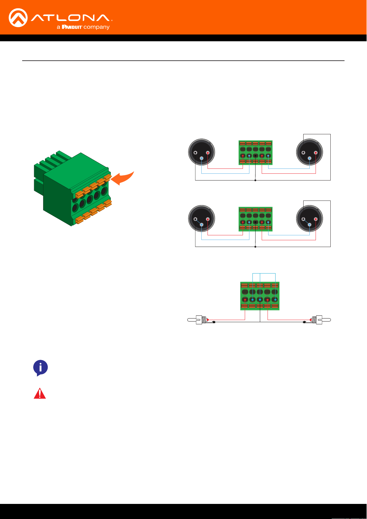
AT-OMNI-122
Use the top 5 pins to connect audio input sources. Use the bottom ve pins to connect to audio output devices.
1. Use wire strippers to remove a portion of the cable jacket.
2. Locate the included Phoenix block connectors. Press the orange tab, above the terminal, while inserting the
exposed wire. Release the orange tab to lock the wire in place. Balanced or unbalanced audio can be used.
Push tab
to unlock
1 2
3
+
-
GND GND
-
+
1 2
3
Balanced XLR audio
1 2
3
+
-
GND GND
-
+
1 2
3
Unbalanced XLR audio
-
-
+
Side View Side View
GND
+
GND
Unbalanced RCA audio
NOTE: Unblanaced XLR audio pins require Pin 1 and Pin 3 to be connected.
IMPORTANT: When using analog audio inputs on the OmniStream decoder, the decoder must be
powered using the 48V power supply (AT-PS-48083-C). This power supply is sold separately and
can be purchased from Atlona.
AT-OMNI-121 / AT-OMNI-122
16

Installation
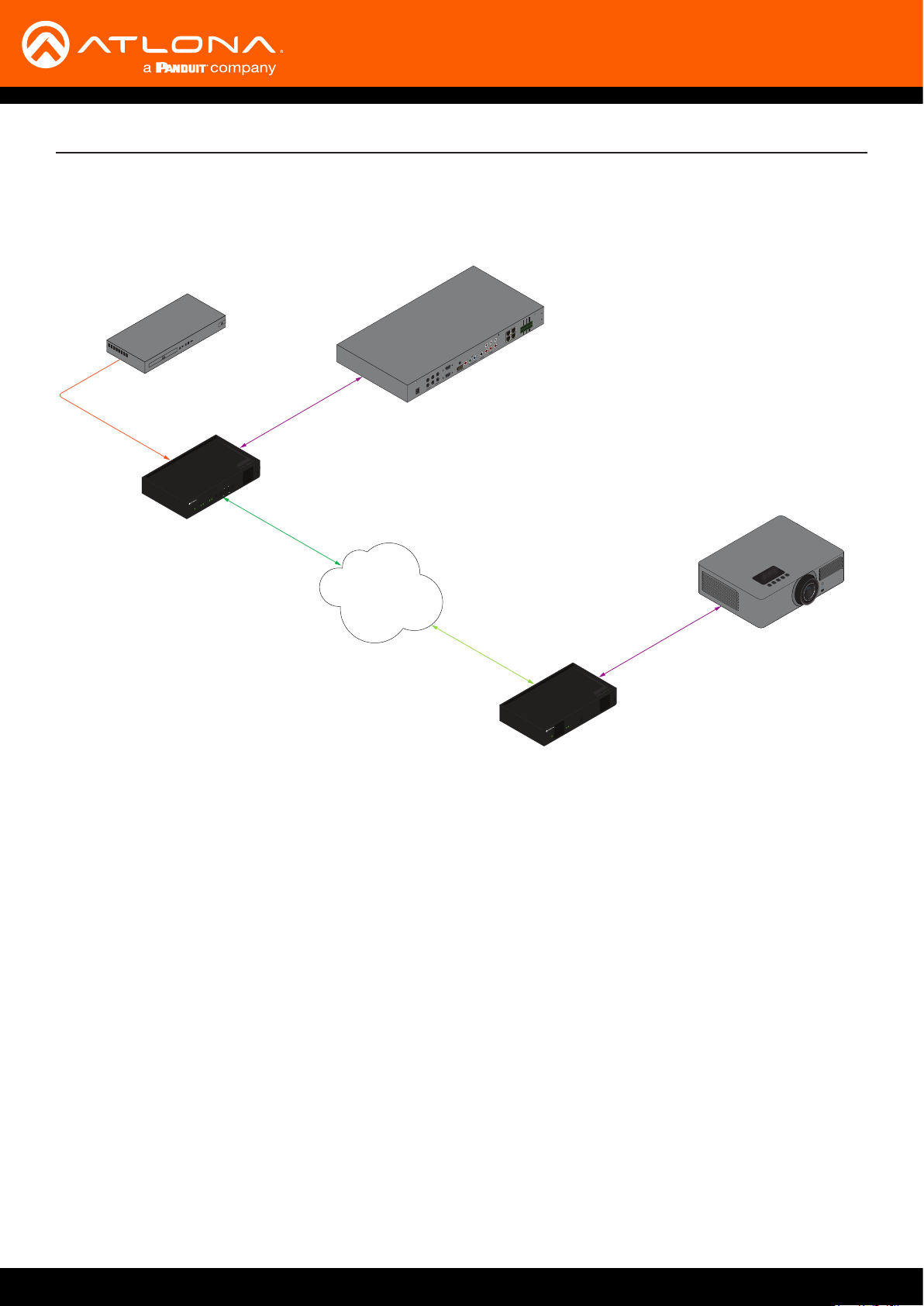
Connection Instructions
1. Connect an Ethernet cable from the ETHERNET port on the decoder to a PoE-capable switch on the Local Area
Network (LAN). If using the dual-channel decoder, connect a separate Ethernet cables to ETHERNET 1 and
ETHERNET 2 ports.
2. Connect an HDMI cable from the HDMI OUT port on the decoder to a display. If using the dual-channel
decoder, connect an HDMI cable from each HDMI OUT port to a display.
3. RS-232 (optional)
• Connect the RS-232 controller/automation system to the RS-232 port on the decoder.
• Connect the RS-232 device to the RS-232 port on the decoder.
4. External Audio (optional)
• Connect the audio inputs to the decoder, as required.
IMPORTANT: If a PoE-capable switch is not available, then the 48V DC power supply (sold
separately) must be connected to the decoder.
• Connect the audio outputs to the decoder, as required.
IMPORTANT: When using analog audio inputs on the OmniStream decoder, the decoder must be
powered using the 48V power supply (AT-PS-48083-C). This power supply is sold separately and
can be purchased from Atlona.
5. IR (optional)
NOTE: For dual-channel decoders, only the RS-232 2 port supports both serial and IR. Single-
channel decoders only support IR on the RS-232 2 port. The IR emitter or IR receiver must always
be connected to this port. Refer to IR Control (page 36) for more information.
• IR emitter
Connect the IR emitter to the TX and GND pins of the RS-232 2 port. The IR emitter must be placed no
more than 1” from the IR sensor on the device, in order to function properly.
• IR extender
Connect the IR extender from the RX and GND pins of the RS-232 2 port to the associated pins on the
control system.
6. Once power is applied, the PWR indicator, on the front panel, will turn red, then amber, then green.
AT-OMNI-121 / AT-OMNI-122
17
AT-OMNI-112
Blu-ray Player
INPUT
DISPLAY
LINK
HDMI
1 2 1 2
PWR
TM
TREAM
S
MNI
O
VOLUME
ID
RS-232 Control
Ethernet
Connection Diagram
NO
COM
NC
2 3 4
NO
COM
NC
1
NO
COM
NC
NO
COM
NC
GND
+12V
SIG
GND
+12V
SIG
GND
+12V
SIG
GND
+12V
SIG
ETHERNET
L
DIGITAL
R
COAX OUT
COMPONENT
AUDIO OUT AUDIO IN
HDMI
VIDEO OUT
SERIAL 1
5
LAN
3
6
1
4
FACTORY
2
RESET
IR OUT
48V DC
SERIAL 2
2
Automation
Control System
Installation
Ethernet / PoE
AT-OMNI-122
Projector
RS-232 Control
ID
LINK
1 2
PWR
TM
TREAM
S
MNI
O
AT-OMNI-121 / AT-OMNI-122
18
Conguration
Discovery using AMS
It is recommended that the Atlona Management System (AMS) be used to congure and control OmniStream
devices. AMS uses multicast Domain Name Server (mDNS) to automatically congure each decoder on the network.
AMS is free and can be downloaded from https://www.atlona.com/ams.
By default, the decoders are set to DHCP mode, allowing a DHCP server (if present) to assign the decoder an IP
address. Once an IP address has been assigned, the Atlona Management System (AMS) can be used to manage the
product on the network. Note that AMS will only be able to discover decoders if they are on the same VLAN.
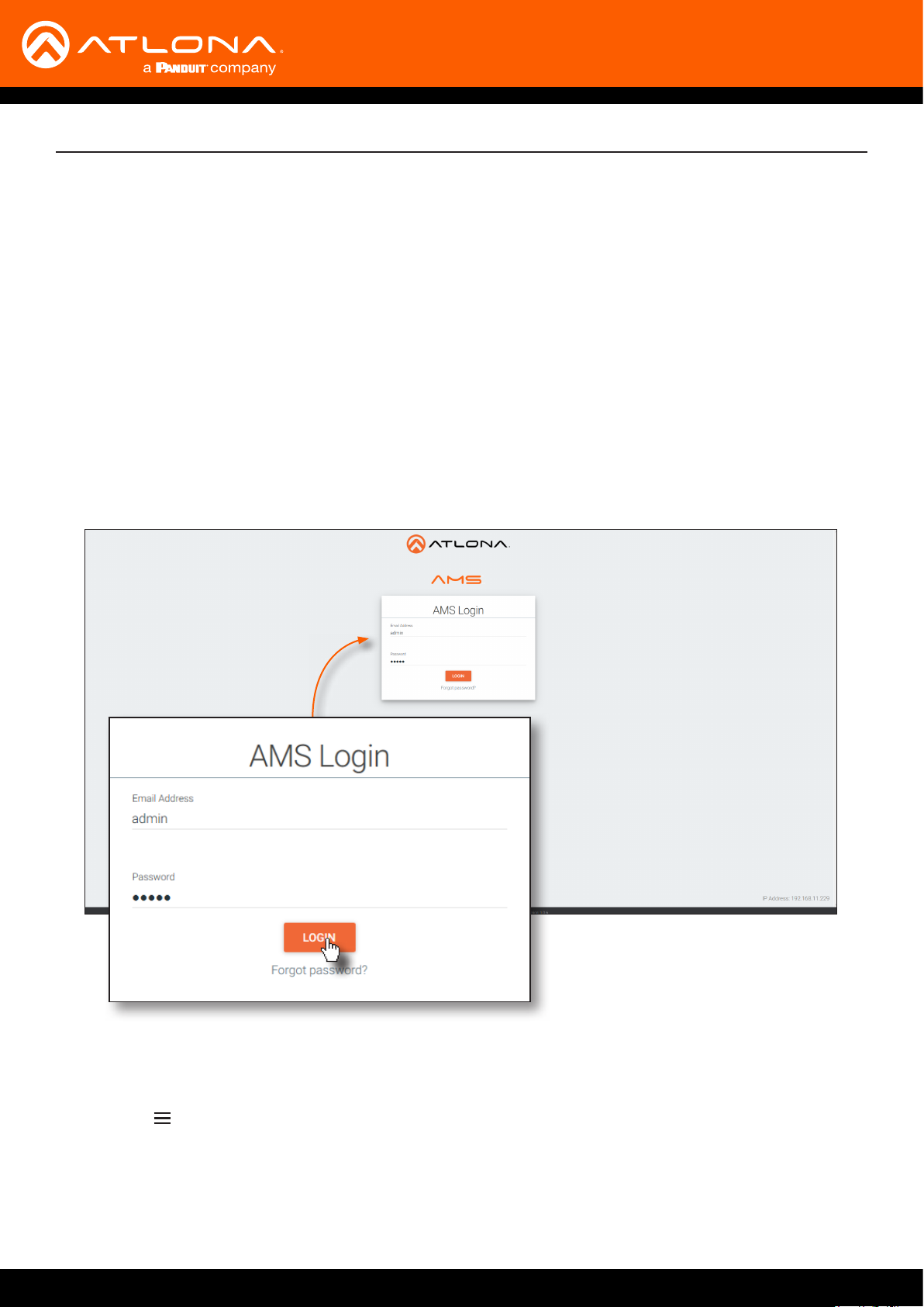
Accessing Decoders in AMS
1. Launch a web browser and enter the IP address of AMS, in the address bar.
2. Enter the required login credentials.
3. Click the Login button.
4. The AMS Dashboard will be displayed.
5. Click the icon, in the upper-left corner of the AMS Dashboard.
AT-OMNI-121 / AT-OMNI-122
19

Conguration
6. Click Devices from the y-out menu.
7. Click the Unassigned option.
All available decoders will be displayed under the Unassigned category. When a decoder is unassigned, it
means that it has not been assigned to a site, building, and/or room. Refer to the AMS User Manual for more
information on these topics.
If a DHCP server is not found within 60 seconds, the decoder will be placed in Auto IP mode and assigned an
IP address within the range of 169.254.xxx.xxx. If this occurs, congure the network interface of the computer
that is running AMS, located on the same subnet (169.254.xxx.xxx, subnet mask 255.255.0.0). Refer to the User
Manual for more information on conguring a decoder in Auto IP mode.
If no OmniStream decoders are found, then verify the following:
• The computer that is running AMS must be on the same network as the OmniStream device.
• Remove any network restrictions that may be in place. In order for mDNS to function properly, there must
not be restrictions applied to the network.
AT-OMNI-121 / AT-OMNI-122
20
Conguration
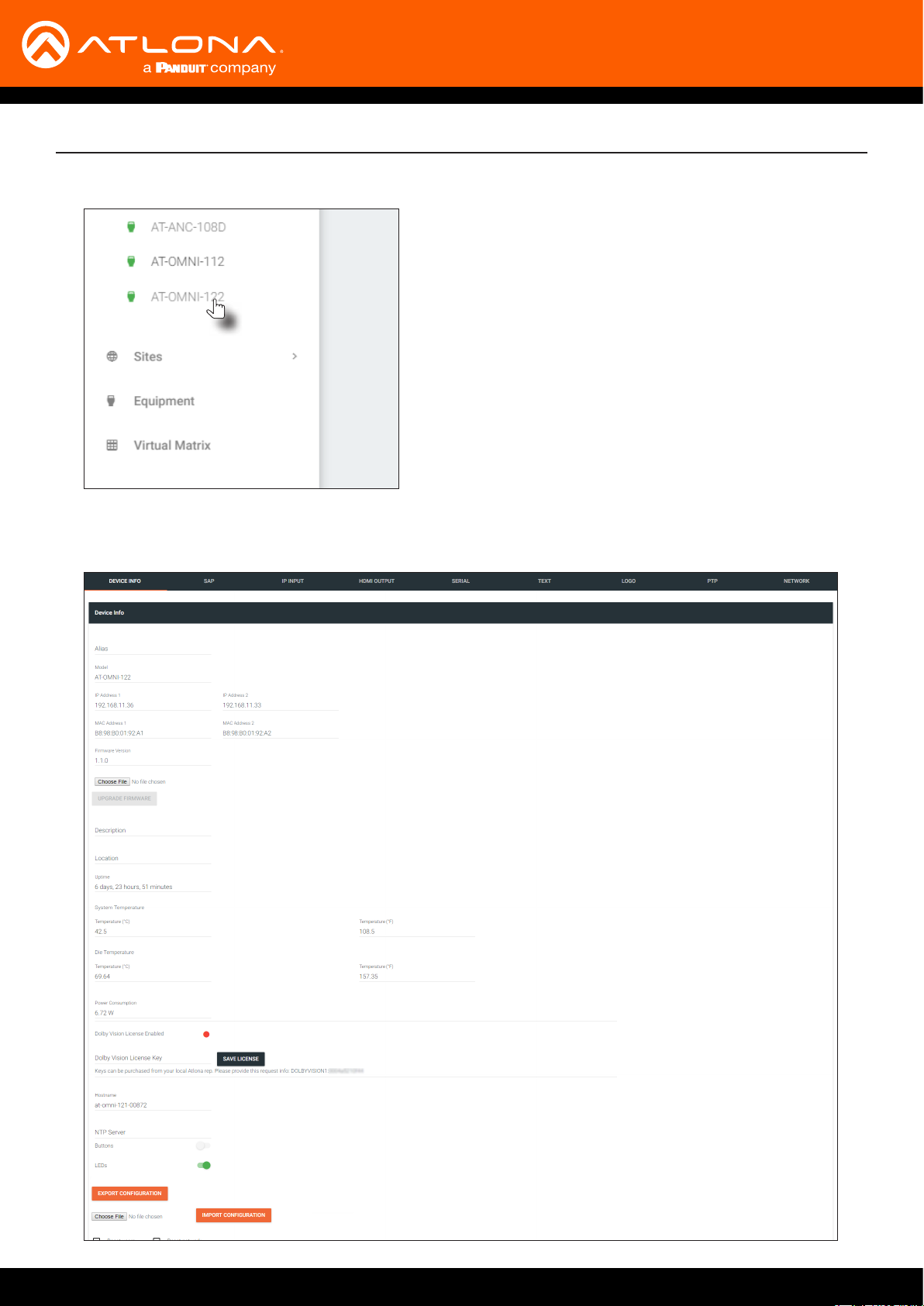
8. Click the desired decoder from the Unassigned device list.
Once the unit is selected, the control interface for the decoder will be displayed. The illustration below shows the
DEVICE INFO screen for an AT-OMNI-122 decoder.
AT-OMNI-121 / AT-OMNI-122
21
Conguration
Conguring a Static IP Address
The following section is only required to set the decoder, currently in Auto IP mode, to a static IP address. If a DHCP
server is not found within 60 seconds, decoders are automatically placed in Auto IP mode and will be assigned an IP
address within the range 169.254.xxx.xxx. If this occurs, a static IP address can be assigned to the decoder in order
for AMS to locate it on the network.
1. Make sure that the decoder is powered. Power will need to be supplied either by the external 48V power supply
(not included) or by connecting an Ethernet cable from the decoder to a PoE-capable switch. If using the
AT-OMNI-122, the Ethernet cable can be connected to either ETHERNET 1 or ETHERNET 2.
2. Connect an Ethernet cable from the PC, directly to one of the Ethernet ports on the decoder. Make sure that the
computer being used has AMS installed.
3. Congure the PC to a static IP address that is on the same subnet as the decoder.
4. Login to AMS. Refer to Accessing Decoders in AMS (page 19) if necessary.
IMPORTANT: Before continuing, write down the current IP settings in order to restore them, later.
If Obtain an IP address automatically and Obtain DNS server automatically are selected, then this
step is not required.
5. Locate the decoder under the Unassigned section within AMS.
6. Click on the device.
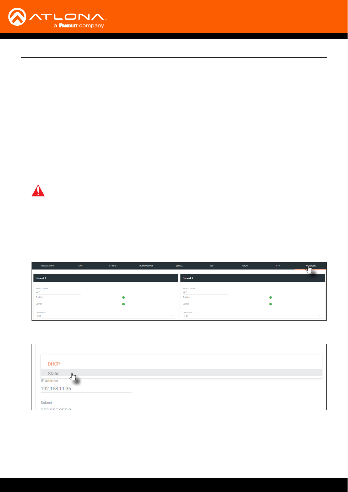
7. Under AMS, click the NETWORK tab.
8. Click the DHCP Mode drop-down list and select Static.
9. Enter the required network information for the decoder in the IP Address, Subnet, and Gateway elds.
10. Click the Save button in the bottom-right corner, to apply the changes.
11. Disconnect the decoder from the PC and connect it to the network.
12. The decoder is now ready for use.
AT-OMNI-121 / AT-OMNI-122
22

Basic Operation
LED Indicators
The following table provides a listing of front-panel LED indicators and their status:
LED Description
PWR Off • If using a PoE switch, make sure that the port on the switch that is
connected to the decoder, has PoE enabled. When the decoder is
powered using PoE, the PWR indicator will be green.
• Check the Ethernet cable for possible damage or loose connections.
• Connect the optional 48V DC power supply (available from atlona.
com) to the decoder. When using an external power supply, the PWR
indicator will be red.
Red • The decoder is booting.
Green • The decoder is ready.
LINK 1 / 2 Red • The optional 48V DC power supply is connected, but no Ethernet
cables are connected between the switch and the ETHERNET port(s).
• Check the Ethernet cable for possible damage or loose connections.
Green • Link integrity is good between the decoder and the network.
AT-OMNI-121 / AT-OMNI-122
23
Basic Operation
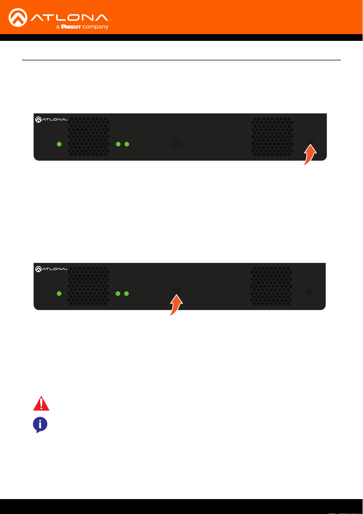
Rebooting OmniStream
To reboot the OmniStream decoder, press and release the recessed button, on the far-right side of the unit, using a
small, pointed object. Rebooting the decoder does not reset the decoder to factory-default settings.
ID
O
MNISTREAM
PWR
LINK
1 2
TM
ID Button
This feature is not available on the single-channel OmniStream decoder (AT-OMNI-121).
The ID button serves two functions:
1. Sends a broadcast message, over the network, to any devices that may be listening.
2. Resets the decoder to factory-default settings.
ID
O
MNISTREAM
PWR
LINK
1 2
TM
Broadcast Messaging
Press and release the ID button to send a broadcast notication over the network to any devices that may be
listening.
Factory-Reset using the Front Panel
WARNING: Performing a factory-default reset will erase all user-programmed settings from the
decoder. IP settings are not preserved.
NOTE: If using AT-OMNI-121 decoders, the factory-reset procedure must be performed using RS232 or IP. Refer to Connecting RS-232 to OmniStream (page 53) for more information.
1. Press and hold the ID button for approximately 30 seconds.
2. The LED indicators on the front panel will ash, then turn “o.”
3. The decoder is now reset and will need to be recongured.
AT-OMNI-121 / AT-OMNI-122
24
Basic Operation
Factory-Reset using RS-232
1. Connect a USB to RS-232 cable from the computer to the OmniStream decoder. Refer to Connecting RS-232 to
OmniStream (page 53) for information on preparing a cable and connecting to OmniStream units.
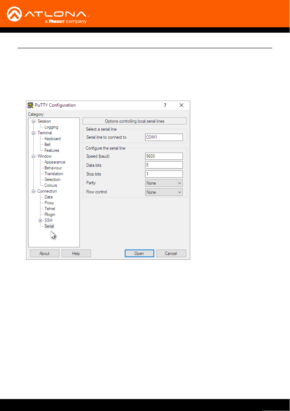
2. Launch a terminal program that supports RS-232, such as PuTTY. PuTTY is a free and open-source terminal
emulator and can be downloaded from https://www.putty.org. The following example uses PuTTY.
3. Click Serial, near the bottom on the left-hand side pane.
4. Enter the COM port in the Serial line to connect to eld. This is the COM port used by the computer, to
communicate with the OmniStream decoder. Refer to Connecting RS-232 to OmniStream (page 53) for more
information on obtaining the proper COM port.
5. Enter the baud rate, data bits, and stop bits as follows: 9600, 8, 1.
6. Click the Parity drop-down list and select None. Click the Flow control drop-down list and select None.
7. Click Open to establish the RS-232 connection.
8. Enter the login credentials. The default login credentials are listed below. Note that login information is case-
sensitive.
username: admin
password: Atlona
9. Once connected, the CLI (Command Line Interface) will be displayed. Execute the following command and press
[ENTER]:
Mreset
AT-OMNI-121 / AT-OMNI-122
25
Basic Operation
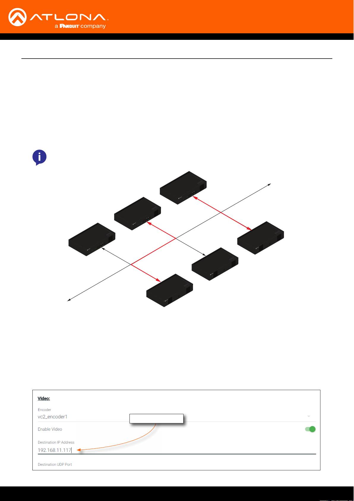
Unicast Mode
The term unicast is used to describe a conguration where information is sent from an encoder to a single decoder.
Although it is common to have multiple encoder and decoder units within a system, it may also be desirable to
restrict a single encoder to communicate with one decoder. In unicast mode, OmniStream encoders and decoders
function similar to an n x 1 switcher. Changing the destination IP address at the encoder, will direct the stream to be
received by a dierent decoder.
The illustration below shows three encoders and three decoders on a network, operating in unicast mode. The red
lines indicate the data paths from each encoder to a separate (single) decoder.
NOTE: By default, both encoders and decoders are shipped in multicast mode.
192.168.11.115
192.168.11.114
Encoder
LINK
HDMI
1 2 1 2
PWR
TM
TREAM
S
MNI
O
INPUT
DISPLAY
192.168.11.116
ID
VOLUME
Encoder
LINK
HDMI
1 2 1 2
PWR
TM
TREAM
S
MNI
O
Encoder
ID
INPUT
DISPLAY
VOLUME
Decoder
LINK
1 2
PWR
TM
TREAM
S
MNI
O
INPUT
DISPLAY
VOLUME
LINK
HDMI
1 2 1 2
PWR
TM
TREAM
S
MNI
O
LAN
ID
192.168.11.117
ID
Decoder
ID
LINK
1 2
PWR
TM
TREAM
S
MNI
O
192.168.11.121
Decoder
ID
LINK
1 2
PWR
TM
TREAM
192.168.11.118
S
MNI
O
1. Login to AMS. Refer to Accessing Decoders in AMS (page 19) if necessary.
2. Go to the encoder AMS interface. Refer to the OmniStream Single-Channel / Dual Channel A/V Encoder User
Manual, if necessary.
3. Click SESSION in the menu bar and scroll down to the Video section.
4. Enter the IP address of the decoder in the Destination IP Address eld. If using dual-channel encoders,
repeat this process for each session.
IP address of decoder
AT-OMNI-121 / AT-OMNI-122
26
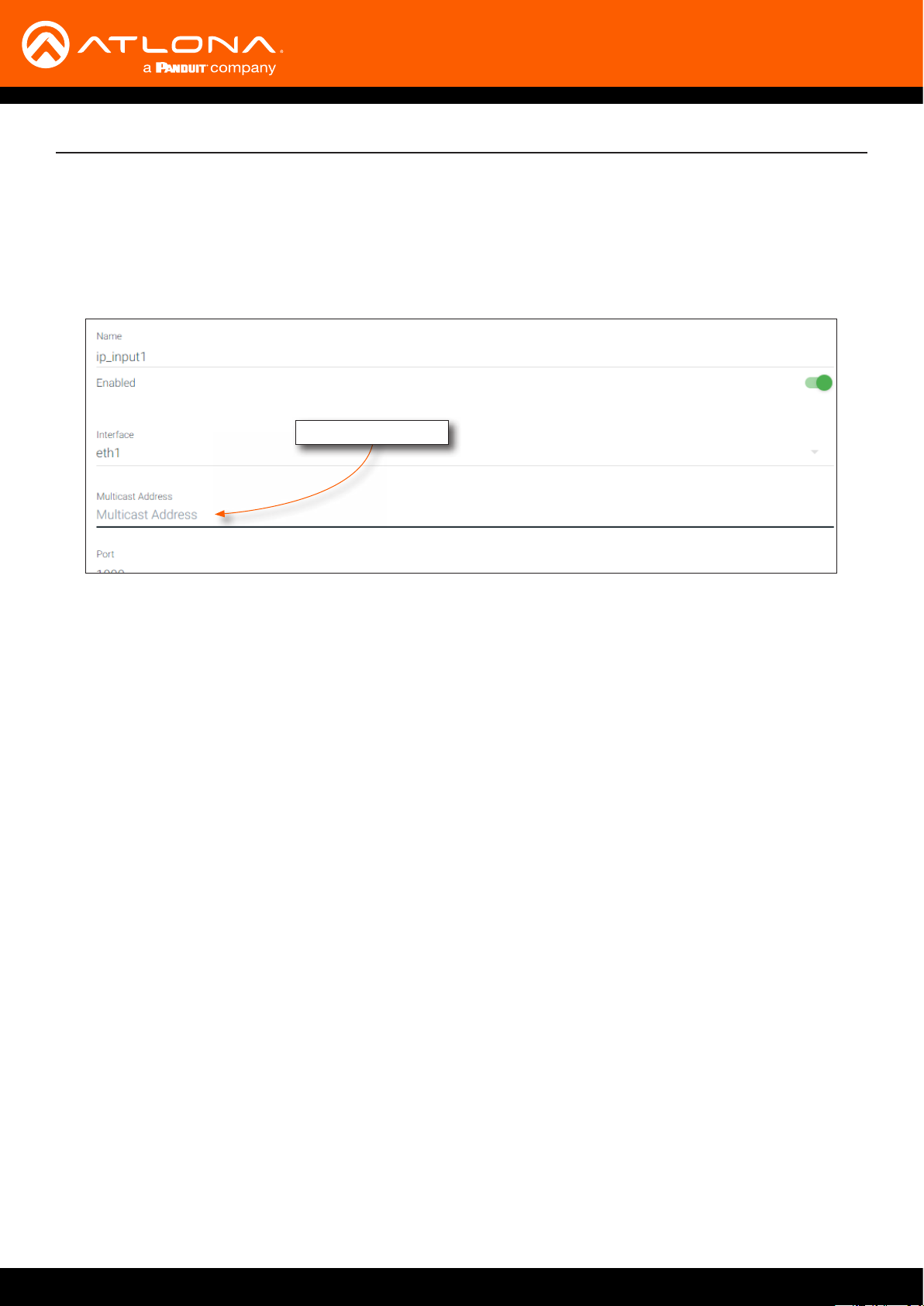
5. Go to the decoder AMS interface.
6. Click IP INPUT from the menu.
7. Remove the IP address from the Multicast Address eld.
8. Click the SAVE button to commit changes.
Field should be blank
Basic Operation
9. Unicast setup is complete. The decoder unit will now receive streams exclusively from the encoder containing
the IP address of this decoder.
AT-OMNI-121 / AT-OMNI-122
27
Basic Operation
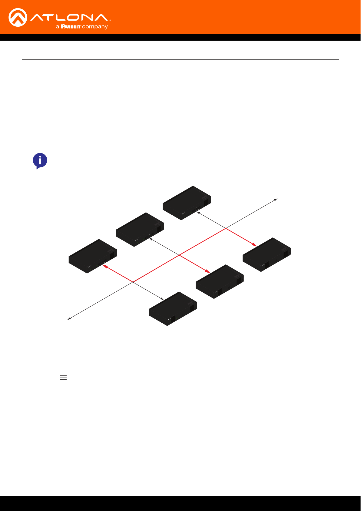
Multicast Mode
The term multicast is used to describe a conguration where information is sent from one or more points to a set of
other points. For example, a single encoder can transmit data to multiple decoders. In addition, if multiple encoders
are used, each encoder can stream data to any decoder that is not already receiving data from an encoder.
In multicast mode, OmniStream encoders and decoders function similar to a matrix switcher.
The illustration below shows three encoders and three decoders on a network, operating in multicast mode, where
multiple decoders are subscribed to a single encoder. The red lines indicate the data paths from an encoder
(192.168.11.117) to multiple decoders.
NOTE: By default, both encoders and decoders are shipped in multicast mode.
192.168.11.115
192.168.11.114
Encoder
LINK
HDMI
1 2 1 2
PWR
TM
TREAM
S
MNI
O
INPUT
DISPLAY
VOLUME
192.168.11.116
ID
Encoder
LINK
HDMI
1 2 1 2
PWR
TM
TREAM
S
MNI
O
Encoder
ID
INPUT
DISPLAY
VOLUME
Decoder
LINK
1 2
PWR
TM
TREAM
S
MNI
O
INPUT
DISPLAY
VOLUME
LINK
HDMI
1 2 1 2
PWR
TM
TREAM
S
MNI
O
LAN
ID
192.168.11.117
ID
Decoder
ID
LINK
1 2
PWR
TM
TREAM
192.168.11.118
S
MNI
O
1. Login to AMS. Refer to Accessing Decoders in AMS (page 19) if necessary.
2. The AMS Dashboard will be displayed.
3. Click the icon, in the upper-left corner of the AMS Dashboard.
Decoder
LINK
1 2
PWR
TM
TREAM
S
MNI
O
ID
192.168.11.121
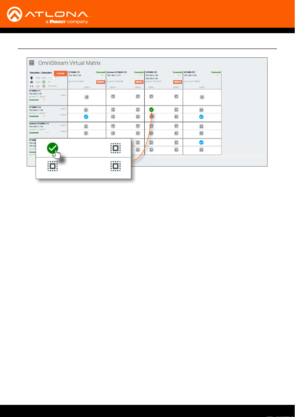
4. Click Virtual Matrix from the y-out menu. Refer to The Virtual Matrix (page 122), if necessary.
5. Locate the desired encoder in the Virtual Matrix, as shown on the next page.
6. Create a cross-connection to the desired decoder. When a cross-connection is created, AMS will automatically
assign a multicast IP address to both the encoder and decoder. By default, AMS automatically assigns a
multicast IP address to each OmniStream encoder and decoder.
Refer to the illustration on the following page, if necessary.
AT-OMNI-121 / AT-OMNI-122
28
Basic Operation
AT-OMNI-121 / AT-OMNI-122
29

Basic Operation
Setting the Video Mode
OmniStream oers two video modes: Video and PC application. These two modes will optimize the image, based
on the type of information that is being displayed. Use the Video mode when display motion graphics/video. Set
this mode to PC application when viewing static images, such as spreadsheets or similar content.
1. Login to AMS. Refer to Accessing Decoders in AMS (page 19), if necessary.
2. Click the HDMI OUTPUT in the menu bar.
3. Scroll down to the Video Optimization section and click the Video Optimization drop-down list to select the
desired mode.
Mode Description
Computer Graphics Optimizes the image when viewing static images, such as
spreadsheets or similar content.
Motion Video Provides the best viewing experience when streaming motion graphics
and/or video.
4. Click the SAVE button, within the Video Optimization section to commit changes. Note that switching between
video modes may take a few moments to complete.
5. Go to the encoder interface and repeat the process. Refer to the OmniStream Single-Channel / Dual Channel
A/V Encoder User Manual, if necessary.
NOTE: In order to use 3840x2160p60 signals, the System mode must be set to Video.
AT-OMNI-121 / AT-OMNI-122
30
 Loading...