

Atlona OmniStream 112 Installation Manual
1
Installation Guide
AT-OMNI-112
OmniStream 112 Dual-Channel Networked AV Encoder
AT-OMNI-112
The Atlona OmniStream™ 112 (AT-OMNI-112) is a networked AV encoder with two independent
channels of encoding for two HDMI sources up to 4K/UHD, plus embedded audio and RS-232
control. OmniStream is designed for distributing AV over 1 Gigabit Ethernet in enterprises and
other large-scale installations. The OmniStream 112 features SMPTE VC-2 visually lossless
compression for critical-quality video applications, with extremely low, sub-frame latency from
encode to decode. It also includes selectable AES-128 encryption, and SMPTE 2022-5 forward
error correction for robust AV distribution spanning multiple networks. This dual-channel encoder
is housed in a half-width rack enclosure and is ideal for high-density rack installations. With two
Ethernet ports, the OmniStream 112 can also deliver duplicate AV streams to two networks for
full system redundancy in mission-critical applications.
IMPORTANT: Visit http://www.atlona.com/product/AT-OMNI-112 for the latest rmware
updates and User Manual.
1 x AT-OMNI-112
1 x Phoenix terminal block, 6-pin (push spring)
1 x Wall/table mounting brackets
4 x Rubber feet
1 x Installation Guide
• OmniStream requires the Atlona Management System (AMS) which provides discovery,
management, and conguration assistance. AMS is a free application that can be
downloaded from the Atlona web site at http://atlona.com/product/at-sw-ams/
• OmniStream uses mDNS as the discovery mechanism. In order for mDNS to function
properly, there must not be restrictions applied to the network. VPN can be used to
connect to a computer that is running AMS, on the same network. However, VPN cannot
be used when AMS is running on the local machine.
Package Contents
Operating Notes

2
Installation Guide
AT-OMNI-112
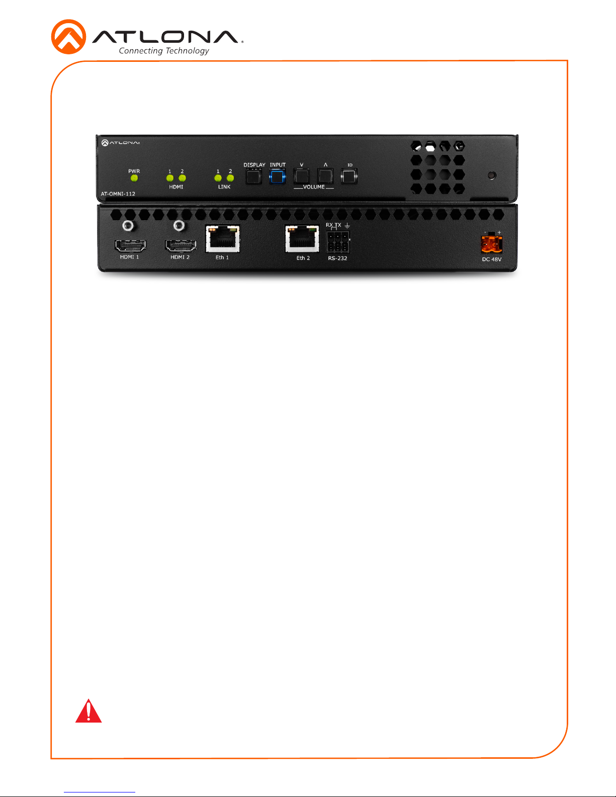
1 2 1 2
HDMI
PWR
LINK
VOLUME
DISPLAY
INPUT
ID
AT-OMNI-112
DC 48V
Eth 1 Eth 2
HDMI 1 HDMI 2
+
RS-232
RX
TX
1
2
1 2 1 2
HDMI
PWR
LINK
VOLUME
DISPLAY
INPUT
ID
AT-OMNI-112
1 PWR
This LED indicator is green when the unit
is powered.
2 HDMI 1 / HDMI 2
These LED indicators show the active
input status.
3 LINK 1 / LINK 2
These LED indicators show the link status
of the encoder.
4 DISPLAY
Press this button to toggle the power state
of the desired display.
5 INPUT
Press this button to switch between HDMI
1 and HDMI 2 inputs.
6 VOLUME
Press these buttons to adjust the output
volume of the desired display.
7 ID
Press this button to identify the unit within
the AMS software.
8 REBOOT
Use a pointed object to press this
recessed button and reboot the unit.
9 HDMI 1 / HDMI 2
Connect HDMI cables from these ports to
an HD source.
10 Eth 1 / Eth 2
Connect Ethernet cables from these ports
to the Local Area Network (LAN).
11 RS-232
Use the included Phoenix terminal block
to connect up to two RS-232 controllers
or automation systems.
12 DC 48V
Connect the optional 48V DC power
supply to this power receptacle. This
power supply is available, separately.
Panel Descriptions
1 2
3
4 5 6 7 8
11109 12
3
Installation Guide
AT-OMNI-112
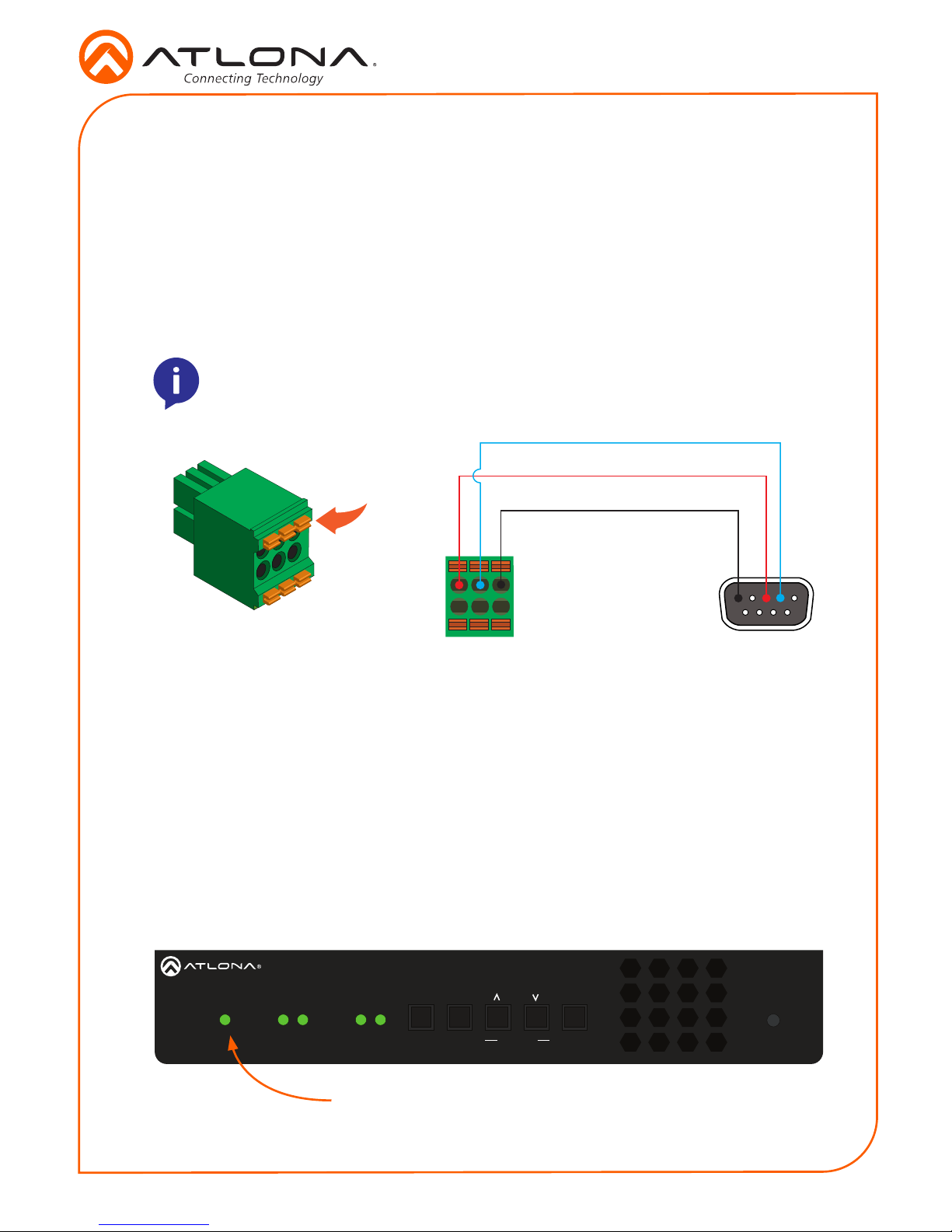
The AT-OMNI-112 provides RS-232 over IP which allows communication between an automation
system and an RS-232 device. This step is optional.
1. Use wire strippers to remove a portion of the cable jacket.
2. Remove at least 3/16” (5 mm) from the insulation of the RX, TX, and GND wires.
3. Insert the TX, RX, and GND wires into correct terminal on the included Phoenix block. If
using non-tinned stranded wire, presss the orange tab, above the terminal, while inserting
the exposed wire. Repeat this step for the TX, RX, and GND connections.
NOTE: Typical DB9 connectors use pin 2 for TX, pin 3 for RX, and pin 5 for ground.
On some devices functions of pins 2 and 3 are reversed.
Push tab
to unlock
GND
RX
TX
RS-232
1 2 1 2
HDMI
PWR
LINK
VOLUME
DISPLAY
INPUT
ID
AT-OMNI-112
PWR indicator
1. Connect an Ethernet cable from the Eth 1 and Eth 2 ports on the encoder to a PoE-capable
switch on the Local Area Network (LAN). Note that if a PoE-capable switch is not available,
the 48V DC power supply (sold separately) must be connected to the encoder.
2. Connect an HDMI cable from each HD/Ultra HD source to the HDMI 1 and HDMI 2 ports on
the encoder.
3. If using RS-232, connect the 6-pin Phoenix terminal block to the RS-232 port on the
encoder.
4. The PWR indicator, on the front panel, display the power status of the encoder. When the
encoder is powered, using either PoE or the optional 48V DC power supply (not included),
the LED initially turns red. After a few moments it will turn amber, and nally green.
Installation
 Loading...