

Atlona Omega AT-OME-ST31A Installation Manual
Installation Guide
AT-OME-ST31A
Omega™ 4K/UHD HDMI over HDBaseT Receiver w/Scaler,
Ethernet, RS232, Audio Output, and Input HDMI
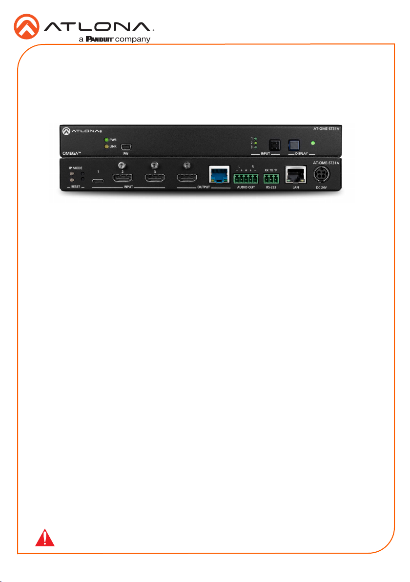
AT-OME-ST31A
The Atlona AT-OME-ST31A is a 3×1 switcher and HDBaseT transmitter with HDMI and USB-C
inputs. Part of the Omega™ Series of integration products for modern AV communications and
collaboration, it features mirrored HDMI and HDBaseT outputs, two-channel audio de-embedding
to an analog balanced audio output, and is HDCP 2.2 compliant. The USB-C input is ideal for
AV interfacing for newer Mac®, Chromebook™, and Windows® PCs, as well as smartphones
and tablets. Video signals up to 4K/60 4:2:0 can be transmitted over HDBaseT up to 330 feet
(100 meters). All inputs and the local HDMI output support 4K HDR and 4K/60 4:4:4 at HDMI
data rates up to 18 Gbps. Additionally, 4K downscaling to 1080p is available for the HDMI output
when connected to an HD sink. The OME-ST31A is designed for use with Omega™ Series
receivers and switchers, select HDVS Series receivers, the AT-UHD-EX-100CE-RX receiver, and
other Atlona switchers with HDBaseT inputs.
Package Contents
1 x AT-OME-ST31A
1 x USB-C cable
1 x Captive screw connector, 5-pin
1 x Captive screw connector, 3-pin
2 x Mounting brackets
4 x Mounting screws
1 x Installation Guide
IMPORTANT: Visit http://www.atlona.com/product/AT-OME-ST31A for the latest rm-
ware updates and Installation Guide.
1
INPUTFW
3
2
1
PWR
LINK
OMEGA
TM
AT-OME-ST31A
DISPLAY
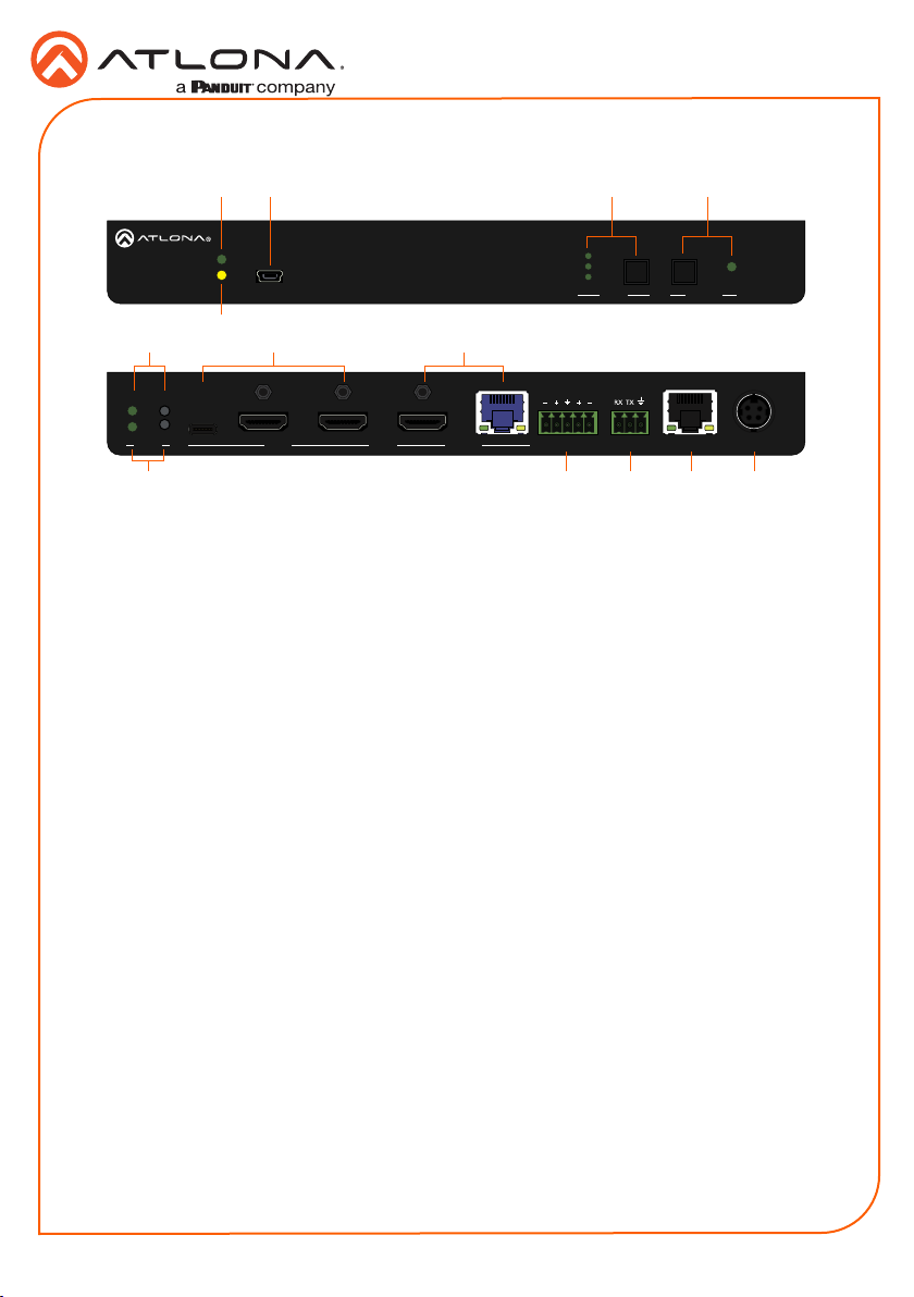
Panel Descriptions
Front
TM
OMEGA
6 98
Rear
IP MODE
RESET
7 1110 12 13
1 PWR
This LED indicator glows solid green when
the unit is powered.
2 LINK
This LED indicator glows solid yellow
when an HDBaseT link is established,
between the AT-OME-ST31A and the
receiver.
3 FW
Connect a mini-USB cable (not included)
from this port to update the rmware.
4 INPUT
Press and release this button to cycle
through each of the inputs. The LED
indicators will display the currently active
input, and correspond to each of the
numbered inputs on the rear panel of the
unit.
5 DISPLAY
Press this button to power-on or power-
o the connected display.
6 IP MODE
Press and release this button to set the IP
mode or display the current IP address.
Refer to IP Conguration (page 6) for
more information.
7 RESET
Press and release this button to reset the
unit to factory-default settings. Refer to
Resetting to Factory-Defaults (page 6) for
more information.
1
3 4 5
PWR
LINK
2
2
1
3
OUTPUT DC 24VINPUT
L R
AUDIO OUT LAN
8 INPUT ports
Connect a USB-C cable from a video
source to INPUT 1. Connect HDMI cables
from HD/UHD sources to INPUT 2 and
INPUT 3.
9 OUTPUT
Connect an HDMI from the HDMI port to
a display or other sink device. Connect a
category cable (CAT-5e or better), from the
HDBaseT port to a compatible HDBaseT
receiver. These ports are mirrored.
10 AUDIO OUT
Connect a 5-pin captive screw connector
block to this port, to de-embed audio to
an audio output device. Refer to Audio
Output Connector (page 3) for more
information.
11 RS-232
Connect a 3-pin captive screw block to
this port. Refer to RS-232 Connector
(page 3) for wiring information.
12 LAN
Connect an Ethernet cable to this port
from the network.
13 DC 24V
Connect the optional locking 24 V DC
power supply to this power receptacle.
1
2
3
Installation Guide
AT-OME-ST31A
INPUTFW
RS-232
DISPLAY
AT-OME-ST31A
AT-OME-ST31A
2

Installation Guide
GND GND
Side View Side View
RS-232 Connector
The AT-OME-ST31A provides an RS-232 port which can be used to control the unit or allow
command to pass through to a downstream device. Additionally, RS-232 commands can be
transmitted over HDBaseT to a PoE-compatible receiver unit.
NOTE: Typical DE-9 connectors use pin 2 for TX, pin 3 for RX, and pin 5 for
ground. On some devices functions of pins 2 and 3 are reversed.
1. Use wire strippers to remove a portion of the cable jacket.
2. Remove at least 3/16” (5 mm) from the insulation of the RX, TX, and GND wires.
3. Insert the TX, RX, and GND wires into correct terminal using the included 3-pin captive
screw connector.
TX
RX
GND
Audio Output Connector
AT-OME-ST31A
The AUDIO OUT connector on the AT-OME-ST31A provides the ability to de-embed audio to
an audio output device. Connect either balanced or unbalanced audio inputs, as shown below,
using the included 5-pin captive screw connector block.
Balanced audio connections use two signal wires and a ground to minimize interference in audio
signals. Unbalanced audio connections use one signal wire and a ground, and are used if system
components don’t support balanced signals.
Balanced Audio using XLR Connectors
+
2 1
3
-
+
GND
2 1
Rear View
3
-
+
Unbalanced Audio using RCA Connectors
-
+
GND
-
3
Rear View
Installation Guide
AT-OME-ST31A
Installation
1. Connect HDMI cables from HD/UHD sources to INPUT 2 and INPUT 3.
2. Connect a USB-C cable from a source to INPUT 1 on the switcher.
3. Connect an Ethernet cable, from the HDBaseT port to a compatible HDBaseT receiver.
NOTE: The AT-OME-ST31A is powered over HDBaseT, by a PoE receiver unit.
If a PoE HDBaseT receiver is not used, then the AT-OME-ST31A must be
powered using the external 24 V DC power supply* (not included). When used
with the external power supply, the AT-OME-ST31A can provide power to the
connected USB-C device. This power supply can be purchased from Atlona.
4. Connect an HDMI cable from the HDMI output port to a display or other sink device.
5. Connect an Ethernet cable from the LAN port to the Local Area Network.
6. OPTIONAL: Connect an audio output device to the AUDIO OUT port, using the included
captive screw connector block. Refer to Audio Output Connector (page 3) for wiring
information.
7. OPTIONAL: Connect an RS-232 cable from the control device to the RS-232 port on the
AT-OME-ST31A. Refer to RS-232 Connector (page 3) for wiring information.
* Optional power supply is available from Atlona. Part no. AT-PS-245-D4.
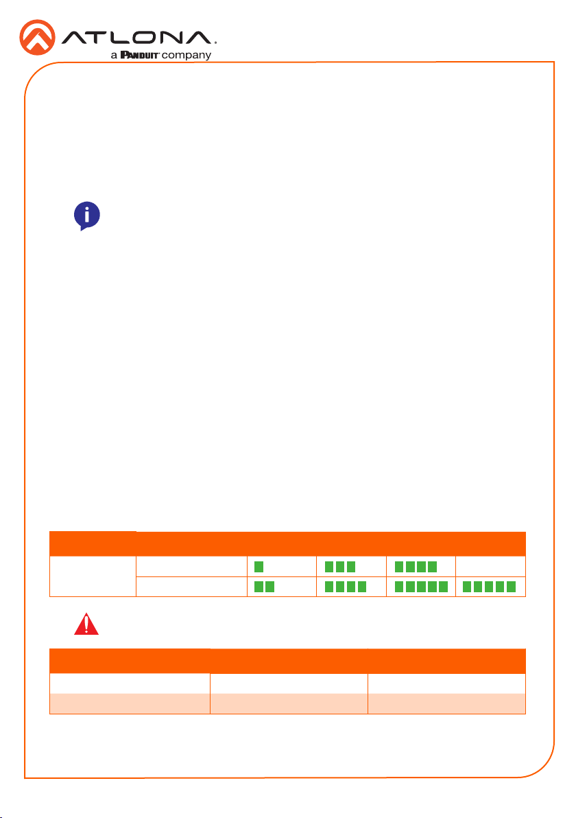
Cable Recommendation Guidelines
Refer to the tables below for recommended cabling when using Altona products with HDBaseT.
The green bars indicate the signal quality when using each type of cable. Higher-quality signals
are represented by more bars.
Core Shielding CAT5e CAT 6 CAT6a CAT7
Solid UTP (unshielded) N/A
STP (shielded)
IMPORTANT: Stranded or patch cables are not recommended due to
performance issues.
Cable* Max. Distance @ 4K Max. Distance @ 1080p
CAT5e 295 feet (90 meters) 330 feet (100 meters)
CAT6 / CAT6a / CAT7 330 feet (100 meters) 330 feet (100 meters)
*Atlona recommends TIA/EIA 568-B termination for optimal performance.
4
 Loading...