

Atlona Omega AT-OME-EX-KIT, Omega AT-OME-EX-TX, Omega AT-OME-EX-RX Installation Manual
1
Installation Guide
AT-OME-EX-KIT
Omega™ 4K/UHD
HDMI Over HDBaseT TX/RX with USB, Control, and PoE
AT-OME-EX-KIT
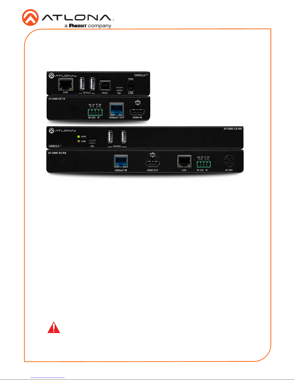
The Atlona AT-OME-EX-KIT is an HDBaseT extender for video up to 4K/60 4:2:0, plus
embedded audio, control, Ethernet, and USB 2.0 over distances up to 330 feet (100 meters).
Part of the Omega™ Series of integration products for modern AV communications and
collaboration, the OME-EX-KIT is HDCP 2.2 compliant and extends IR, RS-232, and IP control
signals. The integrated USB extension is ideal for software video conferencing and the use of
touch or interactive displays. The OME-EX-TX transmitter includes a USB host port for a PC,
plus two peripheral devices such as a speakerphone, microphone, or keyboard and mouse. The
OME-EX-RX receiver provides two USB 2.0 interfaces for devices such as a camera or display.
The transmitter and receiver are available separately, for use with other Omega Series integration
products.*
* Both the AT-OME-EX-TX and AT-OME-EX-RX are not compatible with the AT-UHD-HDVS-300
system for extending USB.
IMPORTANT: Visit http://www.atlona.com/product/AT-OME-EX-KIT for the
latest rmware updates and User Manual.
1 x AT-OME-EX-TX
1 x AT-OME-EX-RX
2 x Captive screw connectors, 4-pin
2 x Mounting plates
4 x Mounting screws
1 x 48 V DC power supply
1 x Installation Guide
Package Contents
2
Installation Guide
AT-OME-EX-KIT
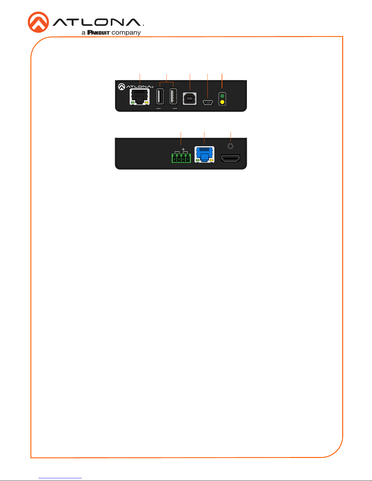
1 LAN
Connect a category cable from this port to a network switch. This cable provide IP passthrough transport control from a control system to the display (sink) device connected to the
receiver.
2 DEVICE
Connect up to two USB devices (e.g. mouse, keyboard, etc.) to these ports. Each port
provides 5 V / 500 mA.
3 HOST
Connect a USB cable from this port to the host computer.
4 FW
Connect a mini USB-to-USB cable from this port, to a computer, to update the rmware.
Refer to Updating the Firmware (page 10) for more information.
5 PWR / LINK
The PWR LED indicator will glow green when the AT-OME-EX-TX is powered. The AT-OMEEX-RX supplies power to the AT-OME-EX-TX over HDBaseT. The LINK LED indicator glows
yellow when a solid link is established between the transmitter and receiver. Refer to LED
Indicators (page 7) for more information.
6 RS-232 / IR
Connect the included 4-pin captive screw block to this receptacle. Refer to RS-232 and IR
(page 4) for more information.
7 HDBaseT OUT
Connect a category cable from this port to the HDBaseT IN port of the AT-OME-EX-RX or
other PoE-compatible receiver.
8 HDMI IN
Connect an HDMI cable from this port to the source device.
Front
Rear
LANHDBaseT IN DC 48V
AT-OME-EX-RX
HDMI OUT
HDMI IN
AT-OME-EX-TX
HDBaseT OUT
RX RXTX
RS-232 IR
8
6 7
LANHDBaseT IN DC 48V
AT-OME-EX-RX
HDMI OUT
LAN FWHOST
OMEGA
TM
DEVICE
PWR
LINK
PWR
HDMI IN
AT-OME-EX-TX
HDBaseT OUT
RX RXTX
RS-232 IR
2
1 3 4 5
AT-OME-EX-TX
3
Installation Guide
AT-OME-EX-KIT
LANHDBaseT IN DC 48V
AT-OME-EX-RX
HDMI OUT
RX TXTX
RS-232 IR
LANHDBaseT IN DC 48V
AT-OME-EX-RX
HDMI OUT
RX TXTX
RS-232 IR
AT-OME-EX-RX
FW
PWR
LINK
OMEGA
TM
DEVICE
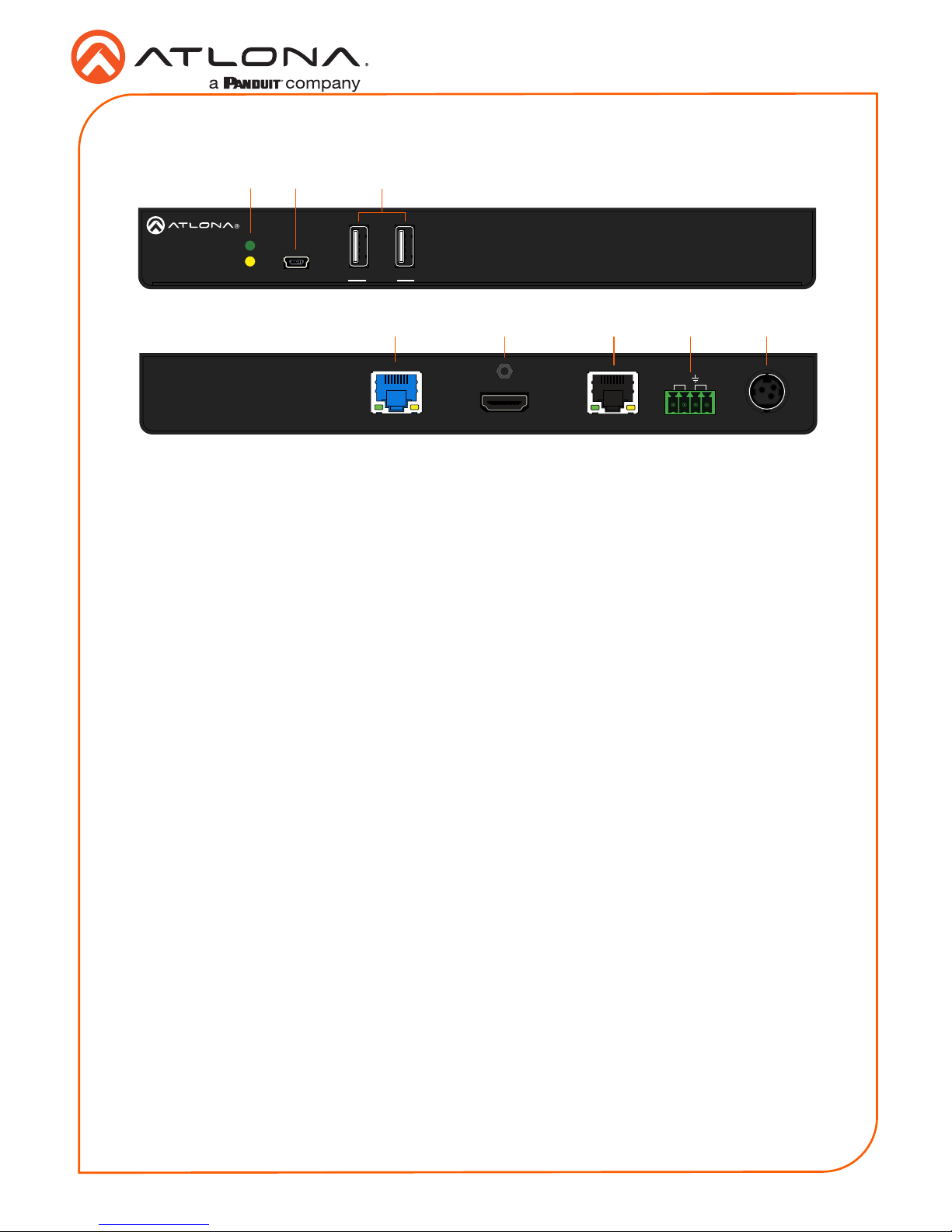
1 PWR / LINK
The PWR LED indicator will glow green when the AT-OME-EX-RX is powered. The LINK
LED indicator glows yellow when a solid link is established between the transmitter and
receiver. Refer to LED Indicators (page 7) for more information.
2 FW
Connect a mini USB-to-USB cable from this port, to a computer, to update the rmware.
Refer to Updating the Firmware (page 10) for more information.
3 DEVICE
Connect up to two USB 2.0 devices (e.g. mouse, keyboard, etc.) to these ports. Each port
provides 5 V / 500 mA.
4 HDBaseT IN
Connect a category cable from this port to the HDBaseT OUT port of the AT-OME-EX-TX.
The AT-OME-EX-TX is powered by the AT-OME-EX-RX over HDBaseT.
5 HDMI OUT
Connect an HDMI cable from this port to the display (sink) device.
6 LAN
Connect a category cable from this port to the display (sink) device. This cable provides IP
pass-through transport control to the display (sink) device, from a control system connected
to the transmitter.
7 RS-232 / IR
Connect the included 4-pin captive screw block to this receptacle. Refer to RS-232 and IR
(page 4) for more information.
8 DC 48V
Connect the included 48 V DC power supply to this power receptacle.
1
5
2 3
4 6 7 8
Front
Rear
AT-OME-EX-RX

4
Installation Guide
AT-OME-EX-KIT
The AT-OME-EX-KIT provides pass-through transport of RS-232 protocol and/or IR over
HDBaseT, which allows communication between a control system and an RS-232 or IR device.
This step is optional.
1. Use wire strippers to remove a portion of the cable jacket.
2. Remove at least 3/16” (5 mm) from the insulation of the RX, TX, and GND wires for the RS232 connection.
3. Insert the TX, RX, and GND wires into correct terminal using one of the included 4-pin
captive screw connectors.
4. Repeat step 2 for the S and GND wires for the IR connection.
5. Insert the S (signal) wire in to the TX terminal and the ground wire to the GND terminal.
6. Tighten the captive screws to secure the wires in place. Do not over-tighten or use hightorque devices to prevent damage to the connector block.
NOTE: Typical DB9 connectors use pin 2 for TX, pin 3 for RX, and pin 5 for
ground. On some devices functions of pins 2 and 3 are reversed. Note that the
signal (S) pin for the IR is labeled as “TX” on the port.
GND
to control system
or AT-VCC-IR-KIT
DE-9 (RS-232) port
RX
TX
S
GND
RS-232 and IR
 Loading...