

Atlona JunoX 451, JunoX 451 HDBT Installaiton Instructions
1
Installation Guide
AT-JUNO-451 / AT-JUNO-451-HDBT
4K HDR Fout-Input HDMI Switcher with Auto-Switching and
Return Optical Audio
AT-JUNO-451 / AT-JUNO-451-HDBT
1 x AT-JUNO-451
1 x 4-pin captive screw block
2 x Mounting plates
4 x Rubber feet
4 x Screws
1 x IR remote control
1 x DC 5V power supply
1 x IEC cord
1 x Installation Guide
1 x AT-JUNO-451-HDBT
1 x 4-pin captive screw block
2 x Mounting plates
4 x Rubber feet
4 x Screws
1 x IR remote control
1 x DC 5V power supply
1 x IEC cord
1 x Installation Guide
Package Contents
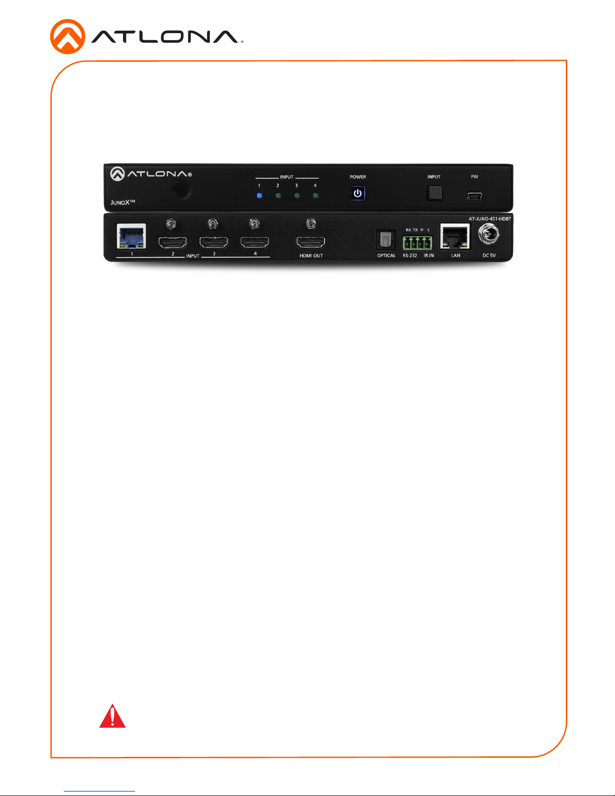
The Atlona JunoX™451 HDBT (AT-JUNO-451-HDBT) is a 4x1 switcher for high dynamic range
(HDR) formats. The JunoX 451 HDBT features three HDMI inputs, plus an HDBaseT input for
receiving video, embedded audio, and Ethernet over distances up to 330 feet (100 meters).
It is HDCP 2.2 compliant and supports 4K/UHD video @ 60 Hz with 4:4:4 chroma sampling,
as well as HDMI data rates up to 18 Gbps. The JunoX 451 HDBT is ideal for receiving 4K HDR
over HDBaseT from an Atlona Opus™ Series matrix switcher, and is also compatible with the
Atlona UHD-PRO3, UHD-CAT, and SW Series for data rates up to 10 Gbps. It includes EDID
management features and automatic input switching. The JunoX 451 HDBT also supports
the HDMI Audio Return Channel for receiving digital audio from a television,and includes a
TOSLINK digital audio output for sending this audio to an AV receiver or soundbar. This JunoX
Series switcher can be controlled via Ethernet, RS-232, and IR. A handheld IR remote control is
included.
The Atlona JunoX™ 451 (AT-JUNO-451) provides the same features at the AT-JUNO-451-HDBT,
except that the HDBaseT input is replaced with an HDMI port.
IMPORTANT: Visit http://www.atlona.com/product/AT-JUNO-451-HDBT and
http://www.atlona.com/product/AT-JUNO-451 for the latest rmware updates
and User Manual.
AT-JUNO-451 AT-JUNO-451-HDBT
2
Installation Guide
AT-JUNO-451 / AT-JUNO-451-HDBT
HDMI OUT LANOPTICAL RS-232
RX TX S
IR IN DC 5V
AT-JUNO-451-HDBT
INPUT
1 2
3
4
POWER INPUT FW
1 2 3 4
INPUT
AT-JUNO-451-HDBT
JUNOX
TM
HDMI OUT LANOPTICAL RS-232
RX TX S
IR IN
DC 5V
AT-JUNO-451-HDBT
INPUT
1 2
3
4
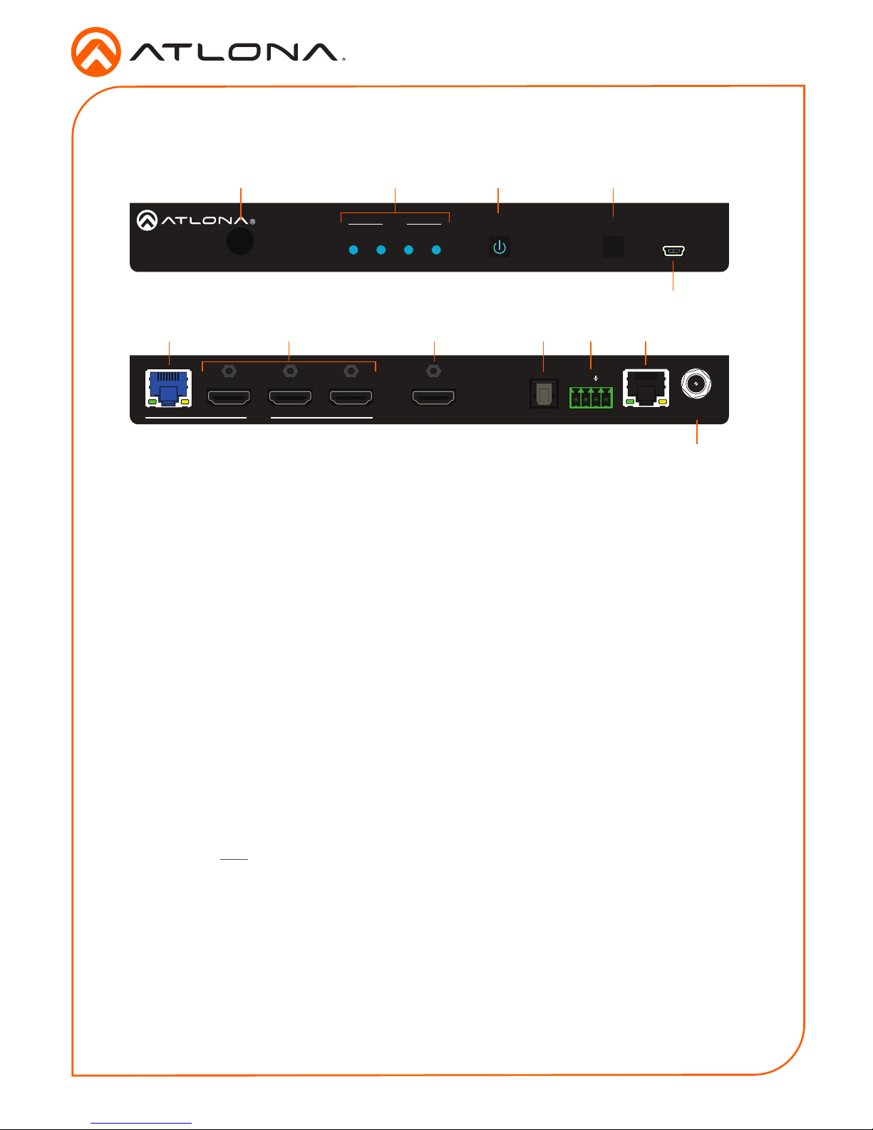
1 IR Window
Receives IR signals from the included IR
remote. Refer to RS-232 / IR Connector
(page 3) for wiring information.
2 Input Indicators
These LED indicators glow solid blue to
indicate the active input.
3 POWER
Press this button to power-on or power-
o the unit.
4 INPUT
Press and release this button to cycle
through each of the inputs.
5 FW
Connect a mini USB cable to this port to
update the rmware.
6 HDBaseT Input
This port is only available on the AT-
JUNO-451-HDBT: Connect a transmitter,
such as the AT-UHD-PRO3-44M, to this
port using an Ethernet cable.
The AT-JUNO-451 replaces this port with
an HDMI input.
7 HDMI Inputs
Connect an HD/UHD source to each of
these HDMI ports.
8 HDMI OUT
Connect an HDMI cable from this port to
a display or other sink device. This output
supports multichannel audio.
9 OPTICAL
Connect an optical audio cable from this
TOSLINK port to an audio output device.
This port is part of the Audio Return
Channel (ARC): audio from the display
is routed upstream, back to the switcher
over HDMI, to this port.
10 RS-232 / IR IN
Connect the included 4-pin captive
screw block to this port. Refer to RS-232
/ IR Connector (page 3) for wiring
information.
11 LAN
Connect an Ethernet cable from this port
to a Local Area Network (LAN).
12 DC 5V
Connect the included 5 V DC power
supply to this power receptacle.
Panel Descriptions (AT-JUNO-451-HDBT shown)
1
6
2
7
3
8
4
9 10 11
5
12

3
Installation Guide
AT-JUNO-451 / AT-JUNO-451-HDBT
RS-232 / IR Connector
Both the AT-JUNO-451 and AT-JUNO-451-HDBT both provide RS-232 and IR control, using the
included four-pin captive screw block. IR or RS-232 can be connected to a control system when
using external control.
1. Use wire strippers to remove a portion of the cable jacket.
2. Remove at least 3/16” (5 mm) from the insulation of each wire.
3. Insert the wires into the correct terminal on the included captive screw block, as shown
below.
4. Tighten the screws to secure the wires. Do not use high-torque devices as this may
damage the screws and/or connector block.
Both the AT-JUNO-451 and AT-JUNO-451-HDBT include an
IR remote control that can be used to operate the unit from
a remote location.
GND
to control system
or AT-VCC-IR-KIT
RX
TX
S
GND
IR Remote Control
SW-R1
Video 1
Video
Video 2
All On
Power
Vol +
Vol
-
Mute
1
324
5
Input
Audio
On
Off
On
Off
On
Off
1 On / O buttons
Press the On button to power-on the unit. Press the
O button to power-o the unit.
2 Input
Press these buttons (1 - 4) to select the desired input.
1
2
 Loading...