

Atlona AT-HDWP-IR, HDBaseT AT-HDWP, HDBaseT AT-HDWP-IR User Manual
User Manual
Atlona HDBaseT
Wall Plate Receivers
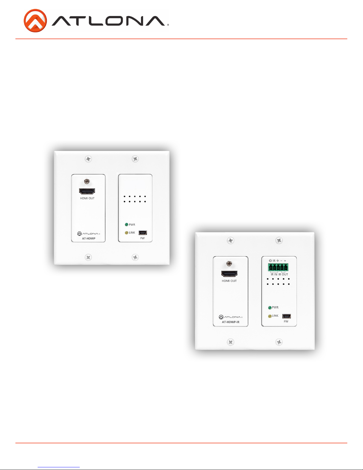
AT-HDWP, AT-HDWP-IR
AT-HDWP
AT-HDWP-IR
atlona.com
Toll free: 1-877-536-3976
Local: 1-408-962-0515

2
1. Introduction ................................................................................... 3
2. Package Contents ................................................................................... 3
3. Features ................................................................................... 3
4. Panel Descriptions ................................................................................... 4
5. Electrical Box ................................................................................... 4
6. Wall plate installation ................................................................................... 5-6
7. Captive Screw ................................................................................... 7
8. Connection ................................................................................... 8-10
9. Specifications ................................................................................... 11
10. Safety Information ................................................................................... 12
11. Warranty ................................................................................... 13-14
12. Atlona Product Registration ................................................................................... 14
atlona.com
Toll free: 1-877-536-3976
Local: 1-408-962-0515
Table of Contents

3
atlona.com
Toll free: 1-877-536-3976
Local: 1-408-962-0515
Introduction
Extend uninterrupted 1080p signal up to 230ft (70m) with the Atlona HDBaseT Wall Plate
Receivers. With pass through support of 4Kx2K, 1920x1200, lossy & lossless audio, and
bi-directional IR* signals over a single category cable, the HD extenders provide affordable, high
quality, solutions for your audio/video and IR* control needs.
Package Contents
Features
• 1 x AT-HDWP Receiver
• 1 x Decora® Faceplate
• 1 x Female Captive Screw Connector (5 pin*)
• 4 x 5/16” Phillips head screws for electrical box
• 4 x 5/16” PK/20 screws for the face plate
• 1 x IR Emitter (HDWP-IR only)
• 1 x IR Receiver (HDWP-IR only)
• 1 x User Manual
• Extends IR and audio/visual content up to 230ft @ 1080p over a single category cable
• Supports 4Kx2K pass through
• Built to be hidden, the wall plate form allows the receiver to be hidden behind wall mounted TVs
• USB updating for easy, in the field, firmware updates
• Captive screw IR I/O ports for emitting and receiving IR control signals for use with IR remote
controls and 3rd party control boxes (HDWP-IR only)
• PoCc (Power over Category cable) feature removes the need for a power supply when paired with
a compatible transmitter. (Ex. HDTX, HDTX-IR, PRO3HD44M, etc.)
• Lossy and lossless multi-channel audio formats pass through (including Dolby TrueHD and
DTS-HD Master Audio)
• Full 3D pass through
• HDCP compliant
* IR extender versions only
4
Electrical Box
Compatible electrical boxes (see below)
Type: Plastic old-work electrical box or mud ring
Size: 2 Gang
Dimensions: Inner opening must be greater than 3.58” wide and 2.68” high
atlona.com
Toll free: 1-877-536-3976
Local: 1-408-962-0515
LINK
FW
HDMI OUT
AT-HDWP-IR
PWR
IR IN
IR
IR OUT
-
+
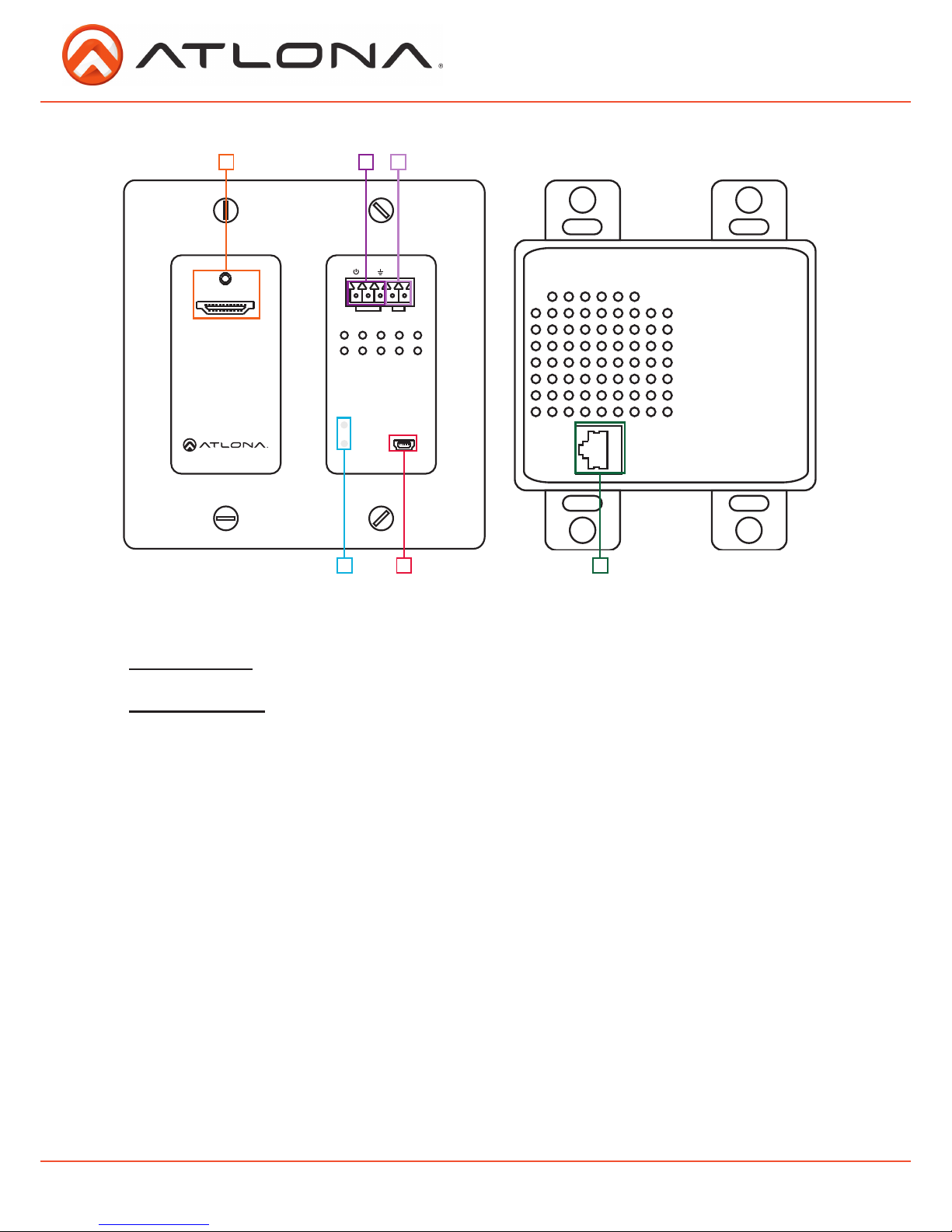
Panel Description
1. HDMI OUT Port: Connect to HDMI display.
2. IR IN Port: Connect the IR receiver to this port.*
3. IR OUT Port: Connect the IR Emitter to this port.*
4. Yellow Link LED: Signal Indicator for the CAT5e/6/7 OUT port. LED will remain solid, unless there
is an issue with the cable or signal, then it will blink.
Green Power LED: Power indicator. If plugged in light will remain solid. If LED starts blinking
power is intermittent or there is a problem with the cable. If LED is off, no power is passing to
the receiver (check your outlet or the power cable).
5. Firmware Update Port: Use a Mini USB to USB A cable to connect to a Windows computer for
updating.
6. CAT5e/6/7 IN Port: Connect a category cable from a compatible transmitter to this port.
1
4
2
5 6
3
*For IR products only

5
Wall Plate Installation
There are four pieces that will need to be interconnected in order for the AT-HDWP / AT-HDWP-IR
to be installed in the wall. The electrical box (picture A), the Decora HDBaseT module (picture B),
the Decora face plate (picture C) and the CAT cable.
The first step in installation is to connect the cat cable to the Decora HDBaseT module and install it
into the electrical box (as seen above).
Note: Use the four 5/16” Phillips head screws to install into the electrical box, these screws will be
unpainted.
A
B
C
atlona.com
Toll free: 1-877-536-3976
Local: 1-408-962-0515
 Loading...