

Atlona Gain 120, AT-GAIN-120 User Manual
Atlona Manuals
Audio
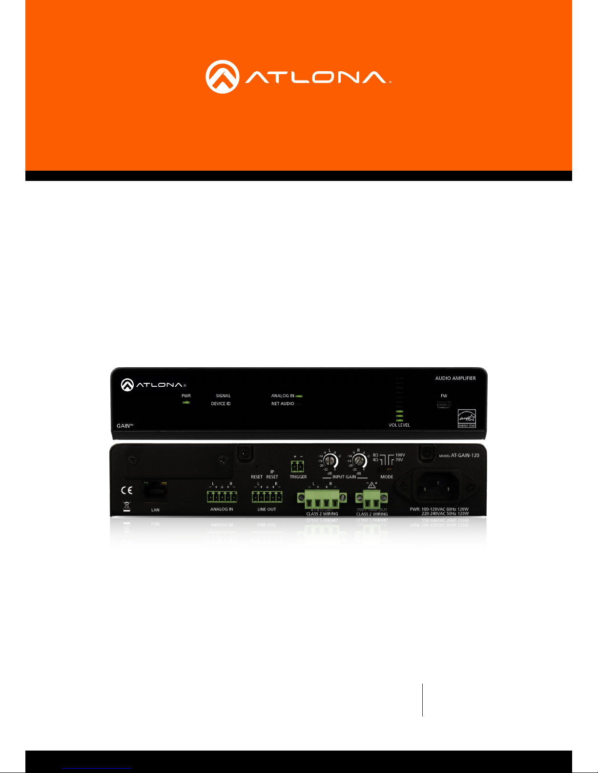
AT-GAIN-120
Audio Power Amplier
Stereo / Mono
120 Watts

AT-GAIN-120
2
Version Release Date Notes
1 4/18 Initial release
Version Information

AT-GAIN-120
3
©2018 Atlona, Inc. All Rights Reserved. All trademarks are the property of their respective owners.
Atlona reserves the right to make changes to the hardware, packaging, and documentation without notice.
Thank you for purchasing this Atlona product. We hope you enjoy it and will take an extra few moments to register
your new purchase.
Registration only takes a few minutes and protects this product against theft or loss. In addition, you will receive
notications of product updates and rmware. Atlona product registration is voluntary and failure to register will not
aect the product warranty.
To register your product, go to http://www.atlona.com/registration
Sales, Marketing, and Customer Support
Welcome to Atlona!
Operating Notes
IMPORTANT: Visit http://www.atlona.com/product/AT-GAIN-120 for the latest rmware updates and
User Manual.
Main Oce
Atlona Incorporated
70 Daggett Drive
San Jose, CA 95134
United States
Oce: +1.877.536.3976 (US Toll-free)
Oce: +1.408.962.0515 (US/International)
Sales and Customer Service Hours
Monday - Friday: 6:00 a.m. - 4:30 p.m. (PST)
http://www.atlona.com/
International Headquarters
Atlona International AG
Ringstrasse 15a
8600 Dübendorf
Switzerland
Oce: +41 43 508 4321
Sales and Customer Service Hours
Monday - Friday: 09:00 - 17:00 (UTC +1)

AT-GAIN-120
4
Atlona, Inc. (“Atlona”) Limited Product Warranty
Coverage
Atlona warrants its products will substantially perform to their published specications and will be free from defects
in materials and workmanship under normal use, conditions and service.
Under its Limited Product Warranty, Atlona, at its sole discretion, will either:
• repair or facilitate the repair of defective products within a reasonable period of time, restore products to their
proper operating condition and return defective products free of any charge for necessary parts, labor and
shipping.
OR
• replace and return, free of charge, any defective products with direct replacement or with similar products
deemed by Atlona to perform substantially the same function as the original products.
OR
• refund the pro-rated value based on the remaining term of the warranty period, not to exceed MSRP, in cases
where products are beyond repair and/or no direct or substantially similar replacement products exist.
Repair, replacement or refund of Atlona products is the purchaser’s exclusive remedy and Atlona liability does not
extend to any other damages, incidental, consequential or otherwise.
This Limited Product Warranty extends to the original end-user purchaser of Atlona products and is non-transferrable
to any subsequent purchaser(s) or owner(s) of these products.
Coverage Periods
Atlona Limited Product Warranty Period begins on the date of purchase by the end-purchaser. The date contained on
the end-purchaser ‘s sales or delivery receipt is the proof purchase date.
Limited Product Warranty Terms – New Products
• 10 years from proof of purchase date for hardware/electronics products purchased on or after June 1, 2013.
• 3 years from proof of purchase date for hardware/electronics products purchased before June 1, 2013.
• Lifetime Limited Product Warranty for all cable products.
Limited Product Warranty Terms – Refurbished (B-Stock) Products
• 3 years from proof of purchase date for all Refurbished (B-Stock) hardware and electronic products purchased
on or after June 1, 2013.
Remedy
Atlona recommends that end-purchasers contact their authorized Atlona dealer or reseller from whom they
purchased their products. Atlona can also be contacted directly. Visit www.atlona.com for Atlona’s contact
information and hours of operation. Atlona requires that a dated sales or delivery receipt from an authorized dealer,
reseller or end-purchaser is provided before Atlona extends its warranty services. Additionally, a return merchandise
authorization (RMA) and/or case number, is required to be obtained from Atlona in advance of returns.
Atlona requires that products returned are properly packed, preferably in the original carton, for shipping. Cartons not
bearing a return authorization or case number will be refused. Atlona, at its sole discretion, reserves the right to reject
any products received without advanced authorization. Authorizations can be requested by calling 1-877-536-3976
(US toll free) or 1-408- 962-0515 (US/international) or via Atlona’s website at www.atlona.com.
Exclusions
This Limited Product Warranty excludes:
• Damage, deterioration or malfunction caused by any alteration, modication, improper use, neglect, improper
packaging or shipping (such claims must be presented to the carrier), lightning, power surges, or other acts of
nature.

AT-GAIN-120
5
• Damage, deterioration or malfunction resulting from the installation or removal of this product from any
installation, any unauthorized tampering with this product, any repairs attempted by anyone unauthorized by
Atlona to make such repairs, or any other cause which does not relate directly to a defect in materials and/or
workmanship of this product.
• Equipment enclosures, cables, power supplies, batteries, LCD displays, and any accessories used in conjunction
with the product(s).
• Products purchased from unauthorized distributors, dealers, resellers, auction websites and similar unauthorized
channels of distribution.
Disclaimers
This Limited Product Warranty does not imply that the electronic components contained within Atlona’s products
will not become obsolete nor does it imply Atlona products or their electronic components will remain compatible
with any other current product, technology or any future products or technologies in which Atlona’s products may
be used in conjunction with. Atlona, at its sole discretion, reserves the right not to extend its warranty oering in
instances arising outside its normal course of business including, but not limited to, damage inicted to its products
from acts of god.
Limitation on Liability
The maximum liability of Atlona under this limited product warranty shall not exceed the original Atlona MSRP for
its products. To the maximum extent permitted by law, Atlona is not responsible for the direct, special, incidental or
consequential damages resulting from any breach of warranty or condition, or under any other legal theory. Some
countries, districts or states do not allow the exclusion or limitation of relief, special, incidental, consequential or
indirect damages, or the limitation of liability to specied amounts, so the above limitations or exclusions may not
apply to you.
Exclusive Remedy
To the maximum extent permitted by law, this limited product warranty and the remedies set forth above are
exclusive and in lieu of all other warranties, remedies and conditions, whether oral or written, express or implied.
To the maximum extent permitted by law, Atlona specically disclaims all implied warranties, including, without
limitation, warranties of merchantability and tness for a particular purpose. If Atlona cannot lawfully disclaim
or exclude implied warranties under applicable law, then all implied warranties covering its products including
warranties of merchantability and tness for a particular purpose, shall provide to its products under applicable law.
If any product to which this limited warranty applies is a “Consumer Product” under the Magnuson-Moss Warranty
Act (15 U.S.C.A. §2301, ET SEQ.) or other applicable law, the foregoing disclaimer of implied warranties shall not
apply, and all implied warranties on its products, including warranties of merchantability and tness for the particular
purpose, shall apply as provided under applicable law.
Other Conditions
Atlona’s Limited Product Warranty oering gives legal rights, and other rights may apply and vary from country to
country or state to state. This limited warranty is void if (i) the label bearing the serial number of products have been
removed or defaced, (ii) products are not purchased from an authorized Atlona dealer or reseller. A comprehensive
list of Atlona’s authorized distributors, dealers and resellers can be found at www.atlona.com.
Atlona, Inc. (“Atlona”) Limited Product Warranty

AT-GAIN-120
6
Important Safety Information
The lightning ash with arrowhead symbol, within an equilateral triangle, is intended to alert the user to the presence
of uninsulated “dangerous voltage” within the product’s enclosure that may be of sucient magnitude to constitute a
risk of electric shock to persons.
Das Symbol des Blitzzeichens innerhalb eines gleichseitigen Dreiecks soll den Benutzer davor warnen, dass
innerhalb des Gehäuses gefährlich hohe Spannung an berührbaren Teilen anliegt. Die Spannung ist hoch genug um
bei Berührung zu einem gefährlichen elektrischen Schlag zu führen!
Le ash lumineux dans le symbole de la èche du triangle équilatéral est destiné à alerter l’utilisateur de la présence
d’une «tension dangereuse» non isolée dans l’enceinte du produit qui peut être susamment importante pour
constituer un risque d’électrocution pour les personnes
Il simbolo del lampo con la punta di una freccia, all’interno di un triangolo equilatero, avvisa l’utente della presenza di
“tensioni pericolose” non isolate all’interno del contenitore del prodotto che possono essere sucientemente elevate
da costituire un rischio di folgorazione per le persone.
El símbolo del rayo con punta de echa dentro de un triángulo equilátero alerta al usuario de la presencia de “voltaje
peligroso” no aislado en el interior del producto que puede ser de una magnitud suciente como para constituir un
riesgo de descarga eléctrica para las personas.
Вспышка молнии с символом стрелки в треугольнике предназначена для предупреждения пользователя о
наличии неизолированного «опасного напряжения» в корпусе продукта, которое может иметь достаточную
величину, чтобы представлять опасность поражения электрическим током для людей
三角形內帶有箭頭符號的閃電,旨意在提醒用戶產品外殼內存在未絕緣的“危險電壓”可能會造成人體觸電危險
AT-GAIN-120
7
FCC Statement
FCC Compliance and Advisory Statement: This hardware device complies with
Part 15 of the FCC rules. Operation is subject to the following two conditions: 1)
this device may not cause harmful interference, and 2) this device must accept any
interference received including interference that may cause undesired operation. This
equipment has been tested and found to comply with the limits for a Class A digital
device, pursuant to Part 15 of the FCC Rules. These limits are designed to provide
reasonable protection against harmful interference in a commercial installation.
This equipment generates, uses, and can radiate radio frequency energy and, if not
installed or used in accordance with the instructions, may cause harmful interference
to radio communications. However there is no guarantee that interference will not occur in a particular installation. If
this equipment does cause harmful interference to radio or television reception, which can be determined by turning
the equipment o and on, the user is encouraged to try to correct the interference by one or more of the following
measures: 1) reorient or relocate the receiving antenna; 2) increase the separation between the equipment and the
receiver; 3) connect the equipment to an outlet on a circuit dierent from that to which the receiver is connected;
4) consult the dealer or an experienced radio/TV technician for help. Any changes or modications not expressly
approved by the party responsible for compliance could void the user’s authority to operate the equipment. Where
shielded interface cables have been provided with the product or specied additional components or accessories
elsewhere dened to be used with the installation of the product, they must be used in order to ensure compliance
with FCC regulations.
1. Read these instructions.
2. Keep these instructions.
3. Heed all warnings.
4. Follow all instructions.
5. Do not use this product near water.
6. Clean only with a dry cloth.
7. Do not block any ventilation openings. Install in
accordance with the manufacturer’s instructions.
8. Do not install or place this product near any heat
sources such as radiators, heat registers, stoves, or
other apparatus (including ampliers) that produce
heat.
9. Do not defeat the safety purpose of a polarized
or grounding-type plug. A polarized plug has two
blades with one wider than the other. A grounding
type plug has two blades and a third grounding
prong. The wide blade or the third prong are
provided for your safety. If the provided plug does
not t into your outlet, consult an electrician for
replacement of the obsolete outlet.
10. Protect the power cord from being walked on
or pinched particularly at plugs, convenience
receptacles, and the point where they exit from the
product.
11. Only use attachments/accessories specied by
Atlona.
12. To reduce the risk of electric shock and/or damage
to this product, never handle or touch this unit or
power cord if your hands are wet or damp. Do not
expose this product to rain or moisture.
13. Unplug this product during lightning storms or when
unused for long periods of time.
14. Refer all servicing to qualied service personnel.
Servicing is required when the product has been
damaged in any way, such as power-supply cord or
plug is damaged, liquid has been spilled or objects
have fallen into the product, the product has been
exposed to rain or moisture, does not operate
normally, or has been dropped.
CAUTION: TO REDUCT THE RISK OF
ELECTRIC SHOCK
DO NOT OPEN ENCLOSURE OR EXPOSE
TO RAIN OR MOISTURE.
NO USER-SERVICEABLE PARTS
INSIDE REFER SERVICING TO
QUALIFIED SERVICE PERSONNEL.
CAUTION
RISK OF ELECTRIC SHOCK
DO NOT OPEN
The exclamation point within an equilateral triangle is intended to alert the user to
the presence of important operating and maintenance instructions in the literature
accompanying the product.
The information bubble is intended to alert the user to helpful or optional operational instructions in the literature accompanying the product.
Important Safety Information

AT-GAIN-120
8
Introduction 9
Features 9
Package Contents 9
Panel Description 10
Installation 11
Audio Connectors 11
ANALOG IN / LINE OUT 11
4 / 8 Ω OUT 11
70V / 100V OUT 12
Trigger 12
Connection Instructions 13
Connection Diagram 14
Basic Operation 15
IP Conguration 15
Using the Rear Panel 15
Using Commands 16
Using the Web GUI 17
LED Indicators 19
Power Modes 20
Powering On or O 20
Auto Power Down mode 20
Hibernation mode 21
Network Audio 22
Dante Software Conguration 22
Enabling AES67 Support 23
Volume Control 25
Factory Reset 25
The Web GUI 26
Introduction to the Web GUI 26
Menu Bar 27
Status page 28
Firmware page 29
Network page 30
Control page 31
Users page 32
Audio page 33
Appendix 34
Updating the Firmware 34
Web GUI 34
USB 36
Rack Mount Installation 37
Network Audio Card Installation 38
Default Settings 41
Specications 42
Index 44
Table of Contents

AT-GAIN-120
9
The Atlona Gain™ 120 (AT-GAIN-120) is a compact power amplier designed for low or high impedance
applications. A mode selector switch allows it to deliver two channels of 60 watts each into 4 or 8 ohms, or a single
channel of 120 watts at 70 or 100 volts. This Class-D amplier is energy ecient, ENERGY STAR® qualied, and is
also convection-cooled to allow installation in conference rooms and quiet installation environments without the need
for fans. In addition to the amplied speaker output, a line level audio output allows the incoming audio to be fed
into an additional amplier or audio system. The Gain 120 is controllable via TCP/IP or external trigger, and can be
integrated with Atlona AV switchers and HDBaseT™ receivers for a wide variety of sound reinforcement applications.
Introduction
Features
Package Contents
• Selectable low or high-impedance operation.
» 2 x 60 watts @ 4 or 8 ohms.
» 1 x 120 watts @ 70 or 100 volts.
• Class-D ecient amplier design.
• ENERGY STAR® qualied.
• Convection cooled – no need for fans.
• Available AES67 / Dante™ networked audio interface (AT-GAIN-NET) – receives two-channel audio from
OmniStream AV encoders or compatible audio devices.
• Optional AT-RACK-1RU rack shelf highly recommended for rack installation.
• Automatic standby after 25 minutes of inactivity to minimize power consumption.
• Rear panel input level controls for setting audio system gain staging.
• Integrated protection circuitry automatically activates in the event of clipping, short circuit, thermal overload,
and more.
• Low inrush current to prevent audible “thumps” when multiple amps are powered on simultaneously.
• Balanced analog audio output for pass-through to an additional amplier or audio system.
• Integrated ve-band equalizer.
• TCP/IP control of volume level, muting, and EQ.
• Ideal for IP-based control from Atlona Velocity Control System.
• Trigger port ideal for occupancy sensor to remotely power down amplier or wake from standby.
• Front panel signal status LEDs for power, signal presence, real-time volume level, device identication, and
internal protection activation.
• Rack-mountable 1U, half rack width enclosure.
• Includes installation guide, power cable (US), and captive screw connectors.
1 x AT-GAIN-120
2 x Captive screw connector, 2-pin
1 x Captive screw connector, 4-pin
2 x Captive screw connector, 5-pin
1 x IEC power cord
1 x Installation Guide
AT-GAIN-120
10
PWR
VOL LEVEL
AUDIO AMPLIFIER
FWSIGNAL ANALOG IN
NET AUDIODEVICE ID
GAIN
TM
PWR
VOL LEVEL
AUDIO AMPLIFIER
FWSIGNAL ANALOG IN
NET AUDIODEVICE ID
GAIN
TM
LAN
RESET RESET
LINE OUT
CLASS 2 WIRING CLASS 2 WIRING
TRIGGER MODE
MODEL:
dB
-22
-2
-4
-20
-19
-14
-9
-22
-2
-4
-20
-19
-14
-9
dB
ANALOG IN
L
4 / 8 Ω OUT 70V / 100V OUT
AT-GAIN-120
PWR: 100-120VAC 60Hz 120W
220-240VAC 50Hz 120W
L R L R
IP
4Ω
8Ω 100V
70V
R
INPUT GAIN
L R
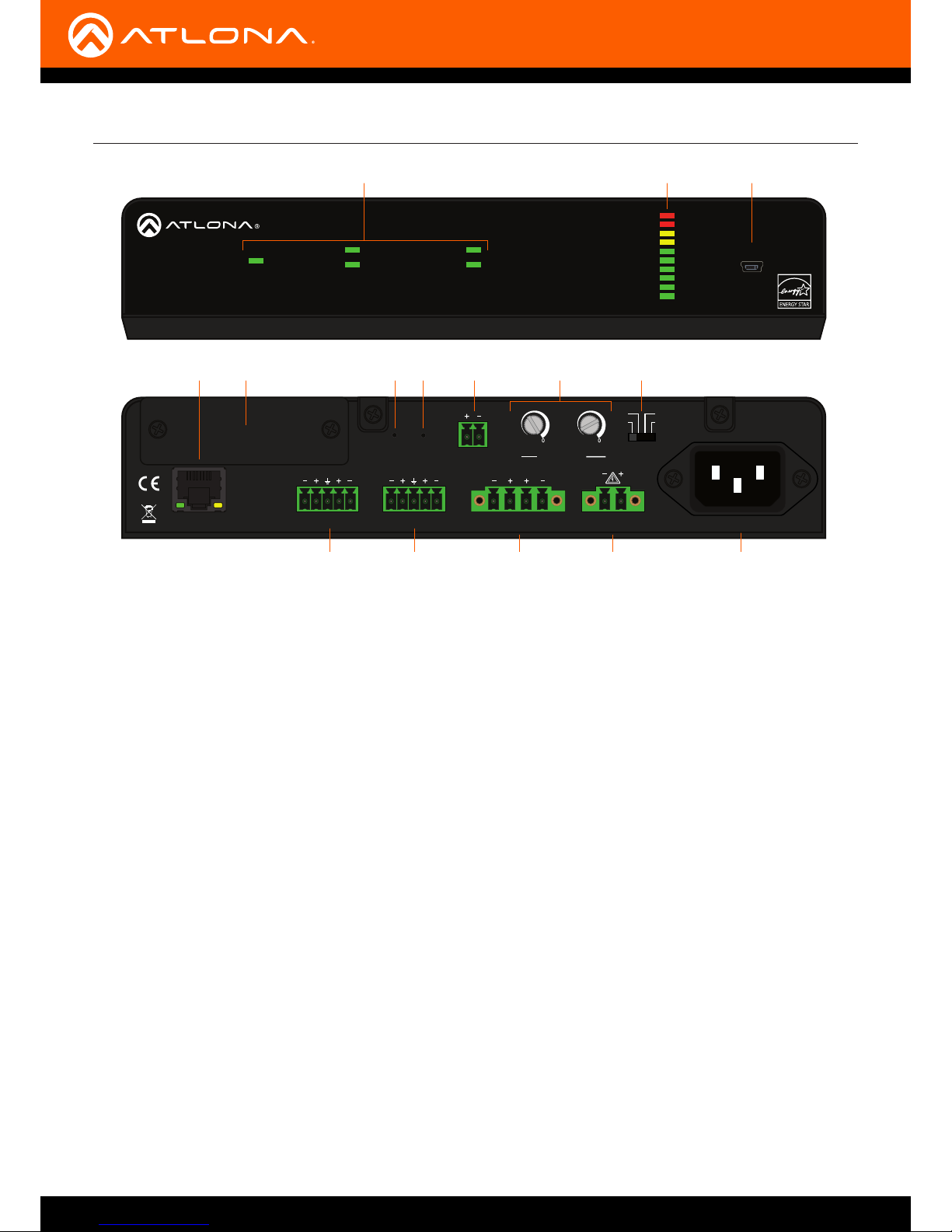
Panel Description
1
4
6 8 11 13 15
5 107 9 1412
2 3
Front
Rear
1 LED indicators
Displays the current state of the unit. Refer to LED
Indicators (page 19) for more information.
2 VOL LEVEL
Displays the output audio level.
3 FW
Connect a USB-to-mini USB cable to this port from a
computer for rmware updates.
4 LAN
Connect an Ethernet cable from this port to the Local
Area Network (LAN).
5 Removable Faceplate
Remove this faceplate to install the AT-GAIN-NET
(not included) card. Refer to Network Audio Card
Installation (page 38) for more information.
6 ANALOG IN
Connect an audio source to this port using the
included 5-pin captive screw connector. Refer to
Audio Connectors (page 11) for wiring information.
7 RESET
Press and hold this button for 10 seconds to reset
the unit to factory-default settings. Refer to Factory
Reset (page 25) for more information.
8 LINE OUT
Use the included 5-pin captive screw connector
to connect to another AT-GAIN-120, audio DSP, or
audio mixer. Refer to Audio Connectors (page 11)
for more information.
9 IP RESET
Press and hold button this button for 10 seconds to
switch between DHCP and static IP mode. Refer to
IP Conguration (page 15) for more information.
Also press and hold for 3 seconds to bring the unit
out of hibernation mode. Refer to Power Modes
(page 20) for more information.
10 TRIGGER
Use this port to toggle the unit between on and
standby or awaken the unit from hibernation mode.
11 4 / 8 Ω OUT
Connect a pair of 4 or 8 ohm speakers (lowimpedance) to this port using the included 4-pin
captive screw connector.
12 INPUT GAIN
Use a regular screwdriver to adjust the input gain
level for left and right channel.
13 70V / 100V OUT
Connect a distributed speaker system (highimpedance) to this port using the included 2-pin
captive screw connector.
14 MODE
Slide the switch to select between 4Ω, 8Ω, 70V, or
100V modes.
15 PWR
Connect from a power source to the AT-GAIN-120
using the included IEC power cord.
AT-GAIN-120
11
Installation
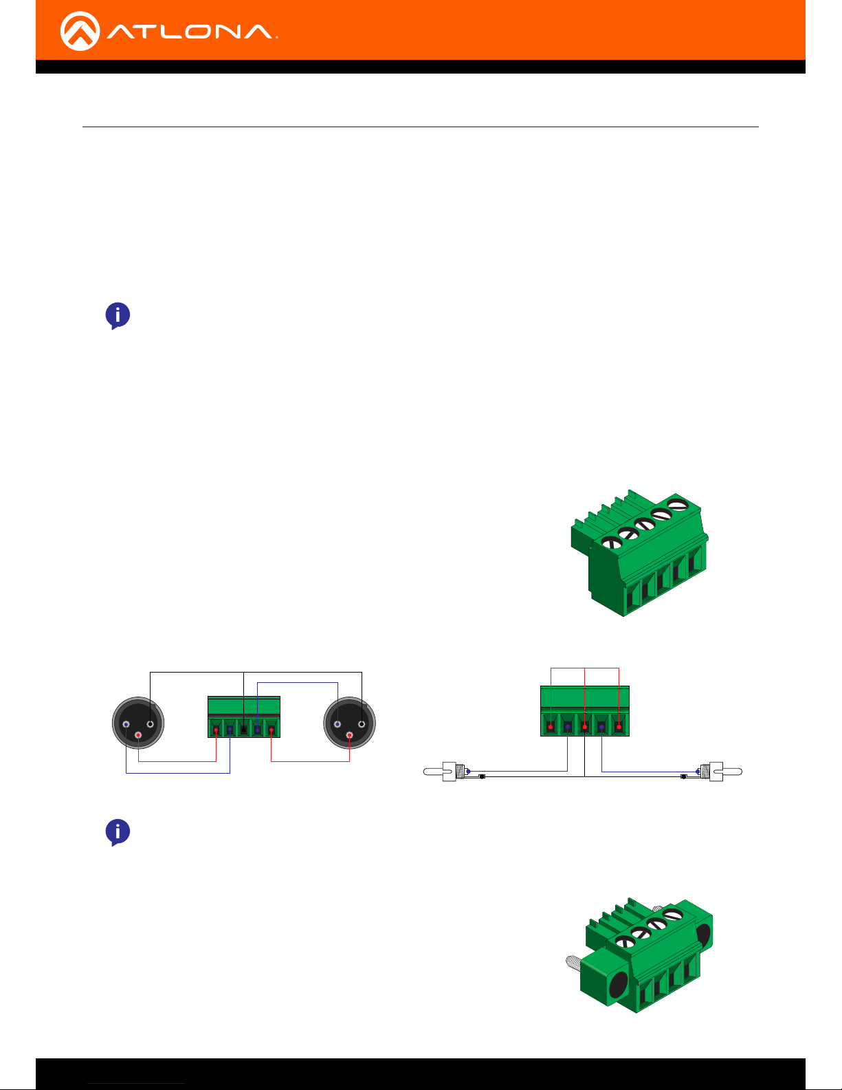
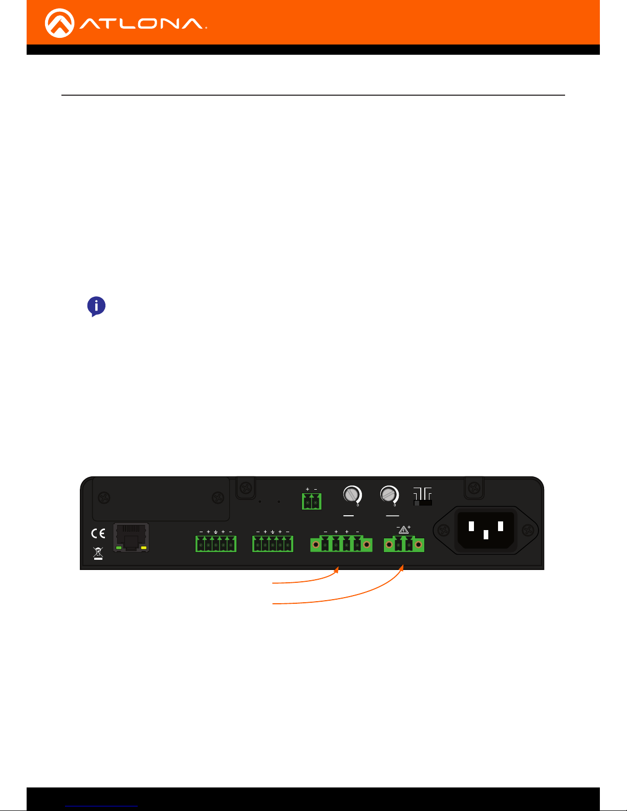
The AT-GAIN-120 provides two audio ports which provide analog audio input and output. The ANALOG IN port can
be used to connect an audio digital signal processor (DSP) or other audio source device. Balanced or unbalanced
wiring is supported.
The LINE OUT port can be used to connect an audio output device or daisy-chain to another amplier.
The wiring for the ANALOG IN and LINE OUT ports, support either
balanced or unbalanced audio, as shown below. Both ports use the
included 5-pin captive screw connectors.
Connect program/stereo speakers to the included 4-pin captive screw
connector, then connect the terminal block to the 4 / 8 Ω OUT port.
When connecting program / stereo speakers, set the MODE switch to
either 4 Ω or 8 Ω, depending upon the speakers impedance.
Audio Connectors
ANALOG IN / LINE OUT
4 / 8 Ω OUT
GND
Side View Side View
-
+
GND
+
-
2 1
3
2 1
3
GND GND
-
+
Rear View
Rear View
-
+
Balanced audio using XLR connectors Unbalanced audio using RCA connectors
1. Use wire strippers to remove a portion of the cable jacket.
2. Remove at least 3/16” (5 mm) from the insulation of each wire.
3. Connect the wires as shown, using either balanced or unbalanced wiring.
NOTE: The LINE OUT port is a xed-level analog output, only. There is no D/A conversion when
using the optional AT-GAIN-NET card.
NOTE: The LINE OUT port only outputs analog audio. This port cannot be used to output
digital audio from the optional AT-GAIN-NET card. Also, volume mute, using the web GUI or the
VOUTMute command, will mute the LINE OUT pass-through.

AT-GAIN-120
12
Installation
Trigger
The AT-GAIN-120 provides a TRIGGER port allowing the AT-GAIN-120 to be connected to an occupancy sensor.
Voltage levels for this port are as follows:
1. Use wire strippers to remove a portion of the cable jacket.
2. Remove at least 3/16” (5 mm) from the insulation of each wire.
3. Connect the wires as shown.
Voltage level Function
Voltage is 0 or less than 3 V O
Voltage is 3 V or greater (30 V max.) On
Connect a distributed speaker system to the included 2-pin captive
screw connector, then connect the terminal block to the 70V / 100V
OUT port. When connecting program / stereo speakers, set the MODE
switch to either 70V or 100V, depending upon the speakers.
70V / 100V OUT
AT-GAIN-120
13
PWR
VOL LEVEL
AUDIO AMPLIFIER
FWSIGNAL ANALOG IN
NET AUDIODEVICE ID
GAIN
TM
LAN
RESET RESET
LINE OUT
CLASS 2 WIRING CLASS 2 WIRING
TRIGGER MODE
MODEL:
dB
-22
-2
-4
-20
-19
-14
-9
-22
-2
-4
-20
-19
-14
-9
dB
ANALOG IN
L
4 / 8 Ω OUT 70V / 100V OUT
AT-GAIN-120
PWR: 100-120VAC 60Hz 120W
220-240VAC 50Hz 120W
L R L R
IP
4Ω
8Ω 100V
70V
R
INPUT GAIN
L R
1. Connect an analog audio source, using the included 5-pin captive screw connector, to the AUDIO IN port.
Use the desired wiring conguration, on the previous page. Both balanced and unbalanced wiring are
supported.
2. Connect an analog audio output device, using the included 5-pin captive screw connector, to the LINE OUT
port. Use the desired wiring conguration, on the previous page. Both balanced and unbalanced wiring are
supported.
3. Determine the use-case scenario of the AT-GAIN-120. The AT-GAIN-120 can be congured as either one of the
following. Only one type of speaker connection is permitted at a time.
• Distributed speaker system (high impedance)
Set the MODE switch to the required voltage setting: 70V or 100V. This mode is used for commercial
applications and longer speaker cable runs.
• Program speakers / stereo (low impedance)
Set the MODE switch to the impedance setting of the speakers being connected: 4Ω or 8Ω.
This mode is used for consumer applications and shorter speaker cable runs.
Connection Instructions
Installation
Program / stereo speakers (low impedance)
Distributed speakers (high impedance)
4. Connect the speakers to the proper port on the AT-GAIN-120, based on the selection made in the previous step.
5. Set the MODE switch to the proper setting, based on the type of speaker connection that is being used.
6. Connect the LAN port to a network switch for set up and control of the unit.
7. OPTIONAL: Connect the included 2-pin captive screw connector from the TRIGGER port to an automation
control system.
8. Connect the included IEC power cord to the power receptacle.
9. Connect the IEC power cable to an available electrical outlet.
The AT-GAIN-120 can be used with an optional network audio card, which supports Dante and AES76 audio streams.
If this card will be installed, refer to Network Audio Card Installation (page 38) for more information before
continuing with the following instructions. This network card is sold separately and is available from Atlona.
NOTE: Analog or NET audio (with optional card), are selectable from the web GUI, Atlona
Velocity™, or thrid-party control using the API. Refer to the Stereo / Mono Audio Power Amplifer
120 Watts Application Programming Interface, on the Atlona web site for more information.
In addtion, the LINE OUT port only outputs analog audio. This port cannot be used to output
digital audio from the optional AT-GAIN-NET card.
AT-GAIN-120
14
Installation
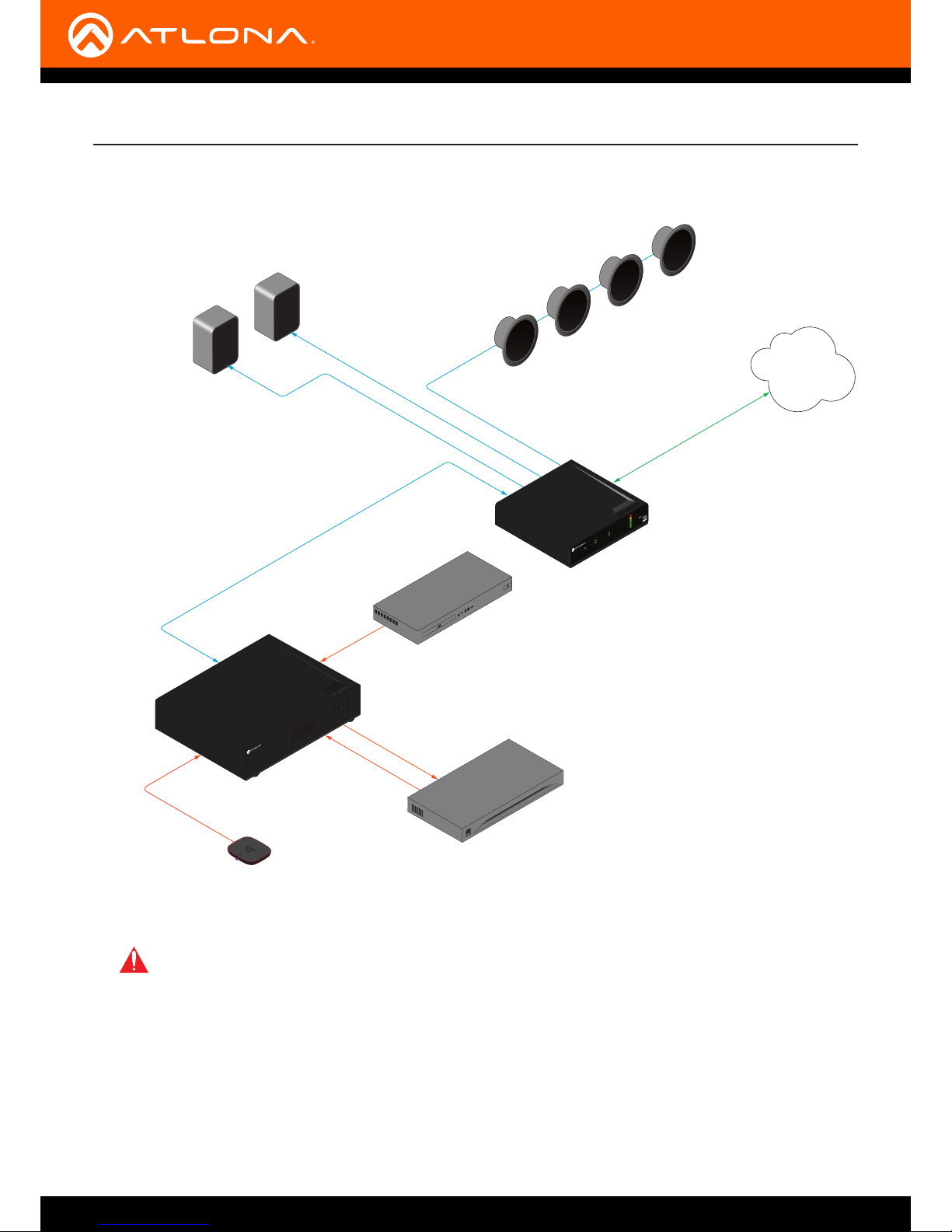
Connection Diagram
Program Speakers
Audio
Audio
Generic
SPEAKER SYSTEMS
Generic
SPEAKER SYSTEMS
LAN
AT-UHD-CLSO-840
HDMI
Audio
AT-UHD-CLSO-840
FCN CANCEL EDID
INFO
POWER ENTER
4
media4
Media Player
Codec
HDMI
HDMI
HDMI
I
0
Precision Hardware Codec
Blu-ray player
AT-GAIN-120
Distributed Speakers
Audio
Generic
SPEAKER SYSTEMSSPEAKER SYSTEMS
Generic
SPEAKER SYSTEMSSPEAKER SYSTEMS
Generic
SPEAKER SYSTEMSSPEAKER SYSTEMS
Generic
SPEAKER SYSTEMSSPEAKER SYSTEMS
PWR
VOL LEVEL
AUDIO AMPLIFIER
FWSIGNAL ANALOG IN
NET AUDIODEVICE ID
GAIN
TM
IMPORTANT: When connecting speakers, either use a distributed speaker system or program/
stereo speakers. The AT-GAIN-120 does not support simultaneous distributed and program speaker
connections.
 Loading...