

Atlona AT-VGA0801, AT-VGA0802-A, AT-VGA1608-A, AT-VGA9601 User Manual
www.atlona.com | toll free: 1-877-536-3976
For International: 1-408-962-0515
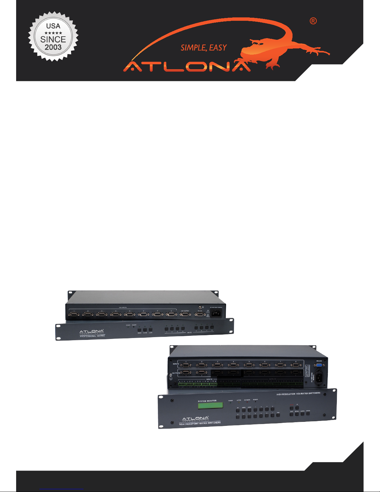
AT-VGA0801
AT-VGA0802-A
User Manual
AtlonA
VGA SWITCHERS:
AT-VGA0801 TO AT-VGA9601
VGA SWITCEHRS W/AUDIO:
AT-VGA0802-A TO AT-VGA1608-A

www.atlona.com | toll free: 1-877-536-3976
For International: 1-408-962-0515
2
TABLE OF CONTENTS
1. Introduction .................................................. 3
2. Installation .................................................. 3
3. Package Contents .................................................. 3
4. View of the Product .................................................. 4
4.1. Front View of Products .................................................. 4
4.1.1. Front View of AT-VGA0404-A .................................................. 4
4.1.2. Front View of AT-VGA0801 .................................................. 4
4.1.3. Front View of AT-VGA1601, AT-VGA3201 .............................................. 4
4.1.4. Front View of AT-VGA1604-A, AT-VGA1608-A ...................................... 4
4.2. Rear View of Products .................................................. 5
4.2.1. Rear View of AT-VGA0404-A .................................................. 5
4.2.2. Rear View of AT-VGA0801 .................................................. 5
4.2.3. Rear View of AT-VGA1601, AT-VGA3201.................................................. 5
4.2.4. Front View of AT-VGA0802-A, AT-VGA0804-A, AT-VGA0808-A ........... 5
4.2.5. Front View of AT-VGA1604-A, AT-VGA1608-A ....................................... 5
5. Connecting the Switcher .................................................. 6
5.1. Connecting with input and output terminals ............................................... 6
5.2. Audio signal connection .................................................. 7
6. Stacking the Switcher .................................................. 8
7. Operation Controls .................................................. 8
7.1. Operation Controls For AT-VGA0404-A .................................................. 8
7.2. Operation Controls For AT-VGA0801 .................................................. 8
7.3. Operation Controls For AT-VGA3201, AT-VGA0808-A, AT-VGA1608-A .............. 9
8. Remote Control Operation .................................................. 11
9. Operation of Application Software .................................................. 12
9.1 Keyboard Tab .................................................. 13
9.2 Auto Tab .................................................. 13
9.3 Custom Code Tab .................................................. 14
9.4 Code Group Tab .................................................. 14
9.5 Send / Recieve Code List Tab .................................................. 15
10. RS-232 Operation .................................................. 15
11. Specications .................................................. 17
12. Troubleshooting .................................................. 19
13. Safety Information .................................................. 20
14. Warranty .................................................. 21
15. Atlona Product Registration .................................................. 22
www.atlona.com | toll free: 1-877-536-3976
For International: 1-408-962-0515
3
INTRODUCTION
The VGA series switcher is a high-performance professional computer and audio signal switcher that can be
used for switching multiple computer and audio signals. The VGA series switcher mostly applies to broadcast
TV engineering, multimedia meeting rooms, big screen display engineering, television education and command
control center or for other like applications. It provides power-fail locale protection functions, LCD displaying,
shortcut selecting and saving function. With a RS232 interface, it can be controlled with a PC, remote control
system and any other 3rd party control system. This user manual takes a VGA0808 as the example; other models can take reference from it too.
Specications Model Video Inputs Video Outputs RS232 Interface Audio I/O
MATRIX VGA0801 8 1 v x
MATRIX VGA1601 16 1 v x
MATRIX VGA3201 32 1 v x
MATRIX VGA0404-A 4 4 v v
MATRIX VGA0802 8 2 v x
MATRIX VGA0802-A 8 2 v v
MATRIX VGA0804 8 4 x
MATRIX VGA0804-A 8 4 v v
MATRIX VGA0808 8 8 v x
MATRIX VGA0808-A 8 8 v v
MATRIX VGA1604 16 4 x
MATRIX VGA1604-A 16 4 v v
MATRIX VGA1608 16 8 v x
MATRIX VGA1608-A 16 8 v v
INSTALLATION
The VGA Switchers can be easily rack mounted using the rack mount ears located in the front of the
unit. Secure the Switch with standard rack-hole screws. It is recommended to leave a 1U space between the units to have easy access for installation of the cables. When connecting the cables make
sure all cables are connected correctly if not it could cause color loss or will not output a display signal.
PACKAGE CONTENTS:
• VGA Matrix Switcher
• RS-232 Communication Cable
• Power Supply Cable
• CD with Application SWITCHER 2.0
• User Manual and Quality Guarantee
• Remote Control
www.atlona.com | toll free: 1-877-536-3976
For International: 1-408-962-0515
4
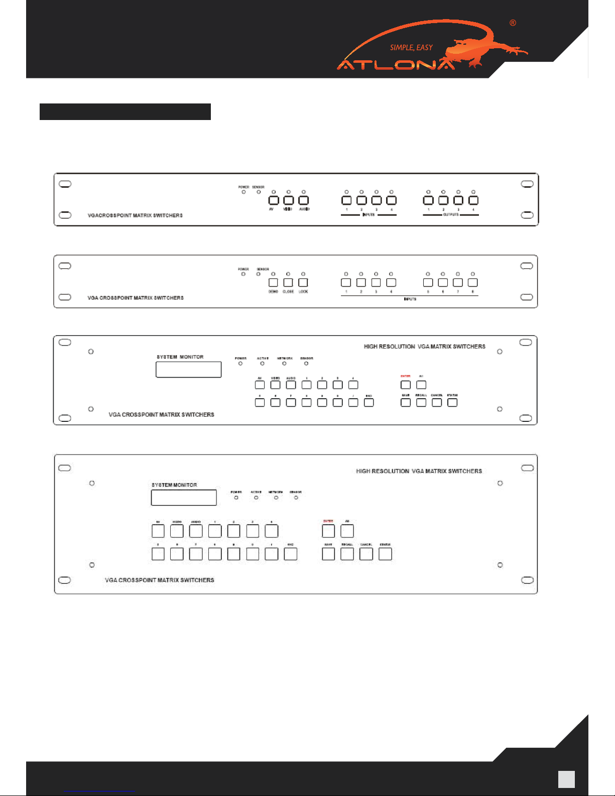
VIEW OF THE PRODUCT
4.1. Front View of Products
4.1.1. Front View of AT-VGA0404-A
4.1.2. Front View of AT-VGA0801
4.1.3. Front View of AT-VGA1601, AT-VGA3201
4.1.4. Front View of AT-VGA1604-A, AT-VGA1608-A
www.atlona.com | toll free: 1-877-536-3976
For International: 1-408-962-0515
5
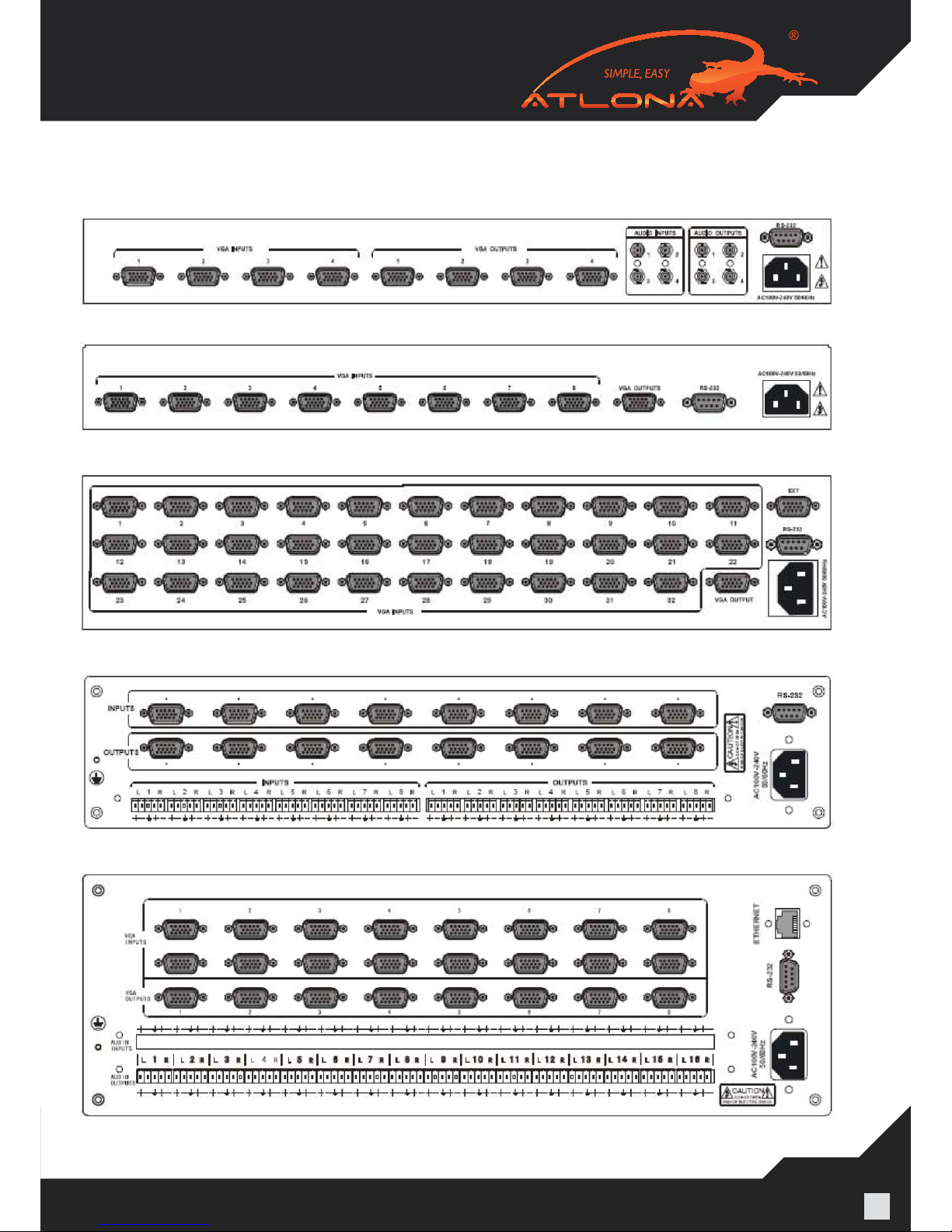
4.2. Rear View of Products
4.2.1. Rear View of AT-VGA0404-A
4.2.2. Rear View of AT-VGA0801
4.2.3. Rear View of AT-VGA1601, AT-VGA3201
4.2.5. Front View of AT-VGA1604-A, AT-VGA1608-A
4.2.4. Front View of AT-VGA0802-A, AT-VGA0804-A, AT-VGA0808-A
www.atlona.com | toll free: 1-877-536-3976
For International: 1-408-962-0515
6
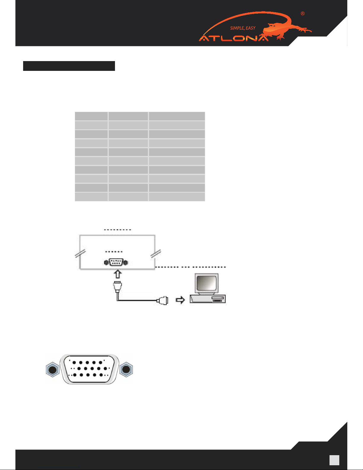
CONNECTING THE SWITCHER
The VGA matrix switchers connect using female 15-pin HD connectors for the video signal interface, and captive
screw connectors for the audio signal interface. The swticher has a front control panel, infrared remote controller
(Optional) and an Ethernet control (Optional), The VGA switcher can also be controlled via the RS-232 commu-
nication port. This RS-232 communication port is a female 9-pin D connector. The denition of its pins is shown
in the table below.
The switcher can also be controlled through COM1 or COM2 ports on a computer. To control the switcher, us-
ers may use the application SWITCHER 2.0 in the supplied CD or develop their own control software with the
protocol and control codes.
5.1. Connecting with input and output terminals
The VGA matrix switchers may take laptops, desktop computers, graphic workstations and document cameras
as their input signal source. Projectors, RP TVs, displays and ampliers can be connected on the output signal .
VGA Connection: The VGA matrix switchers support all kinds of the RGB and VGA signal sources with 15-PIN
HD VGA connectors.
Pin RS-232 Description
1 N/u Not used
2 Tx Transmit data
3 Rx Receive data
4 N/u Not used
5 GND Signal ground
6 N/u Not used
7 N/u Not used
8 N/u Not used
9 N/u Not used
www.atlona.com | toll free: 1-877-536-3976
For International: 1-408-962-0515
7
If the RGB source does not have VGA output terminals, please
convert the signals with an RGB to VGA
converter for getting high quality VGA output. Please use the
special VGA cable to connect the input and output devices.
Connect the 15-Pin HD connectors carefully.
Pin RGB YcbCr
1 R Cr
2 G Y
3 B Cb
4 Not used
5 Ground
6 R ground Cr ground
7 G ground Y ground
8 B ground Cb ground
9 Not used
10 Sync signal ground
11 Not used
12 Not used
13 H or H/V
14 V
15 Not used
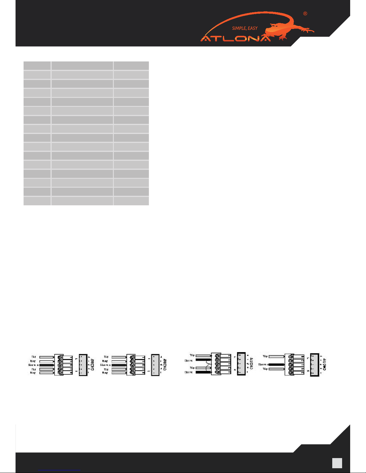
5.2. Audio signal connection
“AUDIO INPUTS”, “AUDIO OUTPUTS” audio network interface in RGB matrix switchers can be connected to the audio signal and amplify sources. The audio connection is more complicated than video. It has two types of connections:
balanced and unbalanced. The balanced connection transmits a pair of balanced signals with two cables. Because
interferences will have the same intensity and the opposite phases on the two cables; it will be counteracted in the
end. For the low frequency extent of the audio signal, it would be easily interfered under long distance transmissions.
Therefore as an anti-interference connection, it is mostly used in audio connections of special high end devices.
The unbalanced connection transmits signals with only one cable. Without counteraction, it can be interfered
more easily. Accordingly, it is adopted for household appliances or some cases with low technical demand.
Take the audio signal line for example: 1.Unbalanced: pin “G” connect to SLEEVE, pin “+” connect to TIP, pin
“–” connect to pin “G”; 2.Balanced: pin “G” connect to SLEEVE, pin “–” connect to RING, pin “+” Connect to TIP.
To select which connection is up to the interface of the device. When available, the balanced connection is the
rst choice. Before connection, please read the command or relevant demand in the user manual carefully. In
some cases, there is balanced in the source signal end but unbalanced in the destination end. If in a nonstandard
case, it is done to connect balanced for the balanced end and unbalanced.
Balanced Input Balanced Output Unbalanced Input Unbalanced Output
 Loading...