

Page 1
Installation Guide
AT-VCC-IR3-KIT
IP to IR Command Converter for Velocity Control System
AT-VCC-IR3-KIT
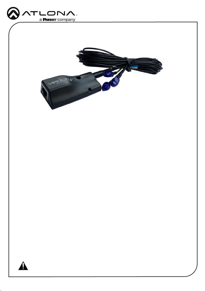
The Atlona AT-VCC-IR3-KIT is an accessory for the Atlona Velocity™ Control System that
provides conversion from IP control commands to IR. This Velocity Control Converter is very
compact and can be placed anywhere a device requires IR control. The VCC-IR3-KIT is remotely
powered through Power over Ethernet (PoE), or locally from a USB power source. The primary
unit installs onto any surface via a convenient mounting dock. A simple “click” locks it into place
for a secure, reliable installation. The IR adapter module includes three IR emitters attached by
a 3.5mm cable. Each emitter is independently addressable, allowing discrete IR control of three
dierent AV devices.
Package Contents
1 x AT-VCC
1 x AT-VCC-IR3
Operating Notes
• The AT-VCC-IR3-KIT is PoE, to power the unit, simply plug it into a PoE compatible network
switch. If the network switch is not PoE capable, a PoE injector (purchased separately) or USB
can be used.
• All devices (AT-VCC, Velocity, AT-VTP, switchers, etc) should be set to static IPs or the
DHCP IP address reserved for each individual device.
IMPORTANT: Velocity Gateway (AT-VGW-HW) must be set up before the AT-VCC-IR3-KIT
is fully functional.
1
Page 2
Panel Description
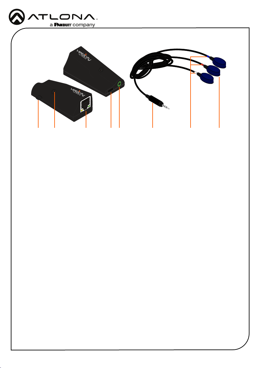
8 2 3 41 5 76
1 IR Window
Use to learn IR commands from a device’s
IR remote control.
2 Ethernet
Connect an Ethernet cable from this
port to the same network as the Velocity
Gateway.
3 USB
Can be used to power the VCC when PoE
is unavailable. Requires 5V DC @ 250mA
(not supplied).
4 3.5mm Port
Connect the included VCC-IR3 into this
port.
5 3.5mm Connector
Connect the 3.5mm connector to the
3.5mm port of the VCC.
6 3 x IR Emitters
Connect the 3.5mm connector to the
3.5mm port
7 IR Bands
Colored bands provide a way to
dierentiate which emitter goes to which
control signal. White is control port 1, red
is control port 2, and blue is control port
3.
8 Factory Reset Button
Press and hold this button to reset all
settings to the factory default.
Installation Guide
AT-VCC-IR3-KIT
IP
The AT-VCC is set to DHCP by default. If the network does not support DHCP, it will
automatically set the AT-VCC to the static IP of 192.168.1.70 after 30 seconds.
VHelp and webGUI
Velocity will nd the VCC when scan network is used, but if the VCC needs to be set up o site
rst, the software VHelp can be used.
1 Connect the IR three emitter cable into the 3.5mm port on the unit.
2 Connect the AT-VCC to a network switch (PoE is best if a PoE switch is not available, a
power injector or mini USB to USB cable may be used).
3 Download VHelp from the resource tab of https://atlona.com/product/AT-VCC-IR3-KIT.
4 Unzip the le to the local PC
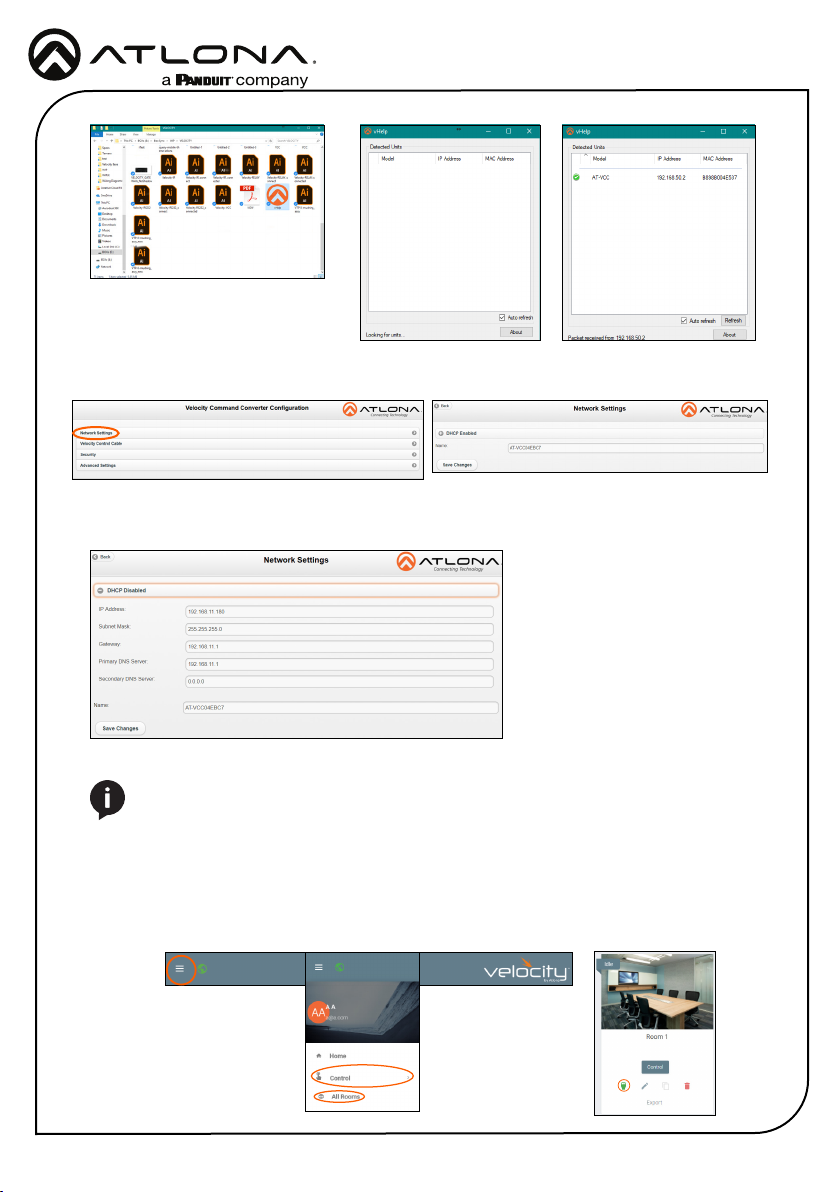
5 Double-click the VHelp executable to open the program. Vhelp will start discovery as soon
as the program is opened.
2
Page 3
Installation Guide
AT-VCC-IR3-KIT
6 Double click on the VCC (to determine the correct one, look on the bottom of the VCC for
the MAC address). The PC default browser will open to the AT-VCC webGUI.
7 Select Network Settings to open the IP conguration page.
8 Select the DHCP Enabled header, this will disable DHCP and allows IP settings to be edited.
9 Type in the IP details to
match the network details
of the Gateway. e.g. If the
Velocity gateway is located at
the IP of 192.168.12.15, then
the VCC should be set to an
IP within the 192.168.12.XXX
range that has not already
been used.
10 Press the Save Changes button.
NOTE: Connecting the VCC to Velocity can only be done once Velocity has been set
up. View the Velocity Manual for instructions.
11 Open any browser on the network and type in the IP address of Velocity.
12 Log in and select the ≡ button from the top left corner and select Control.
13 More options will appear. Select All Rooms. A new screen will open.
14 Select the Edit Room Technology button on the room tile. The Modify Technology screen will
open.
3
Page 4
Installation Guide
AT-VCC-IR3-KIT
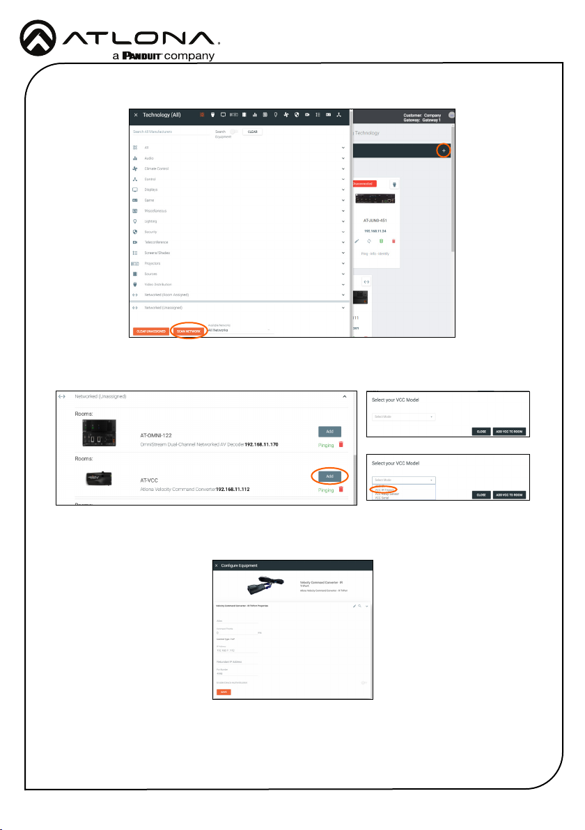
15 Select the + button located at the top right corner of the room. A new menu will open.
16 Press the scan network button. All Atlona devices found will appear in the unassigned list.
17 Select the Add button next to the VCC. A new pop up will appear.
18 Select the VCC IR Triport (based on device/function) from the drop down menu.
19 Press the ADD VCC TO ROOM button. A VCC tile will appear in the room.
4
Page 5
Installation Guide
AT-VCC-IR3-KIT
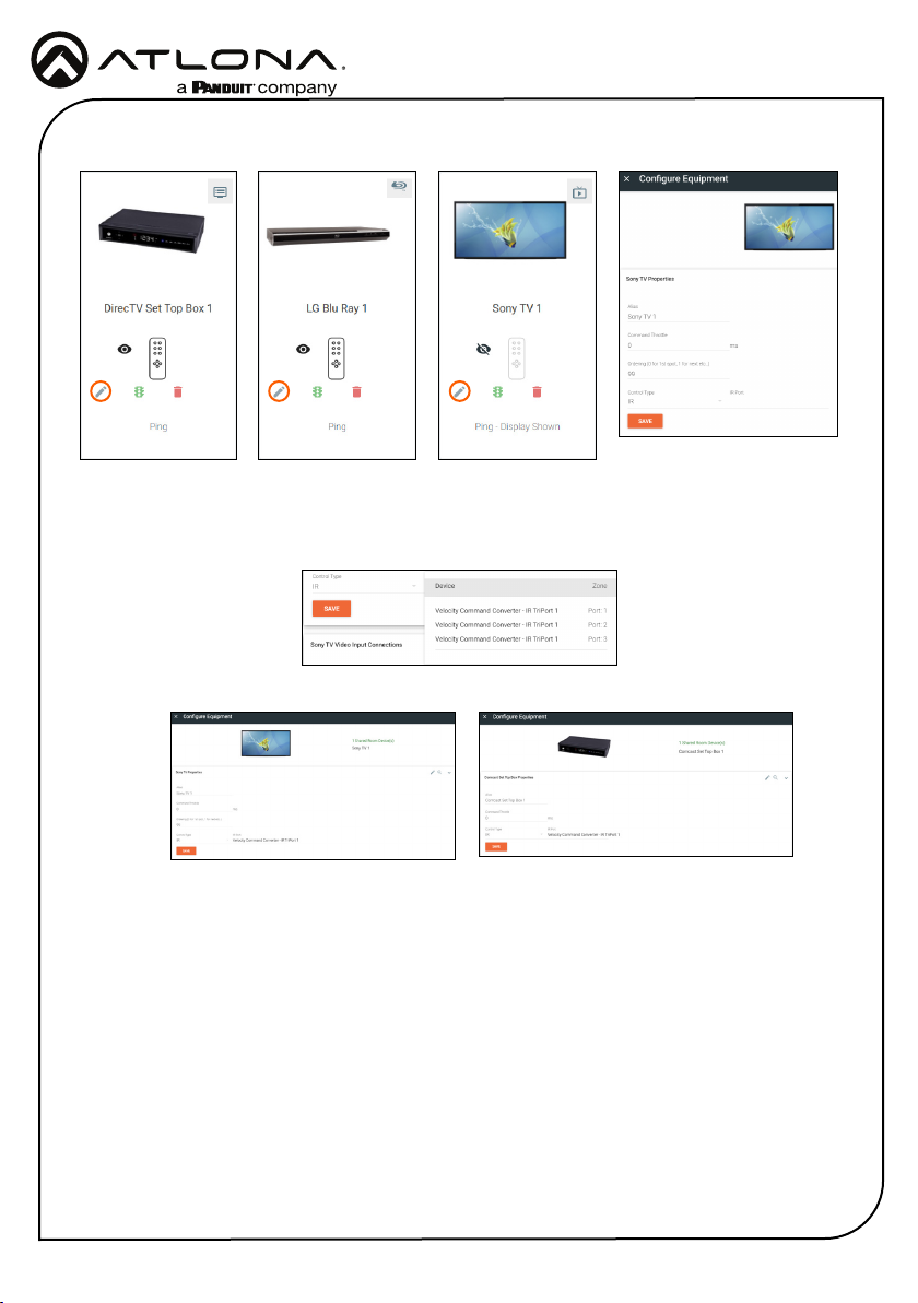
20 Select edit on the controlled device’s tile. A new window will slide open.
21 *Optional* If the device has multiple Control Types, select IR from the Control Type drop
down menu.
22 Select the VCC from the IR Port drop down menu.
23 *Optional* Repeat for up to three devices when using the VCC triport.
The VCC is ready to use and will pass any commands triggered from the control screen.
5
Page 6
Installation Guide
AT-VCC-IR3-KIT
IR Learning
The VCC IR has the ability to learn IR codes from a device’s IR remote. Create equipment with
IR control easier and without manually entering a list of IR command using the IR remote control
with the VCC IR.
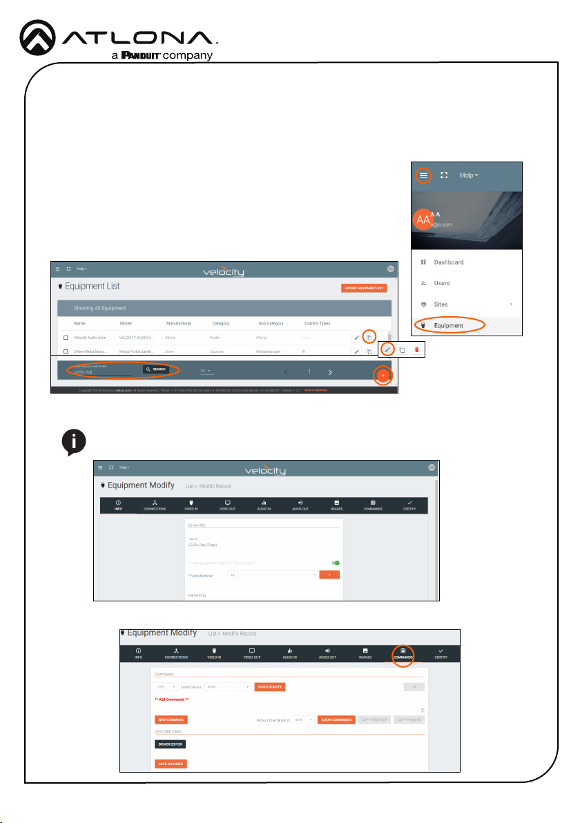
1 Open the Equipment List using the left = navigation. A new screen
will open.
2 Create a device to be added to the room. A new screen will open.
a Select the + button at the bottom of the page to create a new
device.
b Search for and duplicate an existing similar driver to be edited.
3 Fill in the device information (e.g. Name, manufacturer, etc).
NOTE: If creating a new device the other tabs will need to be lled. Follow the
directions within the Equipment section of the Velocity manual.
=
4 Select the commands tab from the top navigation.
6
Page 7
Installation Guide
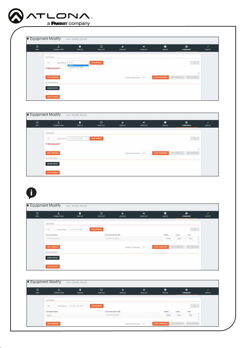
5 Select the IP of the VCC IR from the Learn Device drop down menu.
6 Press the NEW COMMAND button. A new line will appear above the button.
NOTE: If a device was duplicated, remove all the previous commands using the
delete link.
AT-VCC-IR3-KIT
7 Fill in the command name of the button to be learned.
7
Page 8
Installation Guide
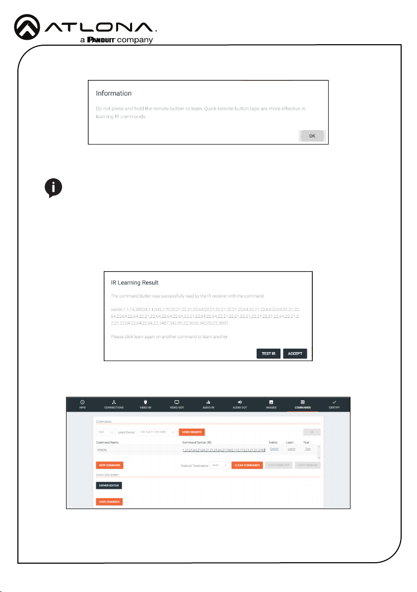
8 Select the learn link. An information pop up will appear. Press OK.
9 Point the device’s IR remote at the IR learn window located halfway down the VCC and
press the button to be learned.
NOTE: Use quick button presses to learn, do not hold the button down.
10 When the command is successfully learned, a pop up will appear with the learned IR
command.
a Press ACCEPT to return to the commands.
b If there is an IR Emitter connected, press TEST IR to broadcast the command to the
device to verify the command works. Press ACCEPT once done testing.
AT-VCC-IR3-KIT
11 The command will appear in the Command Syntax eld. Repeat the IR learn process until all
needed commands are learned.
12 Press the save changes button.
8
Page 9
Installation Guide
AT-VCC-IR3-KIT
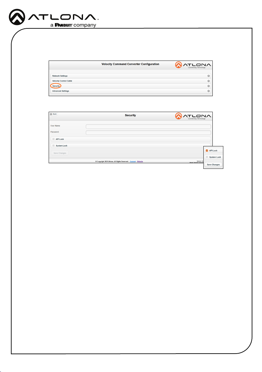
Security
Security options have been provided with the VCCs, to set between web UI, API, and system
lock.
• Select Security from web UI menu. A new page will open.
• To protect the web UI from being altered, a username and password can be set, once a
username and password has been set, select the Save Changes button to enable login.
• To lock the conguration of the VCC, select API lock (after setting a username and
password) and press the Save Changes button. With the API lock set, no conguration
changes can be made through TCP commands and must be changed through the web
UI.
• System Lock should not be used unless all conguration and routing has been set
and will not need to be changed. Once System Lock has been selected and the Save
Changes button pressed, no device changes can be made unless the unit is factory reset
through the button on the side of the VCC.
9
Page 10
Installation Guide
AT-VCC-IR3-KIT
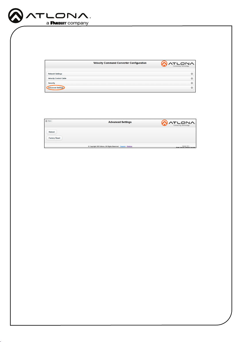
Advanced Settings
If needed, the system can be rebooted or reset from the Advanced Settings page. Select it from
the home page menu.
• Reboot - Use this button to restart the unit.
• Factory Reset - Use this to set everything back to default settings. This will reset the unit
to DHCP, which may cause the IP to change and the unit to need to be rediscovered.
10
Page 11
Installation Guide
AT-VCC-IR3-KIT
Firmware Update
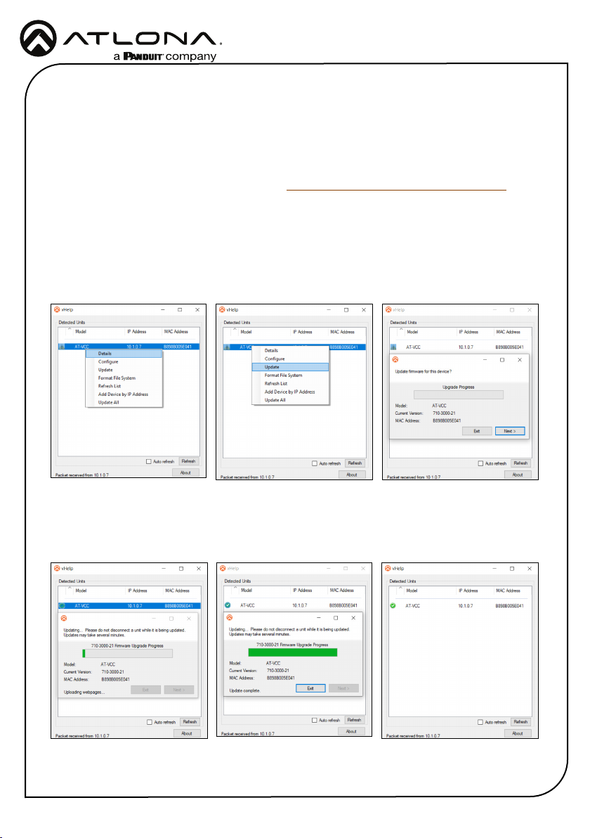
To update the VCC the most recent vHelp software will be needed. The vHelp has the rmware
built into the software and will automatically detect if the VCC is on the most recent rmware.
1 Connect the AT-VCC to a network switch (PoE is best if a PoE switch is not available, a
power injector or mini USB to USB cable may be used).
2 Download VHelp from the resource tab of https://atlona.com/product/AT-VCC-IR3-KIT.
3 Unzip the le to the local PC
4 Double-click the VHelp executable to open the program. Vhelp will start discovery as soon
as the program is opened.
5 Once the unit is found, if it is out of date an exclamation mark will display next to it. Right
click to open the drop down menu.
6 Select Update from the drop down list. A new pop up will appear.
7 Press the Next button to start the update. The progress bar will cycle through green. This
process can take up to 2 minutes.
8 Once the update is complete, press Exit. The unit will now show a green check mark next to
it to show the unit is up to date.
11
Page 12
Installation Guide
AT-VCC-IR3-KIT
Warranty
To view the product warranty, use the following link or QR code:
https://atlona.com/warranty/.
English Declaration of Conformity
The English version can be found under the resources tab at:
https://atlona.com/product/at-vcc-ir3-kit/.
Chinese Declaration of Conformity 中国RoHS合格声明
由SKU列出於:
https://atlona.com/about-us/china-rohs/.
Version 6
atlona.com • 408.962.0515 • 41.43.508.4321
US International
© 2022 Atlona Inc. All rights reserved. “Atlona” and the Atlona logo are registered trademarks of Atlona Inc. All other brand names and trademarks or registered
trademarks are the property of their respective owners. Pricing, specications and availability subject to change without notice. Actual products, product images, and
online product images may vary from images shown here.
12
 Loading...