

Installation Guide
AT-USB-EX100-KIT
HDBaseT Extender Kit for USB 2.0
AT-USB-EX100-KIT
The Atlona AT-USB-EX100-KIT is a long-distance extender kit for high speed USB signals. It
supports transmission of USB 2.0 data up to 330 feet (100 meters) using a single, cost eective
Category-type twisted pair cable. The AT-USB-EX100-KIT is ideal for popular conferencing
applications such as Zoom® and Microsoft® Teams®, where USB components including
laptops, cameras, microphones, and speakers are located in dierent areas of the room. The kit
is also suitable in classrooms for routing USB between an interactive display or projector, and
the instructor’s laptop. The AT-USB-EX100-KIT includes both transmitter and receiver endpoints.
Compact enclosures and included brackets allow the devices to be discretely mounted near
computers and USB peripherals. The AT-USB-EX100-KIT is a great solution for connecting USB
components separated by distances not supported by traditional cabling.
Package Contents
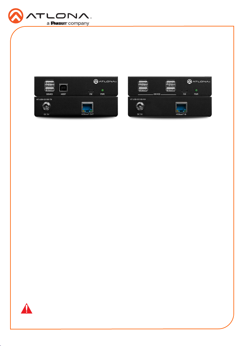
1 x AT-USB-EX100-TX
1 x AT-USB-EX100-RX
2 x 5 V / 4 A Power Supplies
2 x Mounting Plates
4 x Mounting Screws
1 x Installation Guide
IMPORTANT: Visit http://www.atlona.com/product/AT-USB-EX100-KIT for the latest
rmware updates and User Manual.
1
AT-USB-EX100-RX
DC 5V HDBaseT IN
AT-USB-EX100-TX
DC 5V HDBaseT OUT
FW PWR
AT-USB-EX100-RX
DC 5V HDBaseT IN
DEVICE
AT-USB-EX100-TX
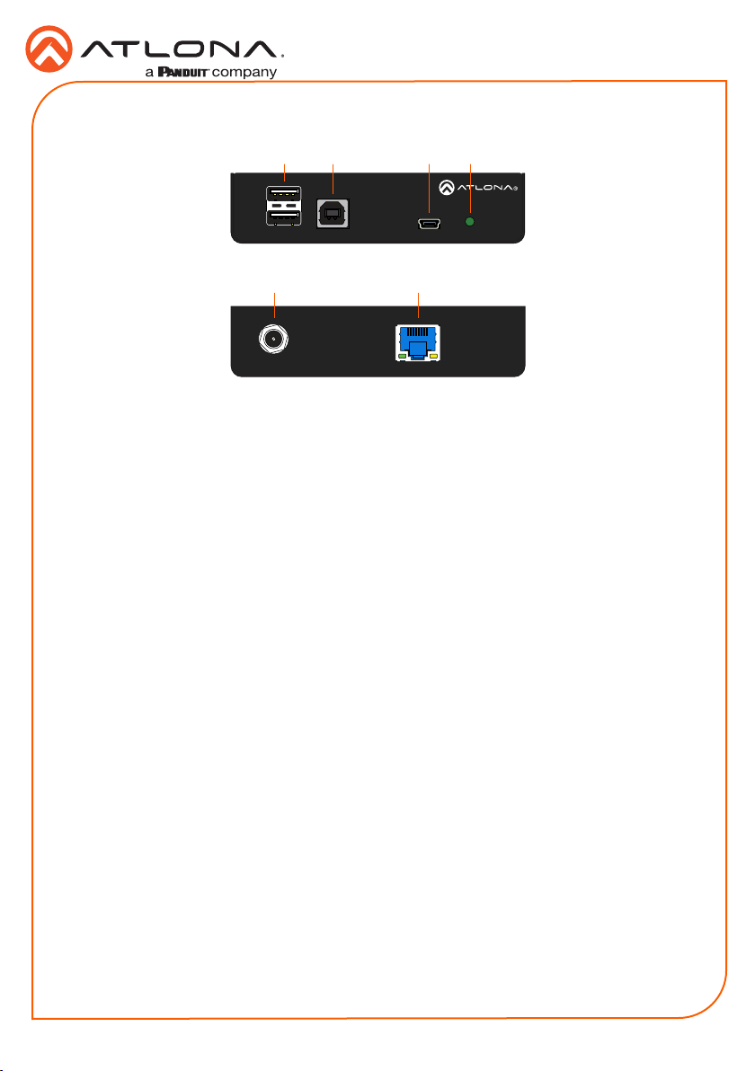
1 DEVICE
Connect up to two USB devices (e.g. mouse, keyboard, etc.) to these ports. These ports
provide 2.5 W per USB device interface.
2 HOST
Connect a USB cable from this port to the host computer.
3 FW
Connect a mini USB-to-USB cable from this port, to a computer, to update the rmware.
4 PWR
The PWR LED indicator will glow green when the AT-USB-EX100-TX is powered.
5 DC 5V
Connect the included 5 V DC power supply to this power receptacle.
6 HDBaseT OUT
Connect a category cable from this port to the HDBaseT IN port of the AT-USB-EX100-RX.
2
1 3 4
Front
5 6
DC 5V HDBaseT OUT
Rear
Installation Guide
AT-USB-EX100-KIT
FW PWRHOSTDEVICE
AT-USB-EX100-TX
2
AT-USB-EX100-RX
DC 5V HDBaseT IN
AT-USB-EX100-RX
Installation Guide
AT-USB-EX100-KIT
1 2 3
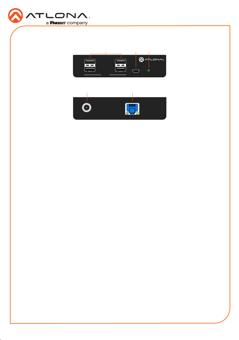
1 DEVICE
Connect up to four USB devices (e.g. mouse, keyboard, etc.) to these ports. These ports
provide 2.5 W per USB device interface.
2 FW
Connect a mini USB-to-USB cable from this port, to a computer, to update the rmware.
3 PWR
The PWR LED indicator will glow green when the AT-USB-EX100-RX is powered.
4 DC 5V
Connect the included 5 V DC power supply to this power receptacle.
5 HDBaseT OUT
Connect a category cable from this port to the HDBaseT IN port of the AT-USB-EX100-TX.
DEVICE
Front
4 5
DC 5V HDBaseT IN
Rear
FW PWR
AT-USB-EX100-RX
3
Installation Guide
AT-USB-EX100-RX
DC 5V HDBaseT IN
AT-USB-EX100-TX
DC 5V HDBaseT OUT
FW PWR
AT-USB-EX100-RX
DC 5V HDBaseT IN
DEVICE
AT-USB-EX100-RX
DC 5V HDBaseT IN
AT-USB-EX100-KIT
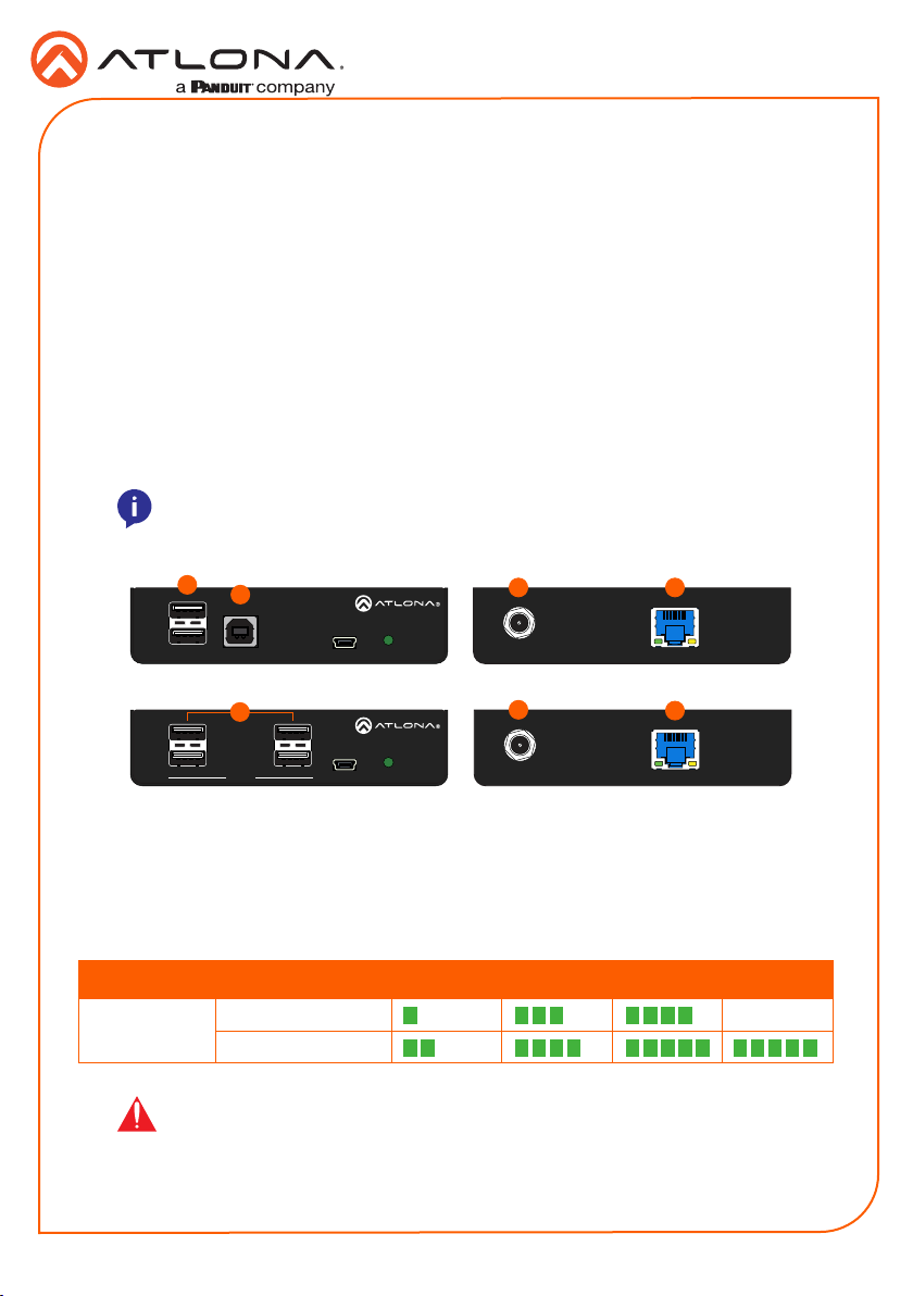
Installation
1. Connect up to two USB devices (speakerphone, etc.) to the DEVICE ports on the AT-USB-
EX100-TX. These ports provide 2.5 W per USB device interface.
2. Connect a USB cable from the host device to the HOST port on the AT-USB-EX100-TX.
3. Connect up to four USB devices (mouse, keyboard, etc.) to the DEVICE ports on the AT-
USB-EX100-RX. These ports provide 2.5 W per USB device interface.
4. Connect a category cable (CAT5e or better), from the HDBaseT OUT port on the AT-USB-
EX100-TX, to the HDBaseT IN port on the AT-USB-EX100-RX. Maximum cable length
should not exceed 330 feet (100 meters).
5. Connect the included 5 V DC power supplies to both the AT-USB-EX100-TX and AT-USB-
EX100-RX to the DC 5V power receptacles.
6. Connect both power supplies to available AC outlets.
NOTE: This product is not a PoE device. The included power supplies must
be connected to both the AT-USB-EX100-TX and AT-USB-EX100-RX.
1
2
3
DEVICE
FW PWRHOSTDEVICE
FW PWR
DC 5V HDBaseT OUT
5
DC 5V HDBaseT IN
45
4
AT-USB-EX100-TX
AT-USB-EX100-RX
Cable Recommendation Guidelines
Refer to the tables below for recommended cabling when using Altona products with HDBaseT.
The green bars indicate the signal quality when using each type of cable. Higher-quality signals
are represented by more bars.
Core Shielding CAT5e CAT 6 CAT6a CAT 7
Solid UTP (unshielded) N/A
STP (shielded)
IMPORTANT: Stranded or patch cables are not recommended due to
performance issues.
4
 Loading...