

Atlona AT-UHD-SW-51 User Manual
atlona.com
Toll free: 1-877-536-3976
Local: 1-408-962-0515
4K/UHD 5 Input HDMI Switcher
Please check http://www.atlona.com/UHD-SW-51.html
for the most recent firmware update or manual.
User Manual
AT-UHD-SW-51

2
atlona.com
Toll free: 1-877-536-3976
Local: 1-408-962-0515
Table of Contents
1. Introduction ................................................................................................... 3
2. Package Contents ................................................................................................... 3
3. Features ................................................................................................... 3
4. Panel Descriptions
a. Front ................................................................................................... 4
b. Back ................................................................................................... 4
5. Infrared Remote Control ................................................................................................... 4
6. ARC ................................................................................................... 5
7. Captive Screw ................................................................................................... 5
8. WebGUI ................................................................................................... 6-11
9. RS-232 ................................................................................................... 12-14
10. Installation Diagram ................................................................................................... 15
11. Specifications ................................................................................................... 16
12. Safety Information ................................................................................................... 17
13. Warranty ................................................................................................... 18-19
14. Registration ................................................................................................... 19

3
atlona.com
Toll free: 1-877-536-3976
Local: 1-408-962-0515
• 1 x UHD-SW-51
• 1 x 5V DC power supply
• 2 x Female captive screw connector (3 pin: RS-232, 2 pin: power)
• 1 x Remote control
• 1 x User Manual
• Five HDMI inputs
• Smart switching with auto-detect (5V detect) for inputs (activated through RS-232 or TCP/IP)
• HDMI Audio Return Channel compatible
• HDCP management
• Supports 4K pass through @ 60Hz 4:2:0 chroma sub-sampling
• Supports Dolby® TrueHD and DTS-HD Master Audio™ pass-through ability when using an HDMI cable
• Digital audio de-embedding through the S/PDIF output for up to DTS 5.1™ and Dolby® Digital
• Two channel PCM and LPCM de-embedding through analog output
• EDID management
• Easy to use webGUI through TCP/IP connection
• Half-rack size with optional rack mount ears
Introduction
Features
Package Content
The 4K/UHD 5 input HDMI switcher is an affordable 5-input, 1-output switcher with 4K pass-through, IR,
RS-232, and TCP/IP control, EDID and HDCP management, and ARC. The UHD-SW-51 provides an easy to
install solution for home and small offices.
4
atlona.com
Toll free: 1-877-536-3976
Local: 1-408-962-0515
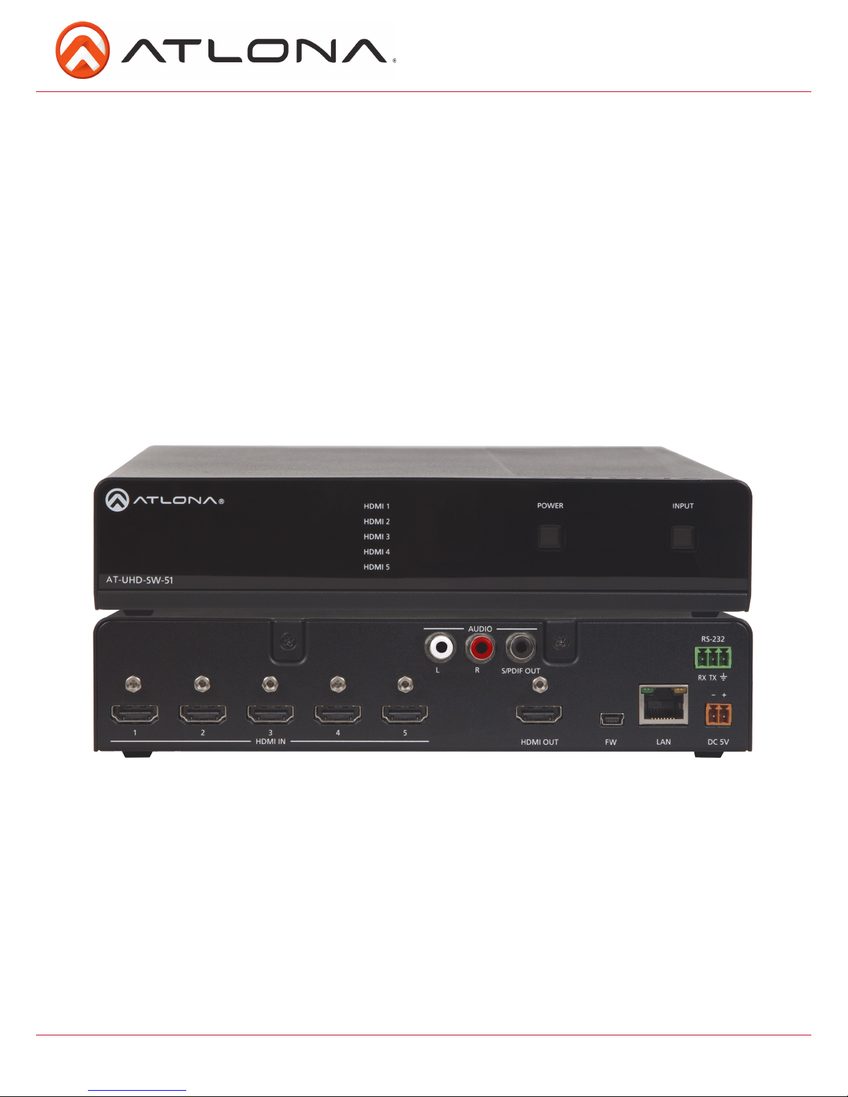
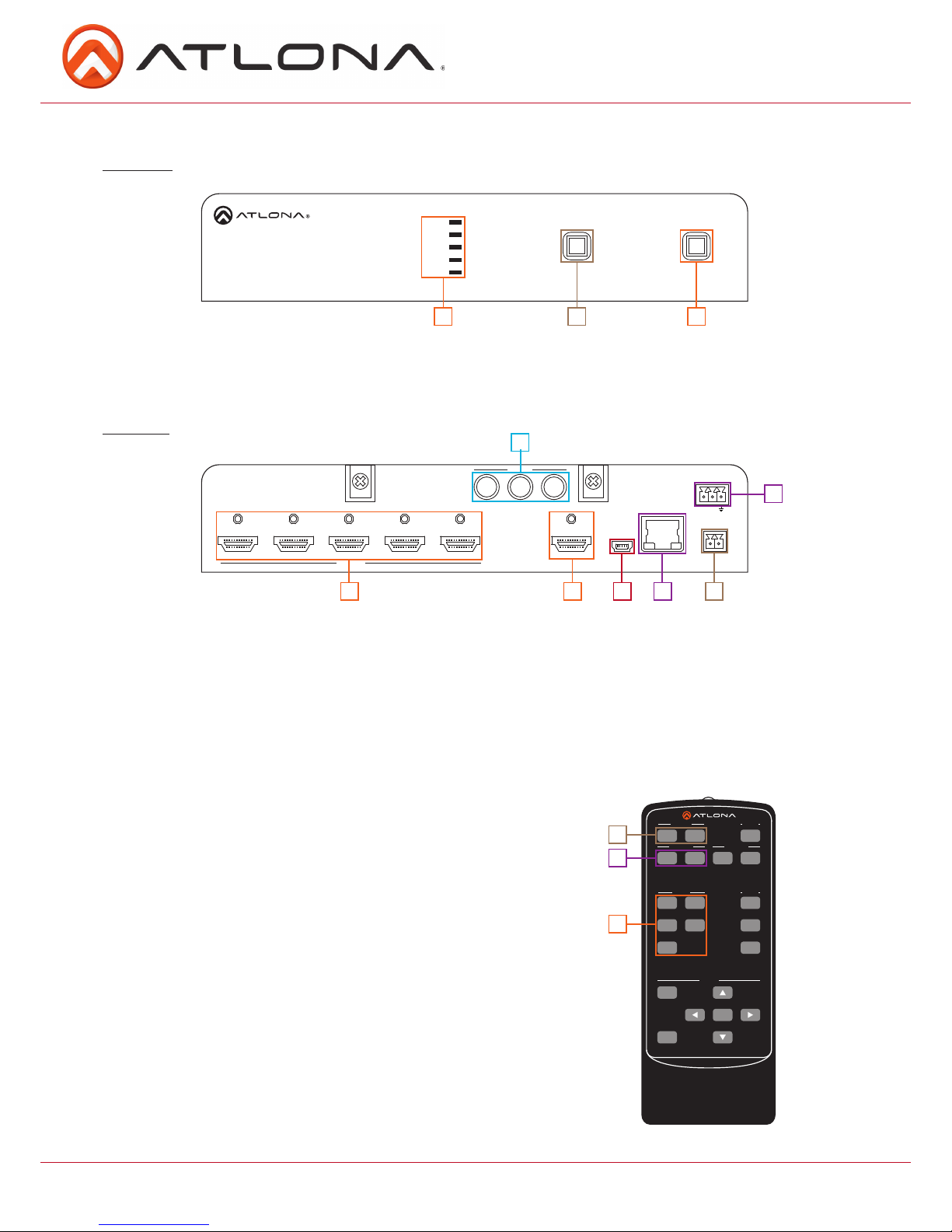
Back Panel
1. HDMI IN - Connect sources here
2. HDMI OUT - Connect to an HDMI display, extender, or switcher
3. Mini USB port: Firmware update port, connect a Mini USB to USB A cable to a computer
4. LAN port - Connect network switch or router to this port for TCP/IP or webGUI control
5. DC 5V: Connect included locking, 5V DC power supply here
6. RS-232 port - Connect control system to RS-232 port
7. Audio output - Connect to an amplifier, audio receiver, or other audio device
1
1
2
2
1
2
3
5
3
3 4
6
7
Panel Descriptions
Front Panel
1. HDMI LEDs - Illuminates to indicate the selected source
2. Power Button - Turns switcher on or places it in standby mode
3. Input Button - Switches between HDMI inputs
HDMI 1
HDMI 2
HDMI 3
HDMI 4
HDMI 5
AT-UHD-SW-52
POWER
INPUT
HDMI 1
HDMI 2
HDMI 3
HDMI 4
HDMI 5
AT-UHD-SW-52
R
L
FW LAN
RS-232
RX TX
DC 5V
-
+
HDMI IN
HDMI OUT
AUDIO
S/PDIF OUT
1 2 3 4 5
POWER
INPUT
Remote Control
1. Power On/Off: Turn switcher power on and off
2. Video On/Off: Turns HDMI video off
3. Input selection: Selects source
Note: On/off video 2, audio, and setup buttons are not functional for the
UHD-SW-51 switcher
SW-R1
Setup
Video 1
Video
Video 2
All On
Power
Vol +
Vol
-
Menu
Return
Enter
Mute
1
324
5
Input
Audio
On
Off
On
Off
On
Off
5
atlona.com
Toll free: 1-877-536-3976
Local: 1-408-962-0515
Captive Screw
HDMI 1
HDMI 2
HDMI 3
HDMI 4
HDMI 5
AT-UHD-SW-52
R
L
FW LAN
RS-232
RX TX
DC 5V
-
+
HDMI IN
HDMI OUT
AUDIO
S/PDIF OUT
1 2 3 4 5
POWER
INPUT
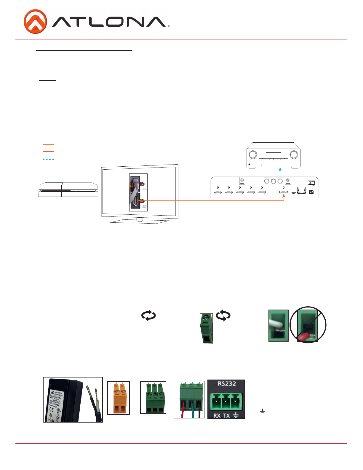
ARC enables a source connected to a display to route audio back to the switcher and send the de-embedded
audio out the S/PDIF output.
1. Check to be sure the display supports ARC
2. Enable ARC on the HDMI output of the switcher through RS-232 (command ARC on), TCP/IP, or webGUI
3. Connect the HDMI output port of the switcher to the ARC labeled input port on the display
NOTE: The switcher must be connected to the display’s HDMI ARC input
Note: Works well with audio from ARC enabled “Smart” televisions
4. Connect the source to a non ARC HDMI input port on the display
5. Connect the S/PDIF port to an AVR or Zone Amp
Audio Return Channel (ARC)
Steps
HDMI
Bidirectional HDMI w/ARC signal
Audio loop-out
S/PDIF audio loop-out
Bidirectional HDMI ARC signal
HDMI
Game Console
Connecting
Captive screw connectors are an added feature on the UHD-SW. The Captive screw connectors allow you to
cut cables down to a suitable length, reducing cable clutter while providing a more reliable connection.
The captive screw connectors have
a contact bar that is adjusted to
compress the wire against the top
contact plate. Use the screws at the
top of the connector to compress the
wire against the contact plate.
When connecting the cables to the female captive screw connector it is important that the wires be
terminated correctly. The female captive screw connector has a contact plate at the top and must have the
wires touching it for signal to pass. When wired correctly (see picture A) the signal will pass, incorrectly (see
picture B) no signal will pass.
The power cable (picture 1) will have exposed wires. Each wire is encased in a different colored cover. Female
captive screw connectors are included: Power (see picture 2) and RS-232 (see picture 3).
2
Power
RS-232
Clockwise
Counter
Clockwise
Turn the screws clockwise to
raise the contact bar to the
upper contact plate and hold
the wires in place.
Turn the screws counter
clockwise to lower the
contact bar to release the
wires.
A
B
3
RS-232 pin out will be
determined by the RS-232
cable and will connect as Rx
(receiver), Tx (transmitter),
and (ground). (See picture 4)
Pin out color
will differ per
RS-232 cable.
4
Black: - White: +
- +
1
6
atlona.com
Toll free: 1-877-536-3976
Local: 1-408-962-0515
TCP/IP
For convenience, the UHD-SW comes with DHCP on. This enables the switcher to be connected
to a network without knowing available IP addresses. If your network does not allow dynamic IP
addresses or if you are using the UHD-SW with a TCP/IP control system, this feature may be turned
off and the IP address set using RS-232 commands or the webGUI.
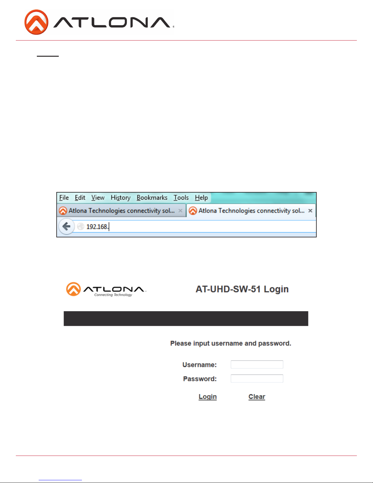
TCP/IP WebGUI
Atlona has created an easy to use WebGUI for initial setup and later changes to the configuration
of the UHD-SW.
To begin, plug a LAN cable into the LAN port of the UHD-SW and your network, then type the IP
address of the UHD-SW into a web browser of a PC connected to the same network (as seen below).
To find the switcher IP: use RS-232 command “IPCFG”.
Important: If any stability issues are experienced, disable any anti-virus or firewall that may interfere with
network communication to the switcher. Once set up is done and the switcher GUI is no
longer used, the firewall and anti-virus can be re-enabled.
A login screen will appear (this is the same log in for admin and general users). For the first log in
(and future admin changes) the username is “root” and password is “Atlona”.
Note: Only the admin password can be changed (see page 9). The username will always remain
“root”.
Note: IP addresses may also be found using common free IP scanner software such as “Advanced IP
Scanner”
 Loading...