

Atlona AT-UHD-CLSO-612ED User Manual
Atlona 6 Input Switcher and
Scaler with HDBaseT and
Mirrored HDMI Output
AT-UHD-CLSO-612ED
User Manual
Please check http://www.atlona.
com/product/AT-UHD-CLSO-
612ED for the most recent
firmware update or manual.
atlona.com
Toll free: 1-877-536-3976
Local: 1-408-962-0515

Table of Contents
1. Introduction .......................................................................................... 3
2. Package Contents .......................................................................................... 3
3. Features .......................................................................................... 3
4. Panel Descriptions
a. Front Panel .......................................................................................... 4
b. Rear Panel .......................................................................................... 5
5. Wall/Rack Mounts .......................................................................................... 5
6. Category Cable .......................................................................................... 6
7. Analog Multi-Format Inputs .......................................................................................... 7
8. Audio Connections .......................................................................................... 8
9. Microphone .......................................................................................... 9
10. On Screen Display .......................................................................................... 10-12
11. TCP/IP and GUI .......................................................................................... 13-25
12. IR .......................................................................................... 26
13. RS-232
a. Connection .......................................................................................... 27
b. Set Up .......................................................................................... 27
c. Commands .......................................................................................... 28-31
d. IP Commands .......................................................................................... 31
e. Baud Rate .......................................................................................... 32
14. Connection Diagram .......................................................................................... 33
15. Control Drivers .......................................................................................... 33
16. CLSO-612 Updating .......................................................................................... 33
17. Specifications .......................................................................................... 34
18. Safety .......................................................................................... 35
19. Warranty .......................................................................................... 36-37
20. Registration .......................................................................................... 37
atlona.com
2
Toll free: 1-877-536-3976
Local: 1-408-962-0515

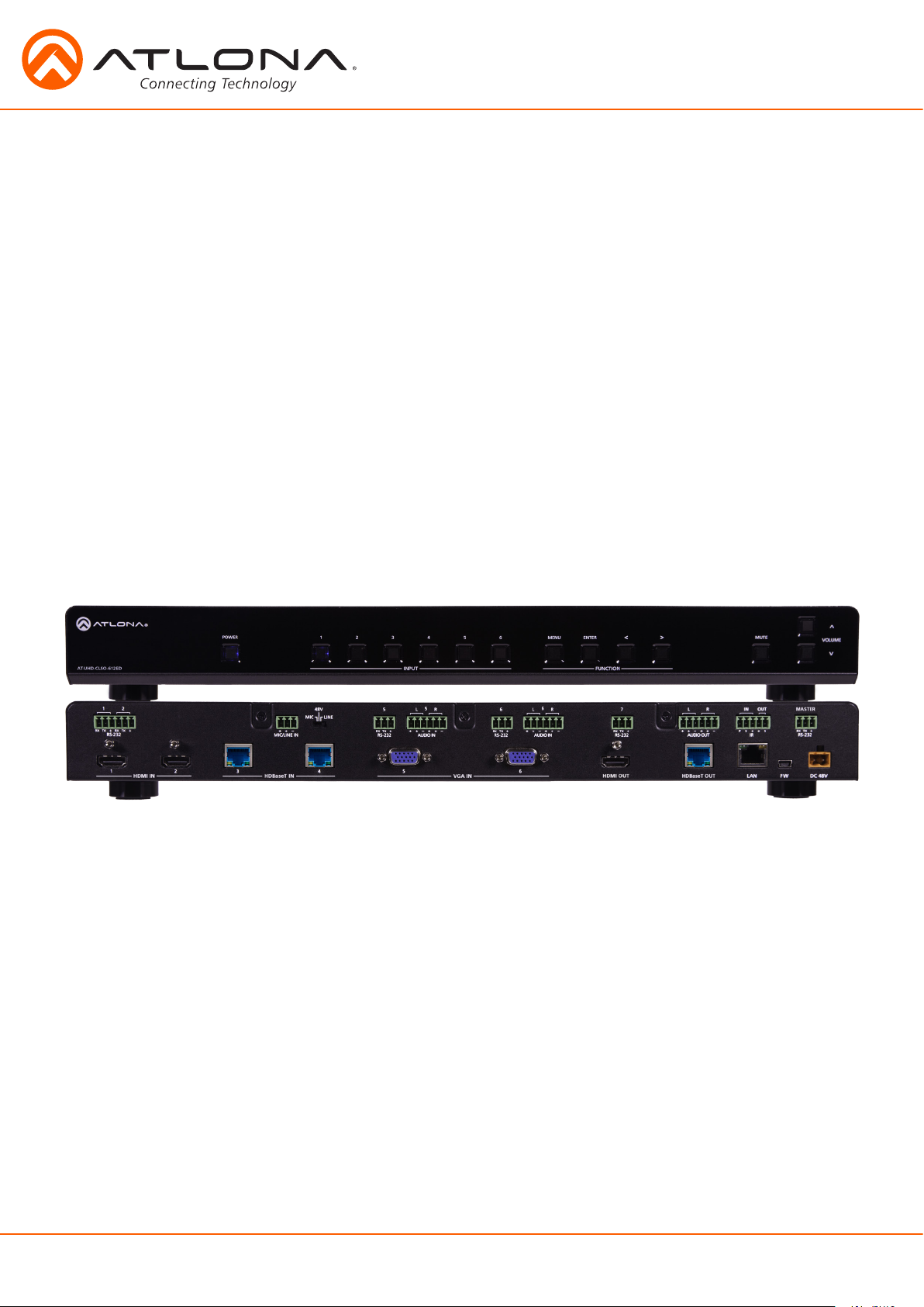
Introduction
The Atlona AT-UHD-CLSO-612ED is an advanced six-input, multi-format switcher with 4K scaling,
Ethernet-enabled HDBaseT™, and PoE capabilities. It simplifies classroom and small office system
integration by providing two HDBaseT inputs, two HDMI inputs, two multi-function analog inputs,
plus mirrored HDBaseT and HDMI outputs. Advanced Automatic System Control (AASC) features
on the switcher provide automatic display control and automatic input selection. An internal
Ethernet hub in on the switcher enables control signal pass-through and network distribution. The
AT-UHD-CLSO-612ED contains a full RS-232 signal distribution system to route control signals to
local sources and displays. Professional audio features such as a microphone input with 48-volt
phantom power and ducking eliminates additional voice-lift audio needs. The switcher is configured
and managed by Atlona Management System software to reduce installation time and enable
remote support. The AT-UHD-CLSO-612ED addresses a wide array of AV switching and processing
needs often encountered in classrooms, conference rooms, boardrooms, training rooms and other
presentation settings.
Package Contents
• 1 x AT-UHD-CLSO-612ED
• 11 x Female captive screw connector
6 pin: audio, 5 pin: IR, 3 pin: RS-232, 3 pin: MIC/Line
• 1 x 48V/3.125A DC power supply adaptor
• 1 x Pair of dual purpose wall/rack mounts
• 1 x IR remote control
• 1 x User manual
Features
• Accepts HDMI and HDBaseT inputs from up to 328 feet away
• Multifunctional VGA ports for RGBHV, component, S-Video, and composite signals
• Microphone (dynamic, phantom, and line) input with ducking
• HDBaseT output mirrored to HDMI output
• Automatic display control
• Auto switching - automated switching to last connected source without using a control system
• Balanced audio inputs for embedding audio
• Balanced (+4 dbu) analog audio output for de-embedding audio to amplifiers or audio systems
• Upscaling and downscaling to ensure compatibility with any display or source up to 4K resolution
• Control via RS-232, IR, TCP/IP, WebGUI, and multi-language On-Screen Display
• Master and sub volume control
• Adjust treble and bass on audio output to ensure the best speaker performance
• PoE to HDBaseT inputs and outputs (no power required with compatible devices)
• HDCP Compliant with management for non-compliant HDCP sinks
• Supports 3D pass-through
atlona.com
3
Toll free: 1-877-536-3976
Local: 1-408-962-0515
Panel Description
AT-UHD-CLSO-612ED
POWER 1 2 3 4 5 6 ENTER MUTE
VOLUME
>
<
<
<
MENU
INPUT FUNCTION
Front Panel
<
VOLUME
<
AT-UHD-CLSO-612ED
POWER
5
1
2
4
3
INPUT
6
MENU
ENTER
FUNCTION
<
MUTE
>
1 2 3 4 5 6 7
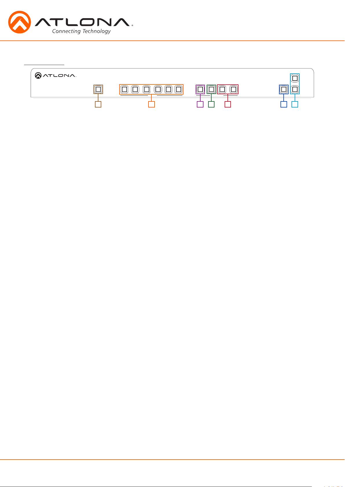
1. Power: Use to turn the unit on, place into standby, or turn the display on/off. LED will illuminate
blue for on and red for standby
2. Input: Switch between inputs - current input is blue
1 - HDMI input 1 - Used while updating MCU firmware
2 - HDMI input 2 - Used while updating OSD firmware
3 - HDBaseT input 1 - Used while updating DSP firmware
4 - HDBaseT input 2 - Used while updating FPGA firmware
5 - Multifunction analog input 1
6 - Multifunction analog input 2
3. Menu: Access the OSD menu - also used as a back button within the OSD
4. Enter: Select options within the OSD menu
5. < and >: Changes values of the currently select option (e.g. contrast to 50)
6. Mute: Silences all audio output from the CLSO-612ED and (when programmed - see pages 21-23)
mutes the display
^
7. Volume ^/ : Used to adjust volume (CLSO or Display) and navigate the OSD menu
atlona.com
4
Toll free: 1-877-536-3976
Local: 1-408-962-0515

AT-UHD-CLSO-612ED
POWER 1 2 3 4 5 6 ENTER MUTE
VOLUME
>
<
<
<
MENU
INPUT FUNCTION
INPUT
AT-UHD-CLSO-612ED
FUNCTION
5
6
<
<
<
>
4
1
2
3
MENU
ENTER
VOLUME
MUTE
POWER
Back Panel
9 10 11 12 13
2
1
TX TXRX RX
RS-232 RS-232
1 2
HDMI IN
3
HDBaseT IN
48V
LINE
MIC
+
-
4
5
5 6 7L R
+
+
-
TXRX
-
AUDIO INMIC/LINE IN
5 6
VGA IN HDMI OUT
RS-232
6
L R
+
+
-
AUDIO IN
-
RS-232
TXRX
TXRX
1 3 6 7 842
L R
-+-
AUDIO OUT
HDBaseT OUT
5
IN
+
P S
14
OUT
MASTER
S
TXRX
RS-232
+
-
DC 48V
FWLAN
1. HDMI 1 and 2: Connect HDMI sources here
2. HDBaseT 3 and 4 (blue): Connect HDBaseT transmitters here (e.g. AT-HDVS-200-TX, etc)
Note: Power source equipment (PSE) transmitters require external power (e.g. AT-UHD-EX-100CE-TX, etc)
3. VGA 5 and 6: Connect analog video sources here
Note: Compatible with component, composite, and S-Video signals
4. HDMI Output: Connect to local display
5. HDBaseT (blue) Output: Connect to an HDBaseT PoE receivers (e.g. AT-UHD-EX-100CE-RX, etc)
Note: Compatible PoE receivers do not need power
6. LAN (black) port: Connect network switch or router to this port for Ethernet, TCP/IP, or
webGUI control
7. FW port: Firmware update port, connect a mini USB to USB A cable to a computer
Note: Firmware is downloadable through http://www.atlona.com/product/AT-UHD-CLSO-612ED/
8. DC 48V port: Connect included power supply here
9. IR ports: IR control systems and compatible IR emitters connect to this port (see pages 20-21)
10. MIC/LINE IN: Connect a microphone to this port
11. MIC Switch: Match microphone input to type of microphone in use
12. Audio In: Audio input ports for analog inputs 5 and 6
13. Audio Out: Audio output to audio amplifiers (e.g. AT-PA100-G2) or audio systems
14. RS-232 ports: Connect a control system to these ports for zone and display control
Wall/Rack mounts
Note: To ensure compatibility, please be certain both transmitter and receiver have blue HDBaseT ports. Blue
ports indicate PoE (48V) compliancy. The CLSO-612ED cannot power PoCC (black RJ45, 24V)
receivers/transmitters.
A pair of mounts are included for quick and easy installation to a rack or wall.
To install the CLSO-612ED in a rack, use the screws already in the case (A-pictured below)
A
p
p
p
p
p
p
B
p
To install the CLSO-612ED on a wall or under a desk/table, use the screws already in the case (B -
pictured above)
p
atlona.com
5
Toll free: 1-877-536-3976
Local: 1-408-962-0515
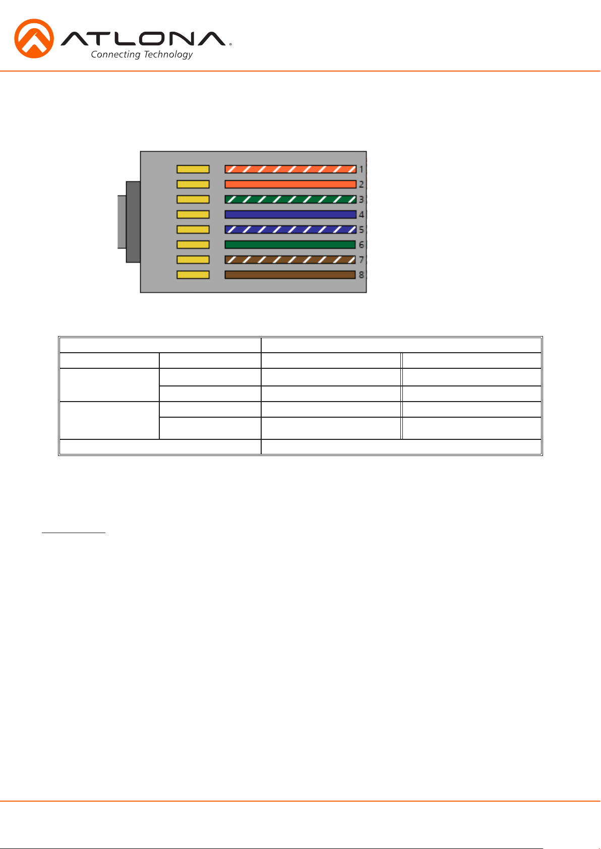
Category Cable
For the category cables used in the installation of these products, please be sure to use a 568B
termination as pictured below:
1. White - Orange
2. Orange
3. White - Green
4. Blue
5. White - Blue
6. Green
7. White - Brown
8. Brown
Use the table below to verify the best category cable for the installation.
Performance Rating Type of LAN cable
Wiring Shielding CAT5e/6 CAT6a/7
Solid
Stranded - Patch
cable
(Not recommended)
Termination Please use EIA/TIA-568-B termination
Shielded (STP/FTP)
Unshielded (UTP) ** N/A
Unshielded (UTP) * N/A
Shielded (STP/FTP)
*** ****
* N/A
Important! 4K (UHD) signals are sensitive to cable quality and installation technique. It is recommended to
use CAT6a/7 solid core cables for best results.
Note: For cable distances see the specifications on page 34
Connector
Connector type and size is very important to ensure extenders work correctly. Please use the
matching cable type with the correct RJ45 connector.
CAT5e cables should use only CAT5e RJ45 connectors
CAT6 cables should use only CAT6 connectors
CAT6a cables should use only CAT6a connectors
CAT7 cables should use only CAT7 connectors
Using the wrong size connectors may result in interference causing loss of signal.
Important! “EZ RJ45 connectors” are not recommended with HDBaseT extenders. Doing so may result in interference
with audio and video transmission.
atlona.com
6
Toll free: 1-877-536-3976
Local: 1-408-962-0515

Analog Multi-Function Inputs
The CLSO-612ED multi-function analog inputs (Input 5 and 6) can be used with most analog video
signal formats including VGA (with DDC), RGBHV (without DDC), component (YUV), S-Video, or
composite video. Balanced analog audio can be input and embedded using the provided captive
screw connectors.
Each format can be directly accessed from RS-232, IR, or IP control. Front panel buttons sequentially
progress through each input format. The last format used is the first source selected when returning
to these inputs. Unused formats can be removed from the sequence using the WebGUI, RS-232, or
IP.
VGA (m) to BNC, VGA (m) to RCA, and S-Video to 2 BNC adaptors can be used to connect sources
to these inputs.
VGA
Use a VGA to VGA cable to ensure that the Preferred Resolution DDC is communicated to your
source.
RGBHV
Use a HD-15 (VGA) to 5 BNC breakout cable for this format. An existing RGBHV analog matrix
switch can be connected here to maintain full function of the analog matrix.
Component
YUV (YPbPr) signal from DVD (or other sources) can be input to the CLSO-612ED using the green (Y),
blue (Pb), and red (Pr) connections on a HD-15 (VGA) to 5 BNC breakout cable or with a common
VGA (m)-Component (3 RCA m) adaptor.
S-Video
YC signal from a VCR or teleconference system can be input to the CLSO-612ED using the blue (Y),
and green (C) connections on a HD-15 (VGA) to 5 BNC (m) breakout cable and a common S-Video (m)
to 2 BNC (f) adaptor
Composite
NTSC, PAL, or Secam video signals can be input to the CLSO-612ED using the blue connection on a
HD-15 (VGA) to 5 BNC (m) breakout cable.
A common application for this type of input would be to connect a RGBHV matrix switcher to the
CLSO-612ED. Then each input to the matrix could be connected to a different format analog signal.
A 3rd party control system could ensure the correct format is selected to match the input to the
switcher.
atlona.com
7
Toll free: 1-877-536-3976
Local: 1-408-962-0515
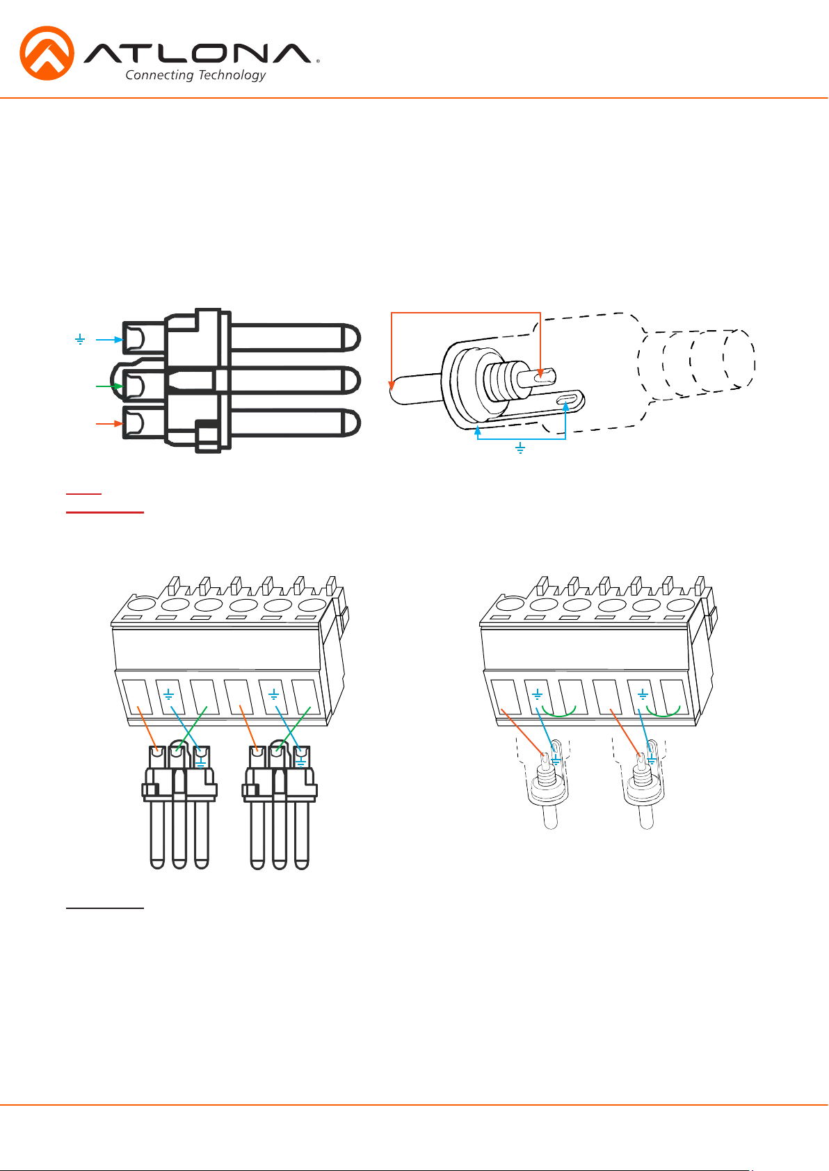
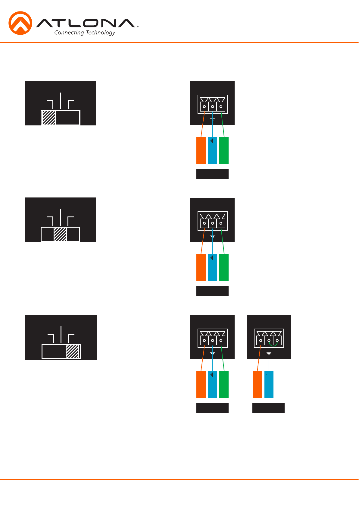
Analog Audio
A captive screw analog audio connector is provided to ensure a more reliable and secure
connection. The captive screw connector supports balanced and unbalanced audio output.
Balanced audio connections use two signal wires and a ground to minimize interference to an audio
signal over longer cable runs. Unbalanced audio connections use two wires for connection with
consumer audio components.
Audio can be routed to any input for use with VGA or other sources. View page 31 for commands.
XLR
1 ( )
3 ( - )
2 ( + )
Note: Pin outs may vary, please refer to the audio device’s manual to ensure a correct connection.
Important! When terminating cables, please ensure exposed adjacent wires do not touch. This may result in
a short that can damage connected devices.
BALANCED UNBALANCED
L / R
+
+
-
-
Tip (+)
Sleeve ( Ground)
L / R
+
+
-
RCA
-
Important! With unbalanced connections a jumper is needed between ground and negative to reduce noise
atlona.com
+
+
-
-
+ +
Toll free: 1-877-536-3976
8
Local: 1-408-962-0515
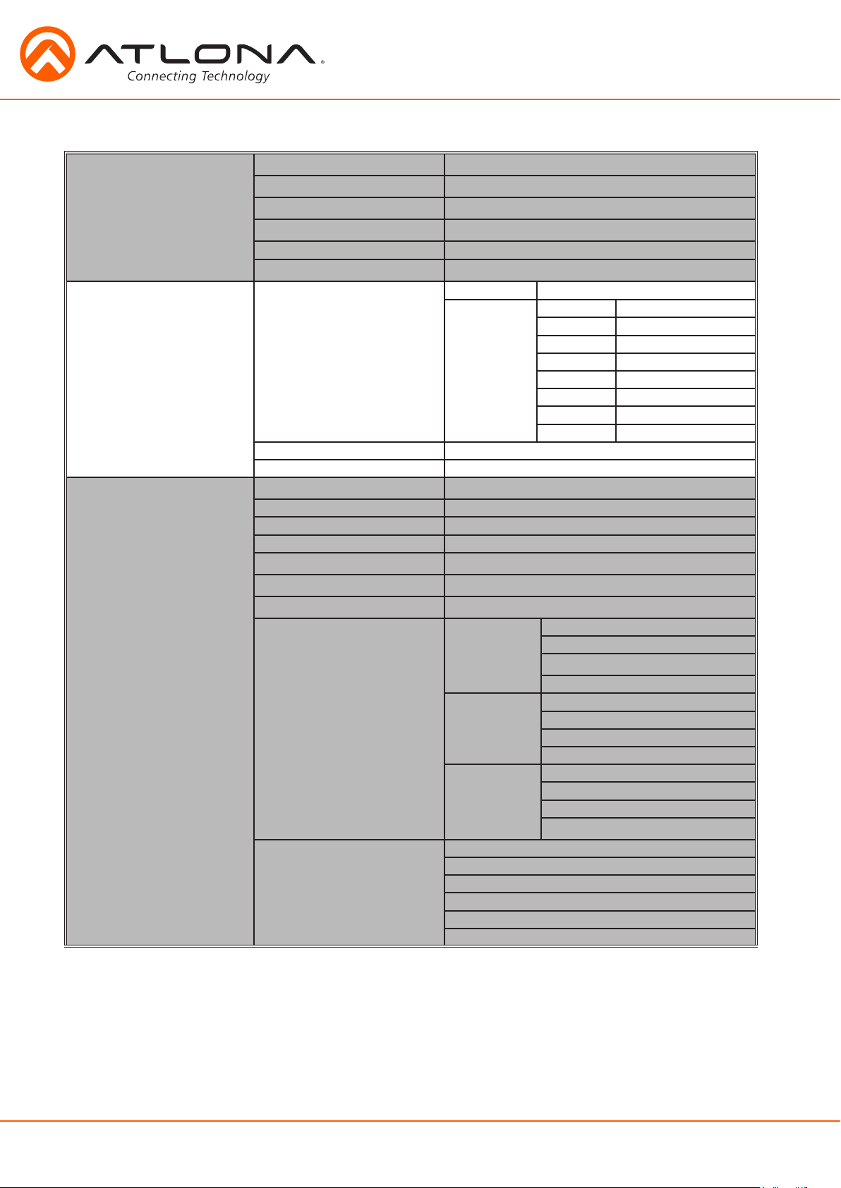
Microphone Connection
48V
48V
48V
MIC (Dynamic MIC)
MIC/LINE IN
MIC
LINE
Connect dynamic or self-powered microphones in
this mode.
MIC
LINE
Use this setting for phantom powered
microphones. Supplies 48 volts.
+
-
+
Positive
Ground Ground Ground
Negative
MIC
Balanced
MIC/LINE IN
+
-
+
Positive
Negative
MIC
LINE
Connect wireless microphone receivers (or other
sources) with line level outputs using this setting.
Either balanced or unbalanced connections may
be used.
MIC
Balanced
MIC/LINE IN
+
-
+
Positive
Negative
MIC/LINE IN
+
+
Positive
Ground
LINE LINE
Balanced Unbalanced
-
atlona.com
9
Toll free: 1-877-536-3976
Local: 1-408-962-0515
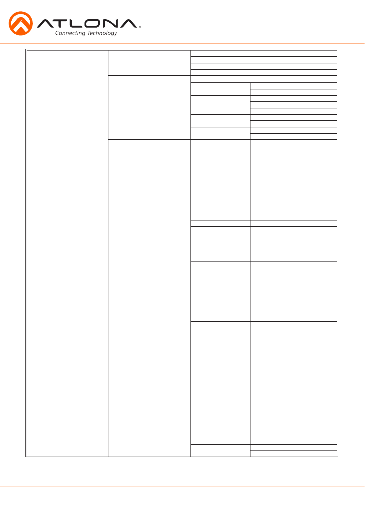
On Screen Display (OSD)
Input Input 1 HDMI 1
Input 2 HDMI 2
Input 3 HDBaseT 1
Input 4 HDBaseT 2
Input 5 VGA 1
Input 6 VGA 2
Audio Volume Master -80 to +10db
Sub HDMI 1 -80 to +10db
HDMI 2 -80 to +10db
HDBaseT 1 -80 to +10db
HDBaseT 2 -80 to +10db
Analog 1 -80 to +10db
Analog 2 -80 to +10db
Microphone -80 to +10db
Line In -80 to 0db
Bass -10 to 12 dB
Treble -10 to 12 dB
Video Contrast 0 to 100
Brightness 0 to 100
Sharpness 0 to 30
Color 0 to 100
Tint 0 to 100
H Position 0 to 40
Phase 0 to 63
NR BNR Disabled
Low
Medium
High
MNR Disabled
Low
Medium
High
RNR Disabled
Low
Medium
High
Scale Full
Overscan
Underscan
Letterbox
Panscan
Follow Input
atlona.com
10
Toll free: 1-877-536-3976
Local: 1-408-962-0515
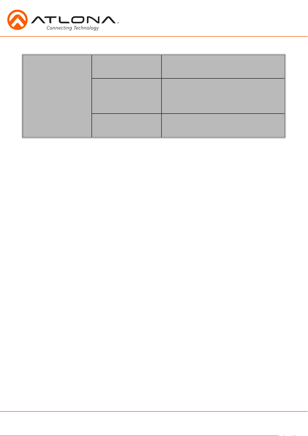
Setup Language English
Spanish
French
German
OSD Settings Transparency
Position Horizontal
Menu Timer 10 sec
Logo On
Info Banner On
Output Format HD Pass Through
Native
UHD 3840x2160p@24
PC-1 640x480@60
PC-2 1280x768@60
Network Network Status MAC Address
DHCP ON
Vertical
30 sec
60 sec
Off
Off
480i@60 (NTSC)
480p@60
720p@60
1080i@60
1080p@60
576i@50 (PAL)
576p@50
720p@50
1080i@50
1080p@50
1080p@24
3840x2160p@25
3840x2160p@30
4096x2160p@24
4096x2160p@30
640x480@72
640x480@75
800x600@60
800x600@72
800x600@75
1024x768@60
1024x768@72
1024x768@75
1280x800@60
1280x960@60
1280x1024@60
1360x768@60
1366x768@60
1400x1050@60
1440x900@60
1600x900@60
1600x1200@60
1920x1200@60
xx-xx-xx-xx-xx-xx
IP Address
xxx.xxx.x.xxx
Subnet
xxx.xxx.xxx.x
Gateway
xxx.xxx.x.x
OFF
atlona.com
11
Toll free: 1-877-536-3976
Local: 1-408-962-0515
Note: After selecting a new language, close the menu and reopen it for the change to take effect.
Status System Info Software Revision
OSD Revision
FPGA Revision
On-Time (h-m)
Video Info Input
Signal Type
Video Format
Aspect
Color Space
Color Depth
Audio Info Input
Audio Format
Sampling Rate
Channels
x.x.xx (e.g. 1.0.01)
x.x.x (e.g. 1.0.0)
x.x.x (e.g. 1.0.0)
x:xx (e.g. 1:15)
xxxx (e.g. HDMI 1)
xxxx (e.g. HDMI)
xxxx (e.g. 1080i@60)
xxxx (e.g. 16x9)
xxxx (e.g. YUV)
xxxx (e.g. 24)
xxxx (e.g. HDMI 1)
xxxx (e.g. PCM)
xxxx (e.g. 48 KHz)
xxxx (e.g. 2-Ch)
atlona.com
12
Toll free: 1-877-536-3976
Local: 1-408-962-0515
 Loading...