

Atlona AT-UHD-CAT-2 Installation Manual
1
Installation Guide
AT-UHD-CAT-2
4K/UHD
Two-Output HDMI to HDBaseT™ Distribution Amplier
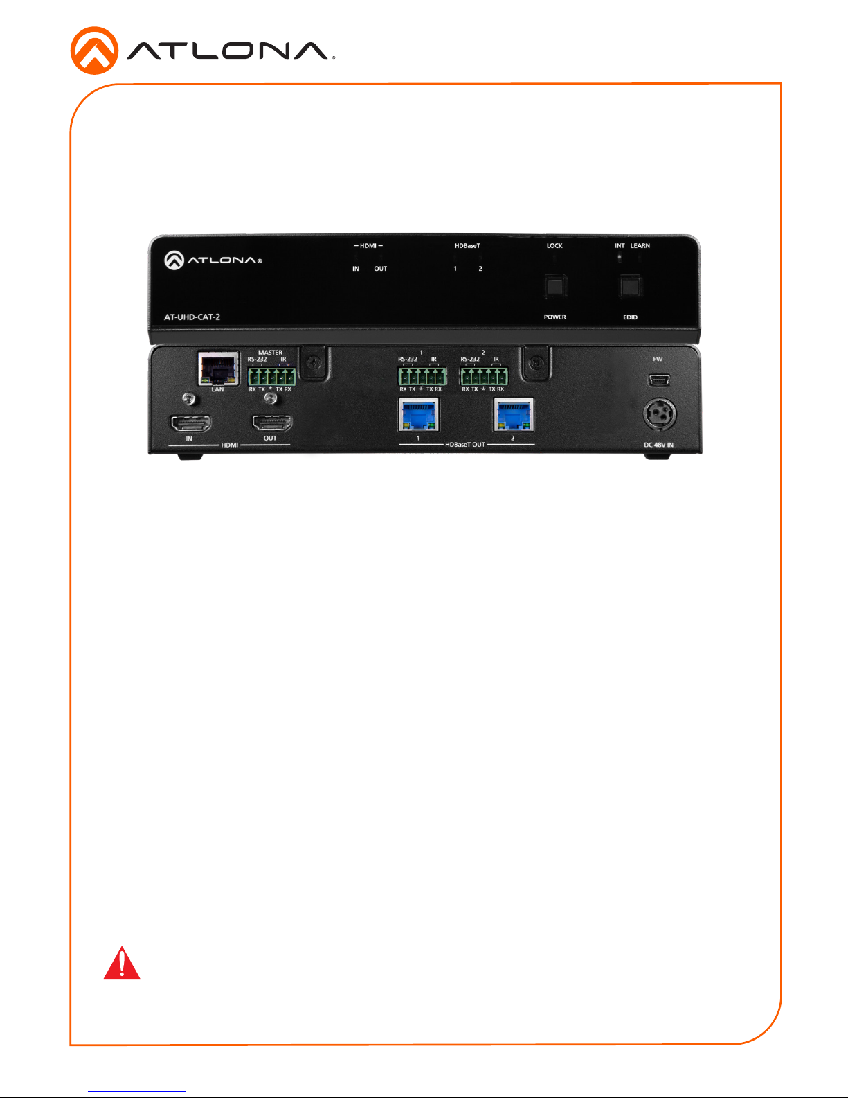
AT-UHD-CAT-2
The Atlona AT-UHD-CAT-2 is a 4K/UHD HDMI to HDBaseT distribution amplier featuring pass-
through HDMI input connections, two HDBaseT outputs, and display control capability. Each
output transmits AV and control signals up to 230 ft. (70 m) @ 1080p and 130 ft. (40 m) @ 4K/
UHD. Features include 4K/UHD @ 60 Hz with 4:2:0 color subsampling, HDCP 2.2 compliance,
EDID management, and PoE for powering remote receivers. A wide variety of consumer
displays may be controlled by the UHD-CAT-2 using CEC. Designed for commercial distribution
applications, the UHD-CAT-2 is control system-friendly and integrates with any TCP/IP, RS-232,
or IR control system and features a 1U, half-rack width enclosure with external, international
power supply. The UHD-CAT-2 is ideal for use with the AT-UHD-EX-70C-RX HDBaseT receiver,
AT-HDVS-200-RX HDBaseT receiver and HD scaler, or AT-HDVS-SC-RX HDBaseT receiver and
4K/UHD scaler.
IMPORTANT: Visit http://www.atlona.com/product/AT-UHD-CAT-2 for the latest rmware
updates and User Manual.
1 x AT-UHD-CAT-2
3 x Captive screw connector, 5-pin
1 x Rack ear (short)
1 x Rack ear (long)
2 x Mounting plates
4 x Mounting screws
1 x 48 V DC power supply
1 x Installation Guide
Package Contents
2
Installation Guide
AT-UHD-CAT-2
TX TXRX RX
21
21
RS-232
MASTER
IN
OUT
LAN
HDMI HDBaseT OUT DC 48V
IR FW
TX TXRX RX
RS-232 IR
TX TXRX RX
RS-232 IR
21OUTIN
HDMI HDBaseT LOCK
EDIDPOWER
AT-UHD-CAT-2
INT LEARN
21OUTIN
HDMI HDBaseT LOCK
EDIDPOWER
AT-UHD-CAT-2
INT LEARN
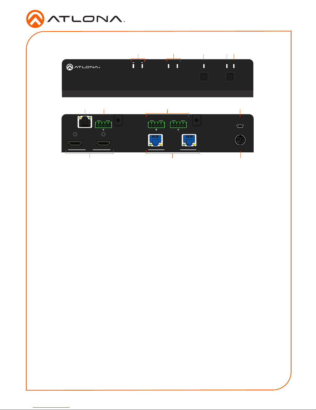
1 HDMI Indicators
Displays the status of the HDMI IN and
HDMI OUT ports. When connected
to a source or display (sink) device,
respectively, the LED indicator will be
blue.
2 HDBaseT Indicators
Displays the status of the HDBaseT OUT
ports. When connected to an HDBaseT
receiver, the LED indicator will be blue.
3 Lock
This LED will be blue when the unit is
locked.
4 INT
This LED indicator will be blue when the
unit is using an internal EDID.
5 LEARN
This LED indicator will ash when a
downstream EDID is being read into
memory. Refer to the User Manual for
more information.
6 LAN
Connect an Ethernet cable from this port
to the network.
7 HDMI
Connect an HDMI cable from the source
to the IN port. Connect an HDMI cable
from the display (sink) device to the OUT
port.
8 RS-232 / IR (MASTER)
Connect a control system or other DTE
device to this port to control the AT-UHDCAT-2.
9 RS-232/IR 1 / 2
Connect a control system or other DTE
device to these ports for pass-through
zone control. Each of these ports uses
the associated HDBaseT OUT port. This
allows RS-232 command data to be sent
to a display (sink) device connected to a
PoE-comptible receiver.
10 HDBaseT OUT
Connect Ethernet cables from these ports
to PoE-compatible receivers.
11 FW
Connect a mini USB-to-USB cable from
this port, to a computer, to update the
rmware of the AT-UHD-CAT-2.
12 DC 48V
Connect the included power supply to this
power receptacle.
Panel Descriptions
3 4
1 2
5
6 8 9 11
7
10 12
Front
Rear
3
Installation Guide
AT-UHD-CAT-2
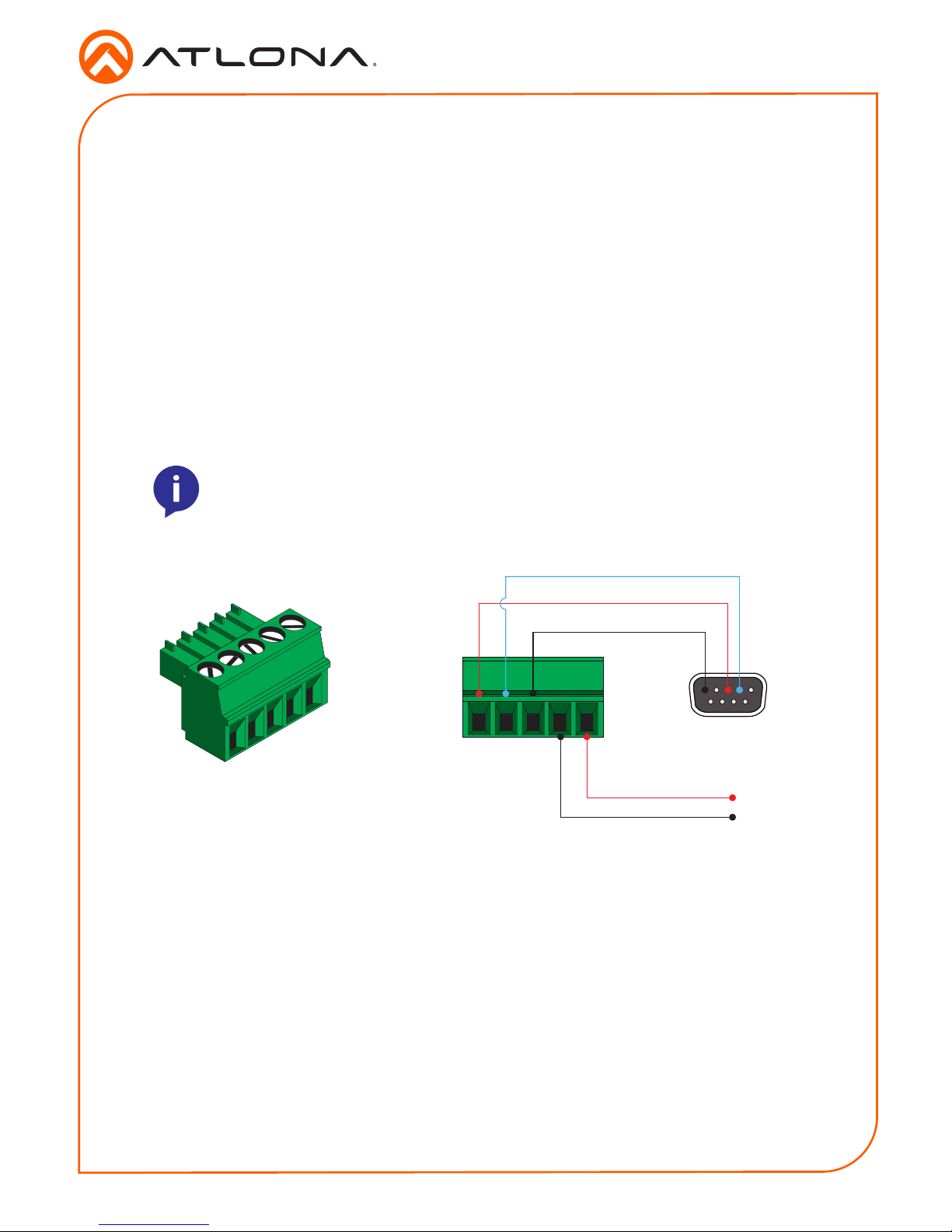
The AT-UHD-CAT-2 provides three RS-232 ports. The RS-232/IR MASTER port is used to
control the AT-UHD-CAT-2 using a control system or other DTE equipment. RS-232/IR 1 and
RS-232/IR 2 ports are used in conjunction with the HDBaseT OUT 1 and HDBaseT OUT 2
ports. RS-232 data is passed through over the the respective HDBaseT OUT port (zone) to a
sink device connected to a PoE-compatible the receiver. This step is optional.
1. Use wire strippers to remove a portion of the cable jacket.
2. Remove at least 3/16” (5 mm) from the insulation of the RX, TX, and GND wires.
3. Insert the TX, RX, and GND wires into correct terminal using one of the included 5-pin
captive screw connectors.
4. Tighten the captive screws to secure the wires in place. Do not over-tighten or use hightorque devices to prevent damage to the connector block.
NOTE: Typical DB9 connectors use pin 2 for TX, pin 3 for RX, and pin 5 for
ground. On some devices functions of pins 2 and 3 are reversed.
RS-232
GND
RX
TX
S
GND
4
Installation Guide
AT-UHD-CAT-2
1. Connect an HDMI cable from a UHD/HD source to the HDMI IN port.
2. Connect an HDMI cable from the HDMI OUT port to a display (sink) device.
3. Connect up to two Ethernet cables from the HDBaseT OUT ports to compatible PoEcapable receivers.
4. Connect an Ethernet cable from the LAN port to the Local Area Network (LAN). This step
will be required in order to access the built-in web server.
5. Connect the included power supply to the DC 48V connector and connect the power cord
to an available electrical outlet.
Installation
Optional
6. Connect an RS-232 or IR cable from the control system or other DTE device to the RS-232/
IR ports:
• MASTER RS-232/IR
Connecting to this port will provide direct control of the AT-UHD-CAT-2. Control can
be performed using either RS-232 or electrical IR.
• RS-232/IR 1 or RS-232/IR 2
Each of these ports is associated to the respective HDBaseT OUT port. This allows
RS-232 pass-through zone control of a display (sink) device that is connected to a
PoE-compatible receiver. Control can be performed using RS-232 or electrical IR.
By default, the AT-UHD-CAT-2 is set to DHCP mode, allowing a DHCP server (if present) to assign the unit an IP address. If a DHCP server is not found within 15 seconds, then the unit will be
placed in Auto IP mode and use a self-assigned IP address within the range of 169.254.xxx.xxx.
If DHCP or Auto IP mode are not desired, the unit can be placed into static IP mode by using the
POWER button on the front panel.
IP Conguration
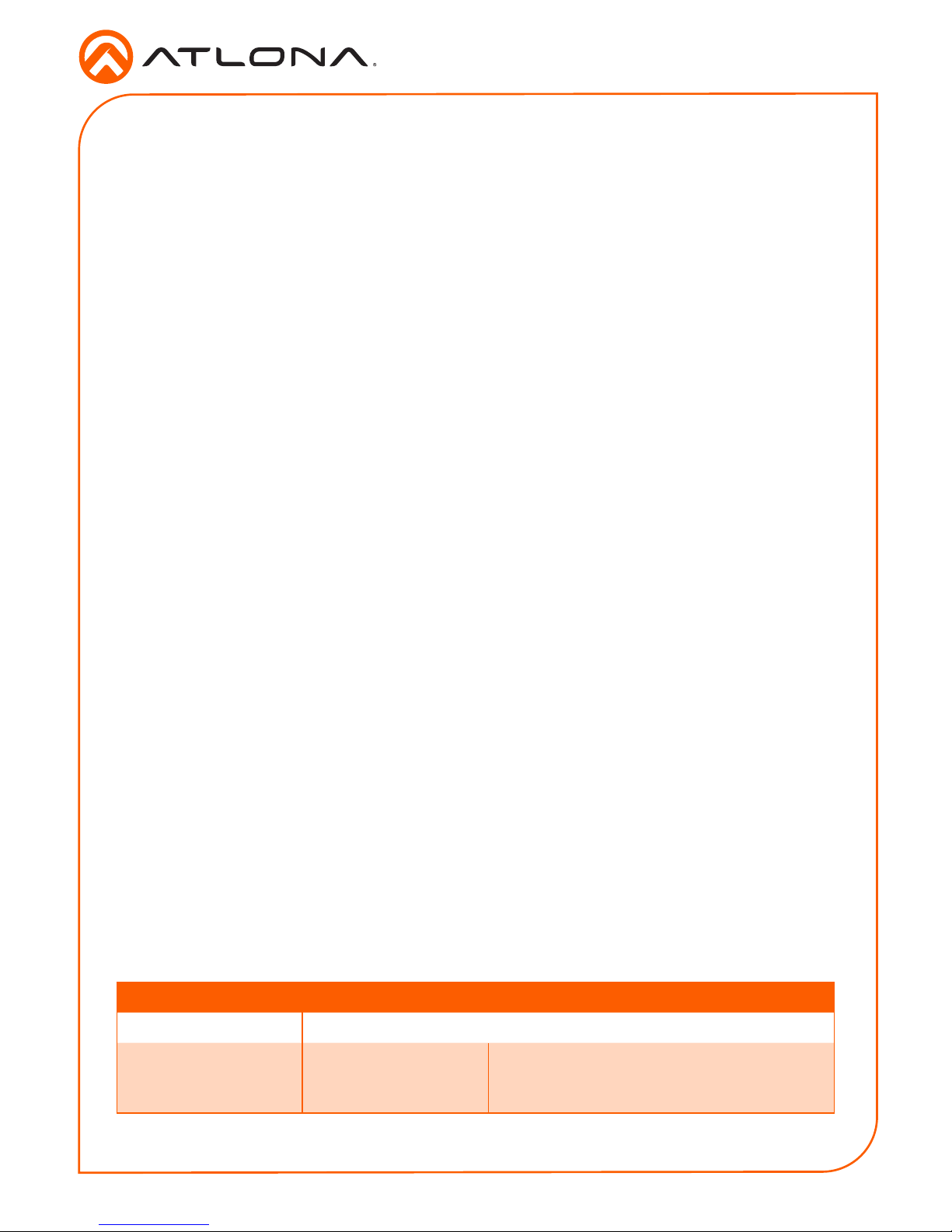
Press and hold the POWER button for approximately 15 seconds. Once the LOCK LED indicator
begins to ash, release the POWER button. The number of ashes will indicate the currently
selected IP mode:
LED ashes Description
Two DHCP mode
Four Static IP mode IP address: 192.168.1.254
Netmask: 255.255.255.0
Gateway: 192.168.1.1
Switching the IP mode
 Loading...