

Page 1
Installation Guide
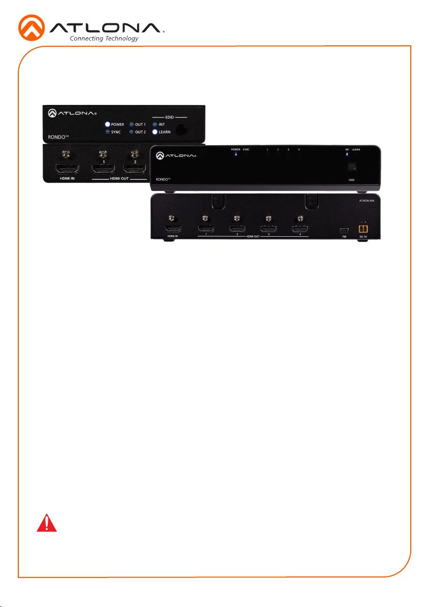
AT-RON-442 / AT-RON-444
4K HDR Two / Four-Output HDMI Distribution Amplier
AT-RON-442 / AT-RON-444
The Atlona Rondo™ series are HDMI distribution ampliers for high dynamic range (HDR)
formats. They are HDCP 2.2 compliant and support 4K/UHD video @ 60 Hz with 4:4:4 chroma
sampling, as well as HDMI data rates up to 18 Gbps. The Rondo series are ideal for applications
requiring the latest as well as emerging 4K/UHD and HDR sources and displays. They are
compatible with all video resolutions, audio formats, and color space formats supported in the
HDMI 2.0a specication, plus the ability to pass metadata for HDR content. The Rondo Series
HDMI distribution ampliers include EDID management features, front panel LED indicators
for power and signal status, and the capability to cascade several units without compromising
performance.
Package Contents
AT-RON-442
1 x AT-RON-442
1 x 5V DC power supply
1 x Phoenix terminal block, 2-pin
2 x Rack ears
4 x Rubber feet
4 x Screws
1 x Installation guide
IMPORTANT: Visit http://www.atlona.com/product/AT-RON-442 and http://www.atlona.
com/product/AT-RON-444 for the latest rmware updates.
AT-RON-444
1 x AT-RON-444
1 x 5V DC power supply
1 x Phoenix terminal block, 2-pin
2 x Mounting plates
1 x Long rack ear
1 x Short rack ear
4 x Rubber feet
4 x Screws
1 x Installation guide
1
Page 2
Panel Descriptions
RONDO
Installation Guide
AT-RON-442 / AT-RON-444
AT-RON-442
2 6 7431 5
EDID
POWER
TM
SYNC
OUT 1
OUT 2
INT
LEARN
AT-RON-442
HDMI IN
8 9
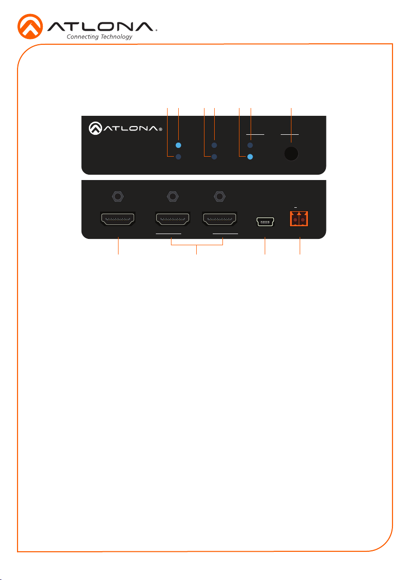
1 POWER
This LED indicator will glow solid blue
when the unit is powered.
2 SYNC
This LED indicator will glow solid blue
when an active source is detected on the
HDMI IN port.
3 OUT 1
This LED indicator will glow solid blue
when a display or other sink device is
connected to the HDMI OUT 1 port.
4 OUT 2
This LED indicator will glow solid blue
when a display or other sink device is
connected to the HDMI OUT 2 port.
5 LEARN
This LED indicator glows solid blue when
the unit is in LEARN mode.
6 INT
This LED indicator glows solid blue when
the unit is using the built-in EDID.
1 2
HDMI OUT FW DC 5V
10 11
7 EDID button
Press this button to switch between INT
and LEARN modes.
8 HDMI IN
Connect an HDMI cable from this port to a
UHD/HD source.
9 HDMI OUT 1/2
Connect an HDMI cable from each of
these ports to a display or other sink
device.
10 FW
Connect a mini USB cable to this port to
update the rmware.
11 DC 5V
Connect the included 5V DC power
supply to this port.
+
2
Page 3
AT-RON-444
2 5 63 41
Installation Guide
AT-RON-442 / AT-RON-444
TM
RONDO
HDMI IN
7
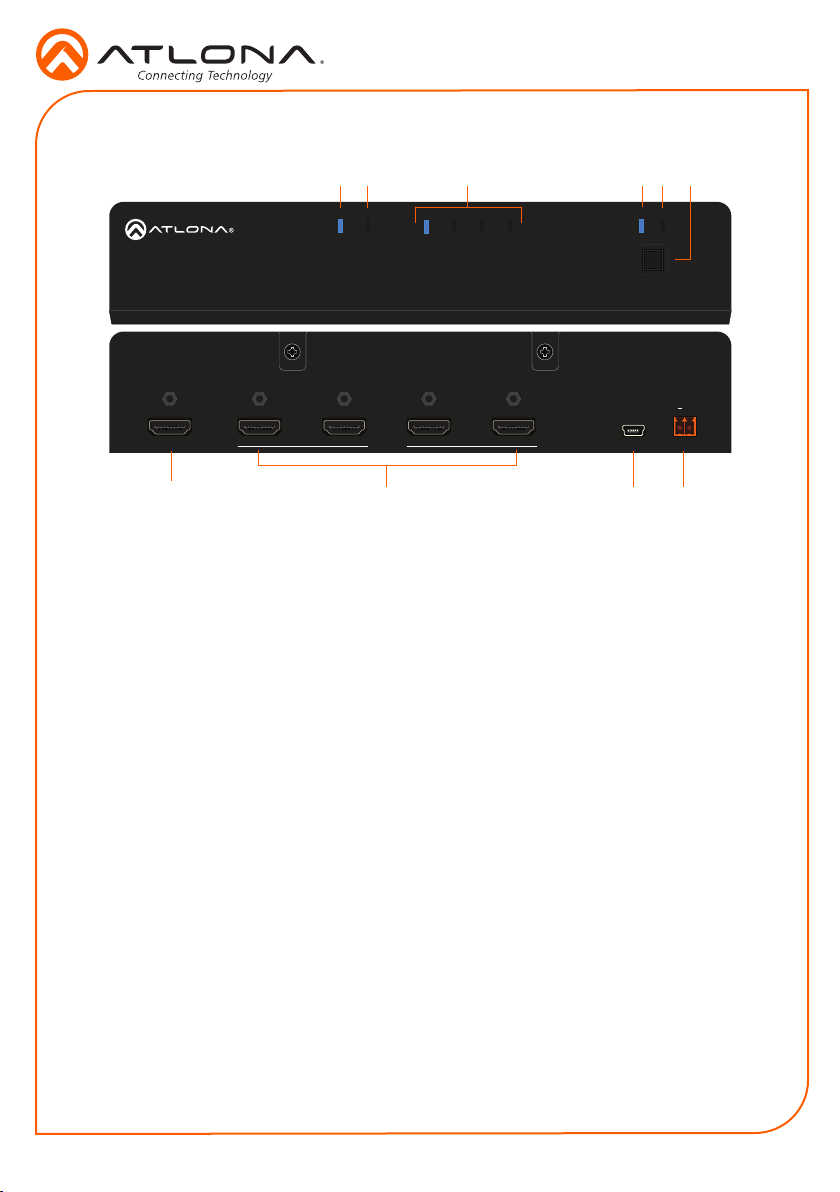
1 POWER
This LED indicator will glow solid blue
when the unit is powered.
2 SYNC
This LED indicator will glow solid blue
when an active source is detected on the
HDMI IN port.
3 Output Indicators
These LED indicator will glow solid blue
when a display or other sink device is
connected to the HDMI OUT ports.
4 INT
This LED indicator glows solid blue when
the unit is using the built-in EDID.
5 LEARN
This LED indicator glows solid blue when
the unit is in “EDID learn” mode.
POWER SYNC
HDMI OUT
8
6 EDID button
Press this button to switch between
“internal” and “learn” modes.
7 HDMI IN
Connect an HDMI cable from this port to a
UHD/HD source.
8 HDMI OUT 1/2/3/4
Connect an HDMI cable from each of
these ports to a display or other sink
device.
9 FW
Connect a mini USB cable to this port to
update the rmware.
10 DC 5V
Connect the included 5V DC power
supply to this port.
LEARN
INT1 2 3 4
EDID
AT-RON-444
+
4321
DC 5V
FW
9 10
3
Page 4
Installation Guide
1 2
HDMI OUT FW DC 5V
AT-RON-442
+
HDMI IN
1 2
HDMI OUT FW DC 5V
AT-RON-442
+
AT-RON-442 / AT-RON-444
Power Connector
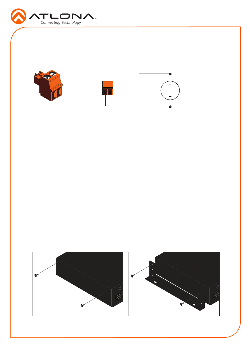
Locate the included orange Phoenix terminal block, and wire the included power supply to the
block as shown below. Do not use high-torque devices, when securing the wires, as this may
damage the screws and/or connector block.
White
5V DC
power supply
Black
Installation
1. Connect an HDMI cable from the UHD/HD source to the HDMI IN port on the AT-RON-442/
AT-RON-444.
2. Connect display/sink devices to the AT-RON-442/AT-RON-444 to the HDMI OUT ports.
The AT-RON-442 supports up to two outputs. The AT-RON-444 supports up to four
outputs.
3. Connect the included power supply to the DC 5V Phoenix connector.
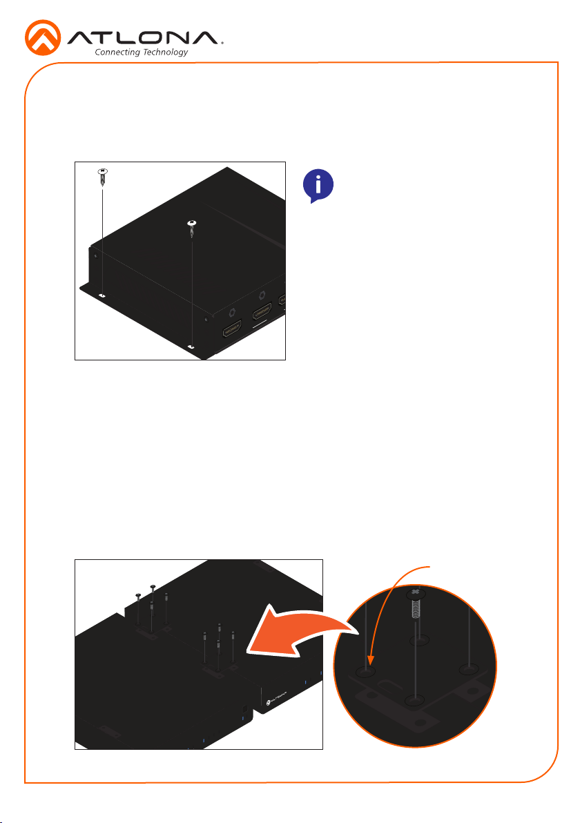
Mounting Instructions
The AT-RON-442 and AT-RON-444 each include two mounting brackets, which can be used to
attach the unit to any at surface.
AT-RON-442
1. Using a small Phillips screwdriver, remove the two screws from the left side of the
enclosure.
2. Position one of the mounting brackets, as shown below, aligning the holes on the side of the
enclosure with one set of holes on the mounting bracket.
3. Use the enclosure screws to secure the mounting bracket to the enclosure.
HDMI IN
4
Page 5
Installation Guide
INT
2 3 4
LEARN
EDID
2
FW DC 5V
AT-RON-442
+
AT-RON-442 / AT-RON-444
4. Repeat steps 1 through 3 to attach the second mounting bracket to the opposite side of the
unit.
5. Mount the unit using the oval-shaped holes, on each mounting bracket. If using a drywall
surface, a #6 drywall screw is recommended.
NOTE: Mounting brackets can
also be inverted to mount the
unit under a table or other at
surface.
1
HDMI OUT
HDMI IN
AT-RON-444
Two AT-RON-444 units can be connected to one another and installed in a 19” rack, using the
included mounting brackets. Alternatively, a single AT-RON-444 can be mounted in the rack
using the included spacer bracket.
Dual-unit rack installation
1. Turn the unit upside-down on a at surface.
2. Position the included mounting brackets over the pre-drilled holes on the bottom of the
enclosure. When attaching mounting brackets, the countersink bevels on the mounting
bracket should face upward.
Countersink bevel
TM
RONDO
EDID
LEARN
INT1 2 3 4
1
POWER SYNC
5
Page 6
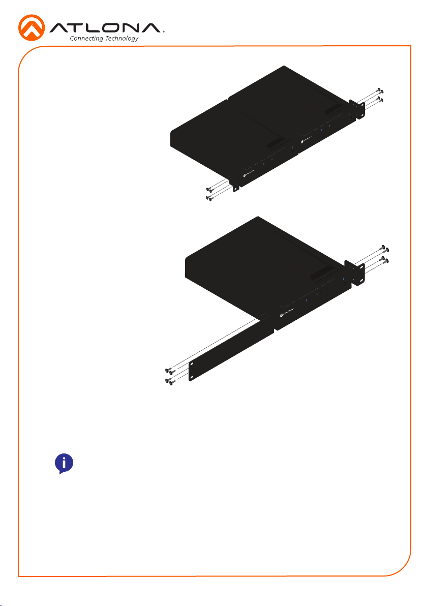
3. Turn the attached units over and
install the included rack ears to one
side of each enclosure using the
included screws.
Single-unit rack installation only
1. Attach the small rack ear to one
side of the AT-RON-444, using the
included screws.
2. Attach the longer rack ear to the
opposite side of the AT-RON-444
using the included screws.
Installation Guide
AT-RON-442 / AT-RON-444
LEARN
INT1 2 3 4
EDID
POWER SYNC
LEARN
INT1 2 3 4
AT-RON-444
TM
RONDO
+
EDID
POWER SYNC
AT-RON-444
TM
RONDO
LEARN
INT1 2 3 4
POWER SYNC
AT-RON-444
TM
RONDO
+
EDID
EDID
The AT-RON-442 and AT-RON-444 provide two EDID modes: internal (INT) and LEARN. Internal
mode selects the highest common resolution and audio between the source and all displays.
NOTE: 4K, 3D, and multichannel audio may not be available when using INT
(internal) EDID mode. When using this mode, the AT-RON-442 / AT-RON-444
will build an EDID, based on the capabilities of each display that is connected.
LEARN mode will copy the EDID information of the display/sink connected to the HDMI OUT 1
port.
To switch between internal and learn modes, press and hold the EDID button. While EDID is
being learned, the LEARN LED will blink. EDID learn is complete when the LEARN LED goes
solid.
6
Page 7
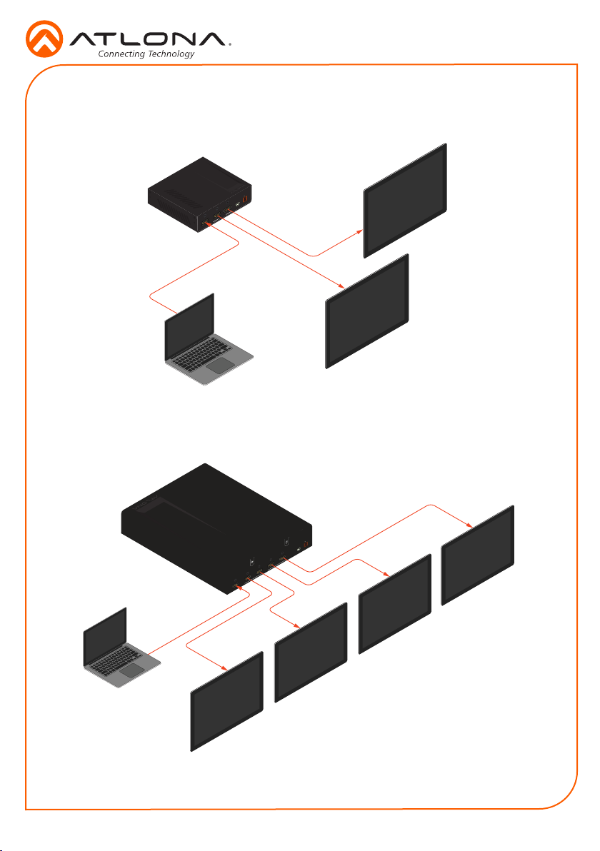
Connection Diagrams
Video
HDMI IN
1 2
HDMI OUT FW DC 5V
Laptop
AT-RON-442
AT-RON-442
+
AT-RON-442
Video
Video
AT-RON-444
Installation Guide
AT-RON-442 / AT-RON-444
HD/UHD display
HD/UHD display
Laptop
Video
HDMI IN
Video
HD/UHD display
AT-RON-444
HDMI OUT
AT-RON-444
+
DC 5V
FW
4321
Video
Video
HD/UHD display
Video
HD/UHD display
HD/UHD display
7
Page 8
Installation Guide
AT-RON-442 / AT-RON-444
Troubleshooting
Problem Solution
How do I perform a
rmware update on
the AT-RON-442 / ATRON-444?
Does the Rondo
series provide external
automation control?
3D content is not being
displayed.
If updated rmware is available, both rmware and update
instructions can be found under the Firmware tab of each of
the following links. Note that if new rmware is not available,
then the Firmware tab will not be displayed.
http://www.atlona.com/product/AT-RON-442
http://www.atlona.com/product/AT-RON-444
No.
• If using INT (internal) EDID mode, all connected displays
• To pass 3D content when not all displays support 3D,
Version 2
must be able to display 3D content. If only one of the
connected displays is not 3D-capable, then none of the
displays will show 3D content.
connect a 3D display to Output 1, then use the “learn
EDID” procedure.
atlona.com • 408.962.0515 • 877.536.3976
© 2017 Atlona Inc. All rights reserved. “Atlona” and the Atlona logo are registered trademarks of Atlona Inc. All other brand names and trademarks or registered
trademarks are the property of their respective owners. Pricing, specications and availability subject to change without notice. Actual products, product images, and
online product images may vary from images shown here.
8
 Loading...