

Atlona AT-PROHD88M-S, AT-PROHD88M-R User Manual
AtlonA
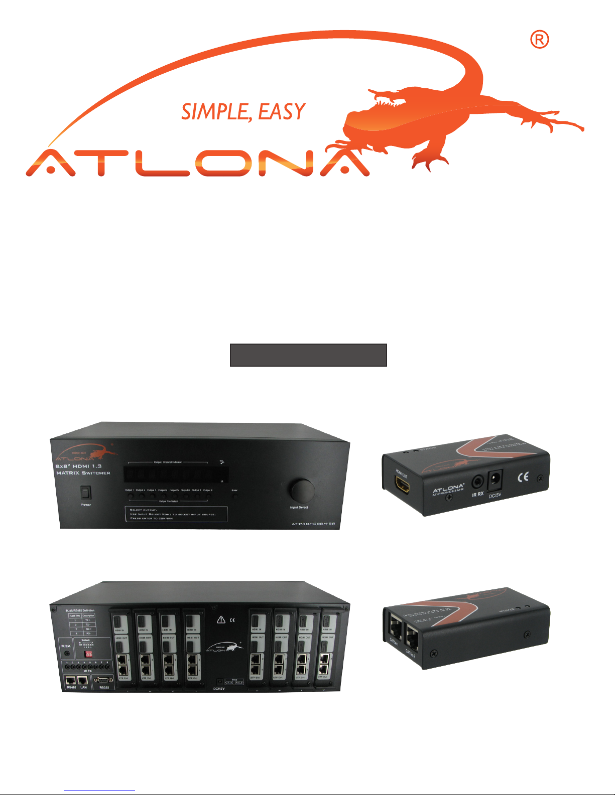
8X82 HDMI with IR Matrix Switcher
over CAT5
AT-PROHD88M-SR
User Manual
AT-PROHD88M-R
AT-PROHD88M-S
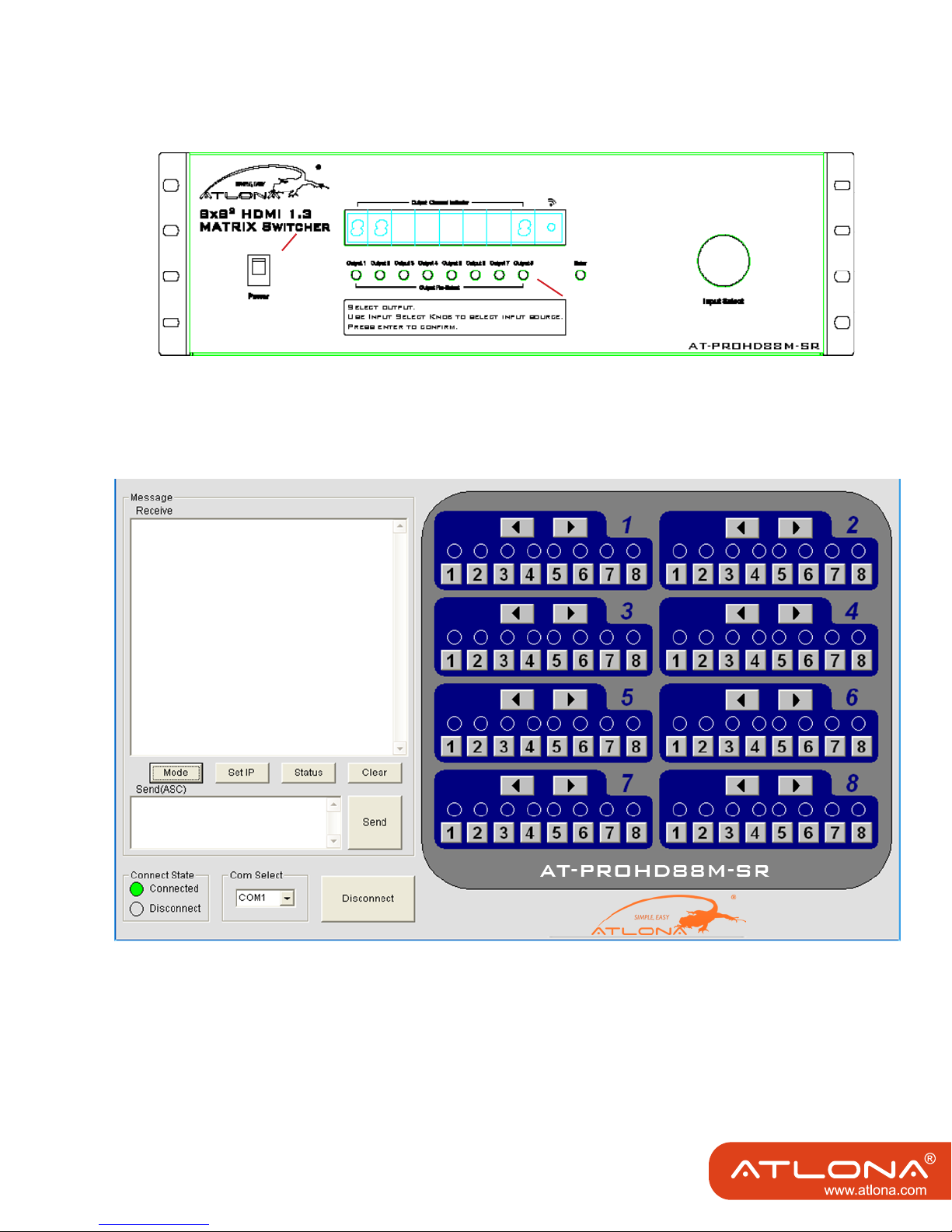
FRONT VIEW
FRONT VIEW
AT-PROHD88M-S
REAR VIEW
AT-PROHD88M-R
REAR VIEW

TABLE OF CONTENTS
1. Introduction .................................................. 1
2. Features .................................................. 1
3. Specication .................................................. 2
4. Package Contents .................................................. 2
5. Panel Descriptions .................................................. 3
5.1. Front Panel .................................................. 3
5.2. Rear Panel .................................................. 3
6. Connection and Operation .................................................. 5
6.1. Operation on front panel .................................................. 5
6.2. Control via RS232 .................................................. 6
6.2.1. The Interface of AT-PROHD88M-SR .................................................. 6
6.2.2. The Message Window .................................................. 7
6.2.3. The Com Status ................................................. 8
6.2.4. Control Command Format .................................................. 9
6.2.5. Control Code .................................................. 9
6.2.6. Read Status Command .................................................. 10
6.2.7. Web Password Reset .................................................. 10
6.2.8. AT-PROHD88M-SR RS-232 Remote
Control Protocol .................................................. 11
6.3. LAN Control .................................................. 14
7. IR Call-back from Remote Locations to Control
the AT-PROHD88M-SR .................................................. 16
8. Instruction of TX IR .................................................. 16
9. IR Cqdes .................................................. 17
10. Details on the EDID .................................................. 18
11. Maintenance .................................................. 20
12. Product Service .................................................. 20
13. Connection Diagram .................................................. 21
14. Safety Information .................................................. 22
15. Warranty .................................................. 23
16. Atlona Product Registration .................................................. 24

INTRODUCTION
Atlona’s AT-PROHD88M-SR is a true 8x8 HDMI matrix switcher. This unit allows any of the
eight HD source’s (i.e. Blue-Ray player, HD DVD player, satellite receiver, PS3, AppleTV etc.)
to be routed to any of the eight HD displays simultaneously. Users can choose several different ways of controlling the matrix: IR Back Channel, RS232, RS485, LAN and supplied remote
control. The Atlona AT-PROHD88M-SR comes with 8 x IR emitters for controlling sources next
to the switch as well as 1 x IR emitter for each one of the Twisted Pair Receiver units for controlling sources from other locations.
The AT-PROHD88M-SR has the ability of equalization, amplication and re-clocking the signal to ensure HDMI accurate signal transmission through long cables without quality loss. The
transmission distance of Twister Pair (Cat5/6) outputs can reach up to 100ft @ 1080P with
infrared control signal. Distance can be extended for additional 165ft with an optional Atlona
repeater unit AT-PROHD-RP. It is recommended to use CAT6 (568B terminated) wire to get the
longer distance.
The AT-PROHD88M-SR offers the perfect solutions for any digital entertainment center, digital
media show sites, retail show-rooms, Trade-Shows, High-End residential or commercial installs, education and medical environments or any other.
FEATURES:
• Allows up to eight HDMI devices to be independently switched to eight HDMI displays.
• High-resolutions support up to 1920x1200 or 1080p
• HDCP compliant.
• HDMI version 1.3.
• DVI Compatible
• Switcher outputs signal on both Twister Pair lines and direct HDMI output simultaneously,
therefore two displays could be active at the same time out of one output.
• The eight outputs are capable of displaying the same or different sources simultaneously.
Each output includes one HDMI A type connecter and a set of dual RJ-45 connecters as the
second mirrored HDMI output. The two outputs work simultaneously.
• EDID Memory function, which already includes most common displays EDID information
• Discrete IR back channel.
• Six switching modes: panel buttons, local IR, IR call back from remote locations, RS232,
RS485 and Ethernet.
• Eight IR emitters to control the HDMI sources.
SPECIFICATIONS
Operating Temperature Range -5 to +35°C (-41 to +95 °F)
Operating Humidity Range 5 to 90 % RH (no condensation)
Input Video Signal 0.5-1.0 volts p-p
Input DDC Signal 5 volts p-p (TTL)
Format Supported DTV/HDTV:1080P/1080i/720P/576P/480P/576i/480i
Audio Format Supported DTS-HD, Dolby tureHD, 7.1ch and others
HDMI Standard HDMI 1.3 (compatible with previous versions)
Maximum Transmission Distance <50ft on the direct HDMI output
UTP cable Transmission Distance <130ft with Twister Pair Receivers, if longer distance is
IR wave-length & frequency Wave-length: 940nm IR frequency: 38KHZ
Power Consumption 35wtts (Max)
Dimensions (Inch) 17.3L×7.9W×1.7H
Weight (Main Unit) 7.6 LB
PC: VGA, SVGA, XGA, SXGA, UXGA, WXGA,
WSXGA, WUXGA
required, we offer optional UTP Repeaters
Note: Specications are subject to change without notice.
PACKAGE CONTENTS
Master Unit
1. 1 x AT-PROHD88M-SR
2. 8 x IR emitter cables (marked IR TX),
3. 1x IR receiver cables (marked IR RX)
4. 1 x USB to RS232 cable
5. 1 x 12VDC Universal Power Supply. (UL Listed)
6. 1 x Rack Mounting ears.
7. 1 x IR Remote.
Slave Unit
1. 8 x Receiver Units AT-PROHD88M-R
2. 8 x IR receiver cables (marked IR RX),
3. 8X 5VDC power supply,
4. 8x Rack Mounting ears.
1. 1 x Operating Instructions.
2. 1 x CD with RS232 commands and control software.
2
PANEL DESCRIPTIONS
AT-PROHD88M-S
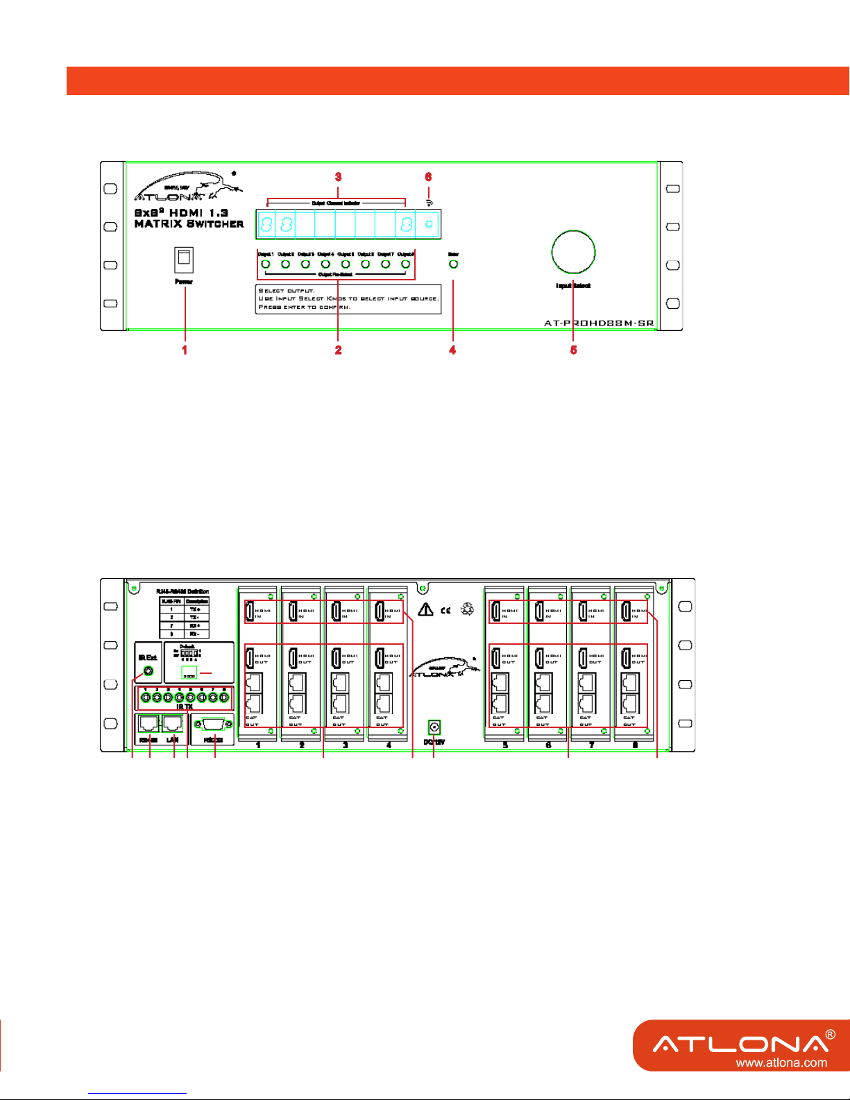
Front Panel
1. Power switch.
2. Output selection push-buttons (Use it to choose the preferred output channel).
3. LED indicator of input for output port 1 to 8.
4. Action Conrmation Button (Push the ‘Enter’ button to conrm the changing of input channel to the output).
5. Input selection knob. (Turn to select the proper input to the output)
6. IR window.
Rear Panel
1 2 3 4 5 6 7 8 109
1. IR extension. 7. Input ports 1 to 4.
2. RS485 port. 8. Power input.
3. LAN port. 9. Output 5 and 8 with HDMI and CAT5E.
4. IR emitter, corresponding to the Input port from 1 to 8 10. Input ports 5 to 8.
5. RS232 port. 11. DIP switch setting.
6. Output 1 to 4 with HDMI and CAT5E.
Note: The RS232 port and LAN port are for matrix control. The LAN port is connected to the computer via cross UTP
(568A+568B) and connected to the router or switcher via direct UTP.
3
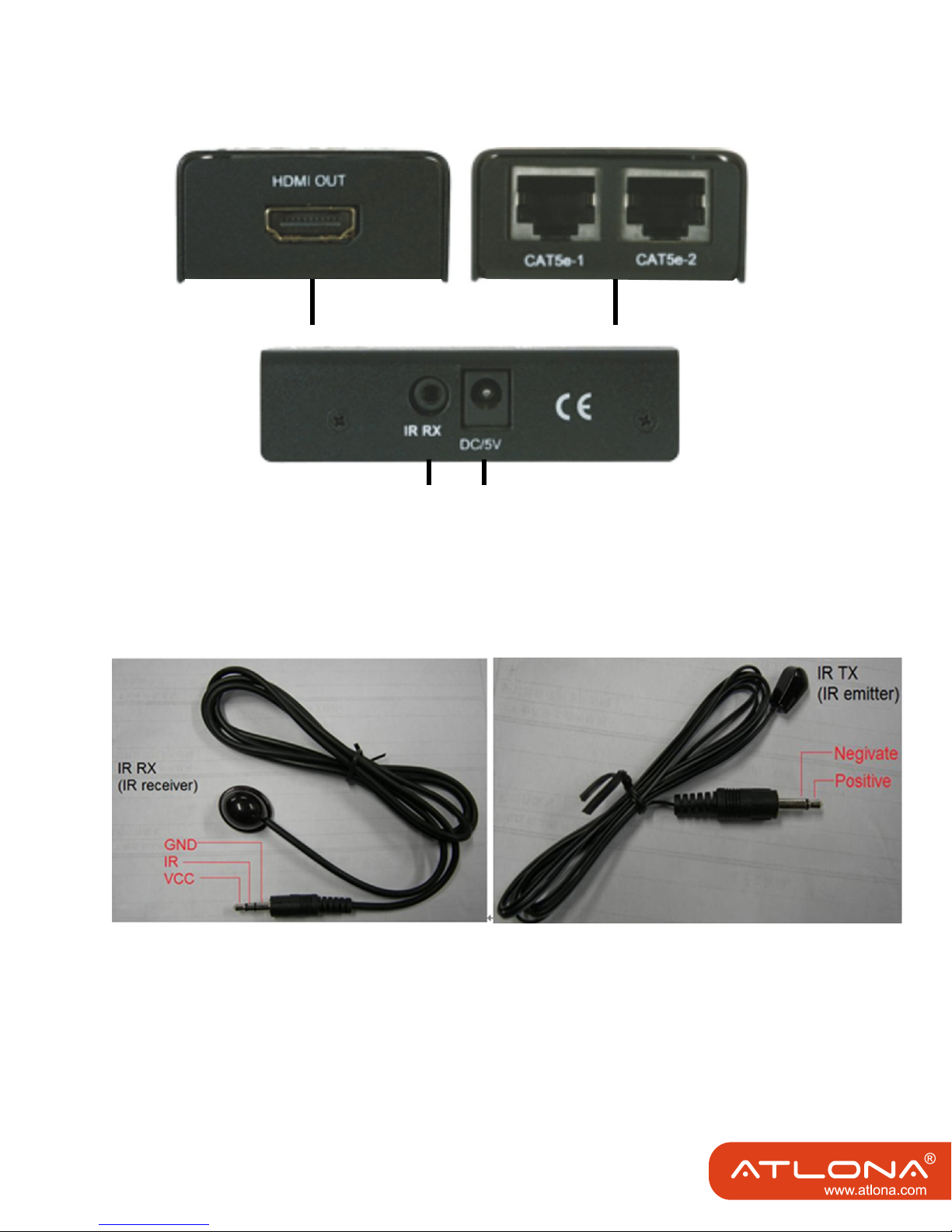
AT-PROHD-RP
1. HDMI output.
1
3
4
2
2. CAT-5e/6 input1 and input2.
3. Power input, 5VDC. (power supply is not required if used within suggested distance)
4. IR Receiver INPUT
Note: IR emitter should be placed as near to the IR eye as possible.
4

CONNECTION and OPERATION
1. Connect the HDMI input sources (such as HD-DVD, PS3, STB, AppleTV etc) into the AT-PROHD88M-SR.
2. Connect the standard HDMI outputs (such as LCD or DLP) into AT-PROHD88M-SR.
3. Connect two CAT-5E or CAT-6 cables to both Twisted Pair outputs of the unit and receiver Twister Pair inputs.
Please pay attention to the sequence of the two cables, CAT5/6-1->CAT5/6-1, CAT5/6-2->CAT5/6-2. (The cable
termination must follow the standard of EIA/TIA 568B for the longest distance;
4. Connect the HDMI output (such as: LCD or DLP) into the Twister Pair inputs on the receiver.
5. Connect the IR receiving cable into HDMI receiver IR RX and connect the IR TX cable into the main switcher IR
emitter.
6. Power on the input source you want to view. (Keep the unused input powered off, otherwise it may interfere.)
7. Connect the power supply into AT-PROHD88M-SR
8. Turn on the power. When the LED panel stops ashing, the initialization of the unit is ready.
9. Turn on the displays you want to watch.
10. Use the remote supplied or manually push the button on the front panel to choose input source.
Also use infrared extension receiver, RS232, RS485 or LAN port to do the control.
6.1. Operation on front panel.
1. Press the output select button for the output channel which you want to change. Corresponding LED of the
output channel will blink slowly.
the LED Flash
press the output
select push button
2. Rotate the input Knob to choose the desired input channel.
Rotate the input select knob to choose the desired
input channel
5
3. Press the ‘Enter’ button to conrm the action. LED will stops blinking.
the LED stops ashing
press the enter push
button to conrm the action
6.2. Control via RS232
6.2.1. The Interface of AT-PROHD88M-SR
6
 Loading...