

Atlona AT-PROHD48M-R, AT-PROHD48M-S Service Manual
www.atlona.com | toll free: 1-877-536-3976
For International: 1-408-962-0515
AT-PROHD48M-R
AT-PROHD48M-S
Service Manual
AtlonA
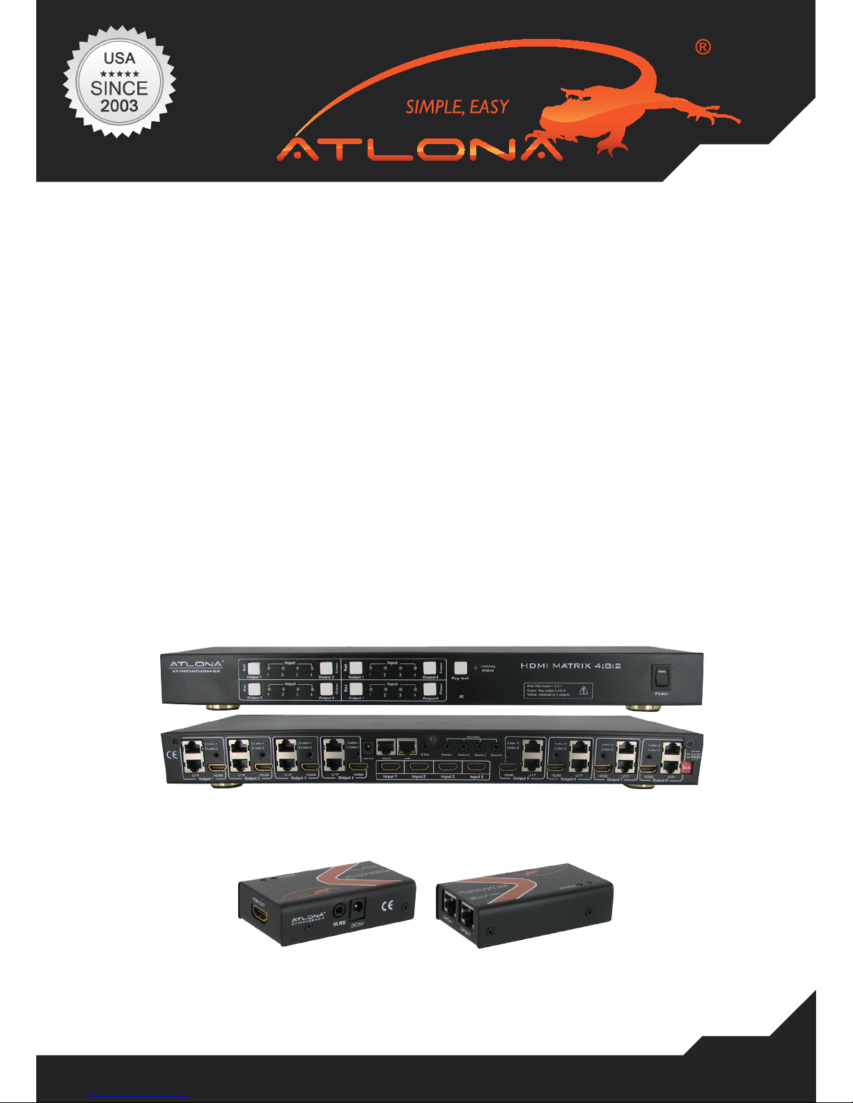
4x8 HDMI matrix Switch with
8 x CAT5 Receivers included
AT-PROHD48M-SR

www.atlona.com | toll free: 1-877-536-3976
For International: 1-408-962-0515
2
TABLE OF CONTENTS
1. Setting Up CAT5e/6/7 .................................................. 3
2. No Power on the Extenders .................................................. 3
3. Image is Bad/Flickers .................................................. 3
4. HDMI Receiver Baluns .................................................. 4
5. IR Issues/Call Back/Operation .................................................. 4
6. EDID Settings .................................................. 5
7. IR Remote Control .................................................. 7
8. No Audio. .................................................. 7
9. HDCP Keys .................................................. 7
10. UPC/ APC Back Ups .................................................. 7
11. Controlling VIA RS232 .................................................. 8
12. LAN Control .................................................. 9
13. No Signal on HDMI and CAT5 Out .................................................. 12
14. Using Other Sources Without HDMI .................................................. 12
www.atlona.com | toll free: 1-877-536-3976
For International: 1-408-962-0515
3
SETTING UP CAT5E/6/7
NO POWER ON THE EXTENDERS
IMAGE IS BAD/FLICKERS
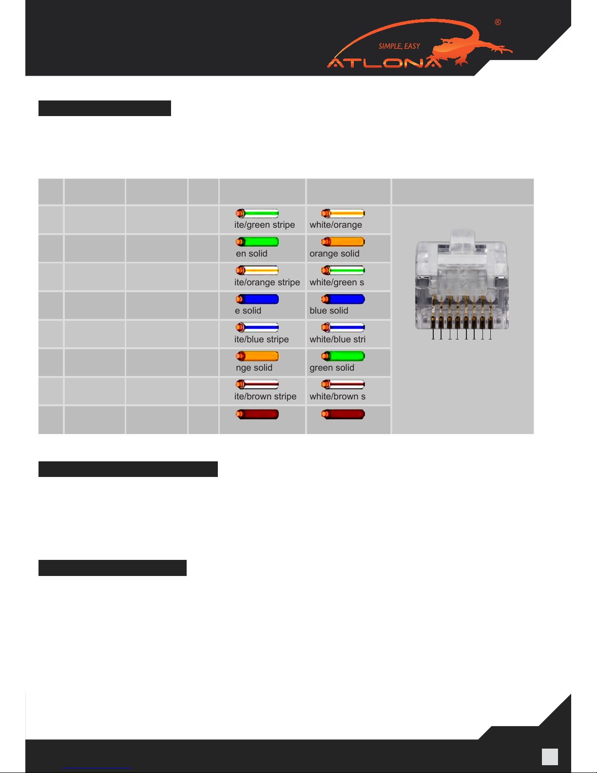
CAT5E or higher is recommended for use with the Atlona AT-PROHD48M-SR. If cables are run in the
walls make sure to stay away from light xtures, electrical boxes, uorescent lights, and any or other
electrical cables to reduce and prevent signal degradation. T568B termination needs to be used for this
device.
Pin T568A Pair T568B Pair Wire T568A Color T568B Color Pins on plug face
(socket is reversed)
1 3 2 tip
white/green stripe white/orange stripe
2 3 2 ring
green solid orange solid
3 2 3 tip
white/orange stripe white/green stripe
4 1 1 ring
blue solid blue solid
5 1 1 tip
white/blue stripe white/blue stripe
6 2 3 ring
orange solid green solid
7 4 4 tip
white/brown stripe white/brown stripe
8 4 4 ring
brown solid brown solid
If the unit is not powering-on please double check the surge protector/ outlet that the unit is connected
to. A Volt Meter can also be used to check the unit and the power supply needs to be outputting 12V
DC (110/240v universal).
1 2 3 4 5 6 7 8
Pin Position
The image ickers, goes in and out, or there is snow like affect, there are multiple reasons for this issues. Check all the connections HDMI and CAT5E/CAT6 and make sure they are fully connected and
are not loose. Check to see the CAT5E/CAT6/CAT7 terminations are fully crimped. CAT5E/CAT6/CAT7
is pick¬ing interference from other cables in the wall. Shielded cables are recommended to be run in
the walls. CAT5E/CAT6/CAT7 wall plates or CAT5 terminal blocks should not be used as they can also
cause inter¬ference in the signal; it needs to be connected with cables direct. The CAT5E/CAT6/CAT7
cables should not exceed the distance they are meant to be run at. It is important to use T568B termination on the CAT5E/CAT6/CAT7 cables.
www.atlona.com | toll free: 1-877-536-3976
For International: 1-408-962-0515
4
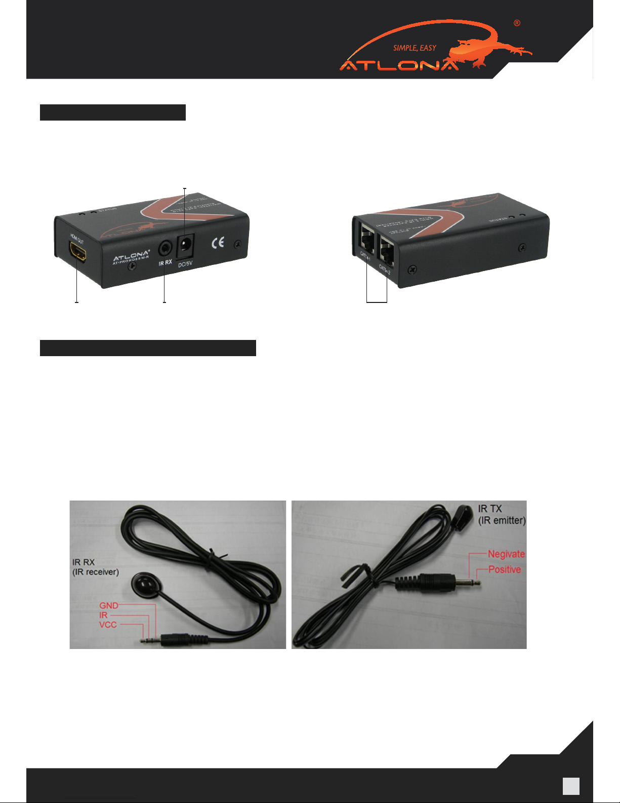
RJ45 Inputs
IR Input RX
Power Input
HDMI Out
HDMI RECIEVER BALUNS
The RJ45 inputs – please be careful when connecting RJ45 # 1 and # 2 inputs. They absolutely have
to match the outputs on the switch. Output # 1 should be connected to Input # 1 and Output # 2 should
be connected to Inputs # 2.
IR ISSUES /CALL BACK/OPERATION
VERY IMPORTANT:
When connecting IR receivers and IR emitters, be very careful as if they are reversed the IR Eye will
burn-out and also may damage the IR module inside of the switch and Receiver.
When installing IR’s, the IR TX (Transmitter) is used on Sources. The eye should be placed over the
Source IR eye on most applications. If their signal issues for example, device is not switching, there is
lag, the IR is being over ooded. Place the IR TX to the side of the IR eye or up or down to x the issue.
NOTE: the IR on the switch is 36 kilohertz if your source (DVD, blue-ray, cable box is higher the signal
will not pass)
The IR RX (Receiver) should be placed in a visible location for the remote to pick up the signal.
TX – Connects to the Switch
RX – Connects to the HDMI Receivers
IR calls back from remote locations allows controlling the matrix switch as well as nearby sources (such
as DVD, AppleTV, Satellite, Cable and etc…).
To enable the function: press the output2 selection button and the key lock button at the same time for
about 3 seconds. After all the output1 LEDs and the output2 LEDs ash once, the function is enabled.
www.atlona.com | toll free: 1-877-536-3976
For International: 1-408-962-0515
5
To disable the function: press the output2 selection button and the key lock button at the same time for
about 3 seconds. After all the output1 LEDS and the output2 LEDS ash twice, the function is disabled.
The sequence of “IR1, IR2, IR3, IR4” one-to-one correspond with “HDMI INPUTS1 through 4”. When an
output chooses certain input, the call-back IR signal of RJ45 on this output will choose the corresponding “IR” port to send the signal out.
For example, OUTPUT1 chooses INPUT3, and then the call-back IR signal of RJ45 on OUTPUT1 will
choose “IR 3” to send the signal out.
Note: The switcher can only accept and route IR signal which doesn’t exceed 38 KHz. In other words, if you are
trying to send IR signal from the remote location though out HDMI receiver and the IR signal is higher than 38
KHz, the IR signal will not pass though.
EDID SETTINGS
(PLEASE READ, IT IS VERY IMPORTANT)
When any of our HDMI/DVI distribution ampliers are powered on, they will automatically go through
an Identication cycle, which means that each output will send an EDID call back request to each one
of the display. Once that done, the distribution amplier will identify the data received and choose the
most appropriate EDID setting. The EDID setting chosen will be compatible with all the displays.
The reason why we manage EDID the way we do is because we want to make sure that user will always get signal.
If customer does want to send higher resolution to all the displays which are 1080p and lower resolu-
tion to the 720p display, we do offer a up/down scaler box which would be able to scale 1080p down to
whatever the TV’s native resolution is.
When it comes to our larger matrix switchers, starting at 4x8, we allow users to choose the EDID. User
can even choose 1080p and 7.1 Channel Audio, even though some displays may not be compatible. In
this case no audio or video will appear on the displays that can’t
Support it; however since it is a matrix switch some inputs not always have to be selected and therefore
the EDID settings are the way they are.
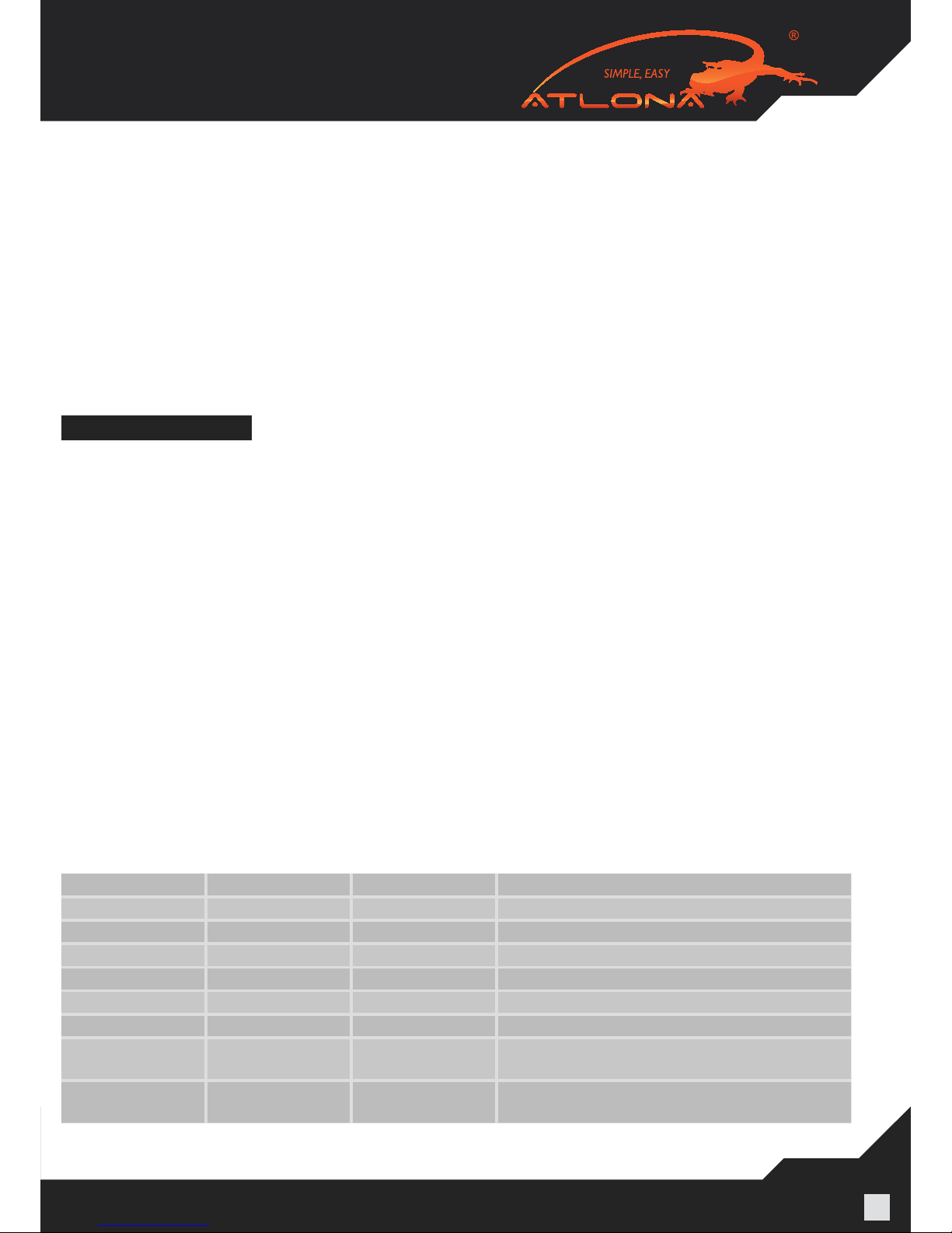
The functionality of the switch will depend on how you select the DIP Switches below. Please read the
instruc¬tions and explanations below to understand the purpose of different congurations. There are
four DIP switches on the back of the 4x4 matrix switcher. Below you will nd the denition of each one
of the dip switches.
Position1 Position2 Position3 Function
0 0 0 AUTO EDID MANAGEMENT (note # 1)
0 0 1 Copy EDID from output #1 (note # 2)
0 1 0 1080P with Stereo Audio (note#3)
0 1 1 1080i/720p with Stereo Audio (note#4)
1 0 0 1080P with 5.1 Audio (note#5)
1 0 1 1080P with 7.1 Audio (note#6)
1 1 0 AUTO EDID MANAGEMENT
with one RJ45 (OPTIONAL) (note#7)
1 1 1 Copy EDID from output #1
with one RJ45 (OPTIONAL) (note#8)
EACH TIME DIP SWITCHES ARE CHANGED; THE ATLONA SWITCH HAS TO POWER CYCLED.
 Loading...