

Page 1
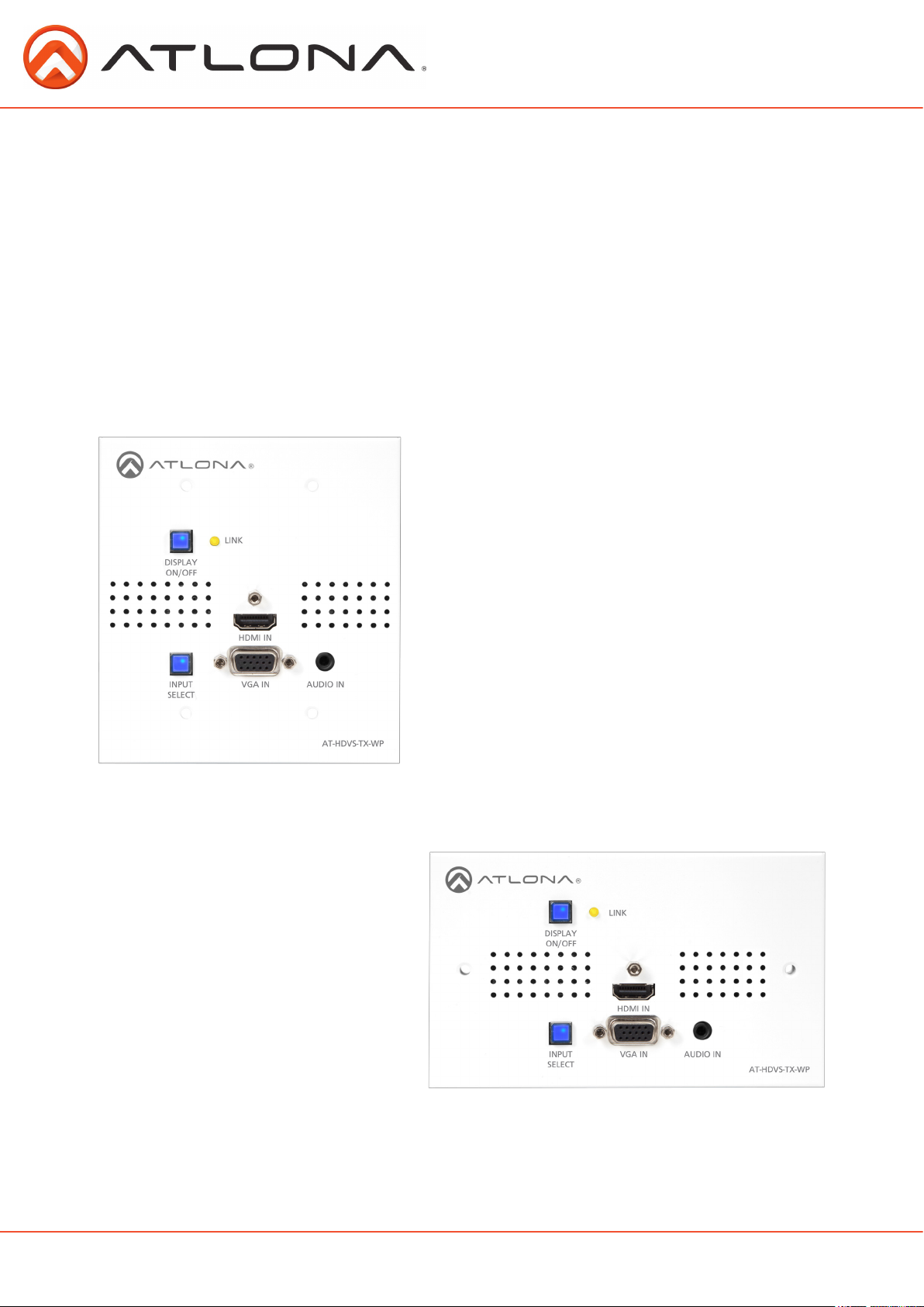
Atlona HDMI and VGA/audio
to HDBaseT Transmitter
Wall Plate
AT-HDVS-TX-WP
US
User Manual
UK
atlona.com
Toll free: 1-877-536-3976
Local: 1-408-962-0515
Page 2

Table of Contents
1. Introduction ........................................................................................ 3
2. Package Contents ........................................................................................ 3
3. Features ........................................................................................ 3
4. Panel Descriptions ........................................................................................ 4
5. Face Plate change ........................................................................................ 4
6. Installation ........................................................................................ 5
7. Connection ........................................................................................ 6
8. Specifications ........................................................................................ 7
9. Safety Information ........................................................................................ 8
10. Warranty ........................................................................................ 9
11. Atlona Product Registration ........................................................................................ 10
atlona.com
2
Toll free: 1-877-536-3976
Local: 1-408-962-0515
Page 3

Introduction
Atlona HDVS transmitter wall plate was designed to smooth the transition from analog to digital
displays in schools and businesses, allowing advanced HDMI display devices to be used with both
HDMI sources and the many VGA computers still in use. HDBaseT and power over category cable
(PoCc™) allow signal and power over a single category cable, with RS-232 control capability.
Used in a simple system with the Atlona HDVS-RX, this wall plate can be located up to 230 feet (70
meters) away from the display, turn the projector on / off and is connected with a single cable. No
power supply is required at the wall plate.
Package Contents
• 1 x AT-HDVS-TX-WP
• 2 x Wall plate covers (US & UK)
• 4 x Screws (US #6)
• 2 x Screws (UK 3.5mm)
• 1 x User manual
Features
• HDMI and VGA/analog audio inputs
• Auto-switching for easy input managing
• Extends resolutions of 1080p or 1920x1200 up to 230 feet (70 meters)*
• Custom wall plate configurations available (Call Atlona for details)
• Embeds analog audio onto HDBaseT output when using VGA input
• Firmware upgrade via USB for easy field service
Features when used with HDVS-RX
• PoCc (Power over Category cable), receive power from the receiver
• RS-232 display control
• 2-channel, balanced, analog audio to drive amplifiers (Ex. AT-PA100-G2)
atlona.com
3
Toll free: 1-877-536-3976
Local: 1-408-962-0515
Page 4
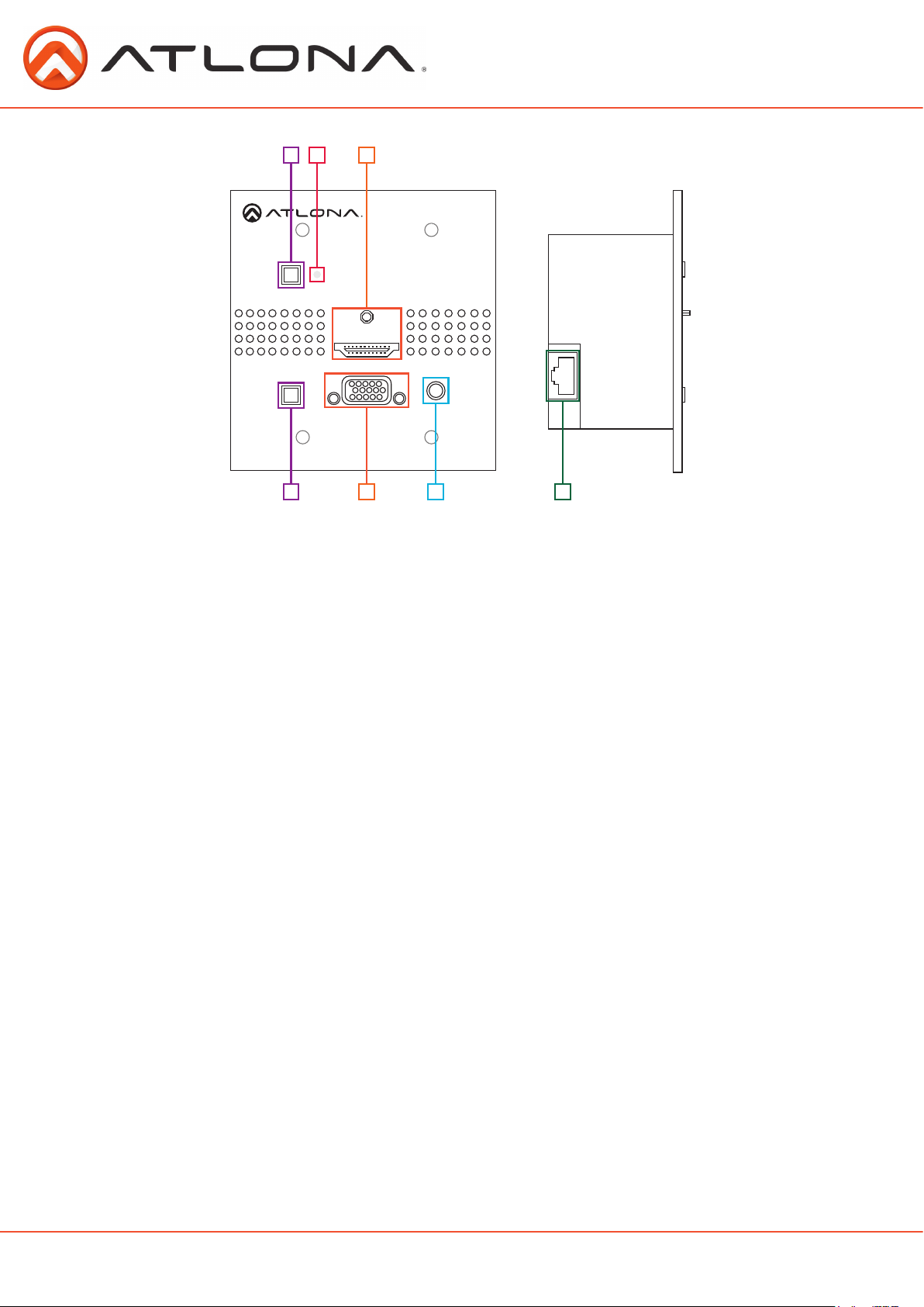
Panel Description
1 2
DISPLAY
ON/OFF
3
LINK
HDMI IN
INPUT
SELECT
VGA IN
AUDIO IN
AT-HDVS-TX-WP
6 764
1. DISPLAY ON/OFF button: Controls display through RS-232 when used with compatible receivers
(Ex. AT-HDVS-RX) - Button will illuminate when the display is off
Note: If DISPLAY ON/OFF button is held for 3 seconds the unit will reset
2. LINK LED: Illuminates when receiving power/signal from compatible receivers (ex. AT-HDVS-RX)
3. HDMI IN: Connect HDMI source here
4. INPUT SELECT button: Use to switch between VGA and HDMI source
Button will illuminate blue for HDMI
Button will illuminate red for VGA
5. VGA IN: Connect VGA source here
6. AUDIO IN: Connect analog audio here (for use with VGA input only)
7. RJ45 port: Connect compatible HDBaseT receiver (ex. AT-HDVS-RX) here
US and UK Face Plate Change
When switching the product between US and UK face plates, three layers of screws will need to be
removed.
First Layer
The first set of screws that need removal are the locking screws for the HDMI and VGA ports. There
are 3 total to remove.
The top white face plate can be removed once those have been taken out.
Second Layer
The second set of screws to remove are in the grey tabs attached to the wall plate back box.
Remove all 4.
The back box can be removed now.
Third Layer
The third set of screws for removal are at the bottom of the PCB boards. Place the grey face plate
down and remove the 4 screws from the corner edges. The grey plate is removable now.
Replace the grey and the white face plates with the correct regional face plate starting at layer 3
until layer one has been replaced.
atlona.com
4
Toll free: 1-877-536-3976
Local: 1-408-962-0515
Page 5

Wall Plate Installation
The HDVS-TX-WP will fit in any 2 Gang (US & UK) electrical box or mud ring (that is at least 40mm
deep).
US
When installing the US version, use the four shorter screws. Thread the screws through the face
plate into the back box (as shown above).
Note: Be sure to plug the CAT cable into the back of the wall plate before full installation
The UK wall plate screws will be the longer than the US screws. Thread the screws through the two
holes in the UK wall plate and into the back box (as shown above).
Note: Be sure to plug the CAT cable into the back of the wall plate before full installation
atlona.com
UK
Toll free: 1-877-536-3976
5
Local: 1-408-962-0515
Page 6

Control Software
Control software and instructions for ease of use can be found on the AT-HDVS-TX-WP webpage
on atlona.com (can only be used with compatible receivers - AT-HDVS-RX)
URL: http://www.atlona.com/HDVS-TX-WP.html (instructions/software found under the “Downloads” tab)
Set Up
RS-232 control is easiest when used with the HDVS-RX receiver.
However when used with appropriate power supply and HDBaseT receiver with RS-232 capabilities,
the display power button can be used to transmit the following commands:
Projector On/Off
WP_Display[a]$cr [a] ? , On , Off Display On/Off control
To change inputs, the HDVS-TX-WP should receive these commands:
WP_Input[a]$cr [a] ? , Hdmi , Vga Select input source (HDVS-TX-WP)
The port settings for the control device are:
115200 bps, 8 bit data length, No parity bit, 1 bit stop-bit, No flow control.
atlona.com
6
Toll free: 1-877-536-3976
Local: 1-408-962-0515
Page 7

Connection and Installation
DISPLAY
ON/OFF
Video
HDBaseT
Audio
LINK
HDMI IN
INPUT
SELECT
CAT5e/6/7 IN FIRMWARE DC 24V
HDMI OUT
VGA IN
+-+
-
L
AUDIO OUT
AUDIO IN
AT-HDVS-TX-WP
-
POWER
LINK
R
RS232
MENU
-
+
+
atlona.com
7
Toll free: 1-877-536-3976
Local: 1-408-962-0515
Page 8

Specifications
Bandwidth 6.75Gbps
Ports
Video input
Video output
Audio input
Firmware update
Power Consumption 17.2W (paired with HDVS-RX)
Audio Passes 2Ch PCM
Resolution Video: up to 1080p
VESA: up to 1920x1200
Distance 230ft @ 1080p over CAT6a/7
197ft @ 1080p over CAT5e/6
Dimensions
Weight
2 Gang (US & UK)
0.73 lbs
0.33 kg
Temperature Operating
32°F to 104°F
0°C to 40°C
Certifications CE, FCC, RoHS, cULus for power supplies
1 x HDMI, 1 x VGA
1 x HDBaseT
1 x Mini USB
1 x 3.5mm
Storage
-4°F to 140°F
20°C to 60°C
atlona.com
8
Toll free: 1-877-536-3976
Local: 1-408-962-0515
Page 9

Safety Information
Safeguards
To reduce the risk of electric shock, do not
expose this product to rain or moisture
If the wall plug does not fit into your local
power socket, hire an electrician to replace
your obsolete socket.
Do not modify the wall plug. Doing so will
void the warranty and safety features.
This equipment should be installed near
the socket outlet and the device should
be easily accessible in the case it requires
disconnection.
Precautions
FCC regulations state that any unauthorized changes or modifications to this equipment, not
expressly approved by the manufacturer, could void the user’s authority to operate this equipment.
Operate this product using only the included external power supply. Use of other power supplies
could impair performance, damage the product, or cause fires.
In the event of an electrostatic discharge this device may automatically turn off. If this occurs,
unplug the device and plug it back in.
Protect and route power cords so they will not be stepped on or pinched by anything placed on or
against them. Be especially careful of plug-ins or cord exit points from this product.
Avoid excessive humidity, sudden temperature changes or temperature extremes.
Keep this product away from wet locations such as bathtubs, sinks, laundries, wet basements, fish
tanks, and swimming pools.
Use only accessories recommended by Atlona to avoid fire, shock, or other hazards.
Unplug the product before cleaning. Use a damp cloth for cleaning and not cleaning fluid or
aerosols. Such products could enter the unit and cause damage, fire, or electric shock. Some
substances may also mar the finish of the product.
Never open, remove unit panels, or make any adjustments not described in this manual. Attempting
to do so could expose you to dangerous electrical shock or other hazards. It may also cause damage
to your AT-HDVS-TX-WP. Opening the product will void the warranty.
Do not attempt to service the unit. Disconnect the product and contact your authorized Atlona
reseller or contact Atlona directly.
atlona.com
9
Toll free: 1-877-536-3976
Local: 1-408-962-0515
Page 10

Warranty
Limited Warranty
Atlona Technologies warrants that (a) its products (AT-HDVS-TX-WP) will perform substantially
in accordance with the accompanying written materials for a period of 3 years from the date of
receipt and (b) that the product will be free from defects in materials and workmanship under
normal use and service for a period of 3 years. In the event applicable law imposes any implied
warranties, the implied warranty period is limited to 3 years from the date of receipt. Some
jurisdictions do not allow such limitations on duration of an implied warranty, so the above
limitation may not apply to customers that fall within those areas.
Customer Remedies
Atlona Technologies’ and its suppliers’ entire liability and Customer’s exclusive remedy shall
be, at Atlona Technologies’ decision, either return of the price paid for the product, repair, or
replacement of the product that does not meet this Limited Warranty and which is returned to
Atlona Technologies with a copy of the Customer’s receipt. This Limited Warranty is void if failure
of the product has resulted from accident, abuse, misapplication, or natural occurrence. In example
but not limited to: power surges (electrical storms, local power outage), dropping the product (or
items on the product), contact with fluids, and physical misconduct (i.e. kicking or punching). Any
replacement product will be warranted for the remainder of the original warranty period.
No other warranties
To the maximum extent permitted by applicable law, Atlona Technologies and its suppliers disclaim
all other warranties, either expressed or implied, including, but not limited to, implied warranties
of merchantability and fitness for a particular purpose, with regard to the product and any related
written materials. This Limited Warranty gives customer specific legal rights. Customers may have
other rights depending on the jurisdiction.
No liability for damages
To the maximum extent permitted by applicable law, in no event shall Atlona Technologies or its
suppliers be liable for any damages arising out of the use of or inability to use this product, even if
Atlona Technologies has been advised of the possibility of such damages. Such damages include
but are not limited to: special, incidental, consequential, or indirect damages for personal injury,
loss of business profits, business interruption, loss of business information, or any other pecuniary
loss. Atlona Technologies’ and its suppliers’ entire liability under any provision of this agreement
shall be limited to the amount actually paid by you for the product. Some Jurisdictions do not allow
the exclusion or limitation of liability for consequential or incidental damage. The above limitations
may not apply to you in such jurisdictional cases.
atlona.com
10
Toll free: 1-877-536-3976
Local: 1-408-962-0515
Page 11

Atlona Product Registration
Thank you for purchasing this Atlona product. - We hope you enjoy it and will take an extra few
moments to register your new purchase.
Registration creates an ownership record if your product is lost or stolen and helps ensure you’ll
receive notification of performance issues and firmware updates.
At Atlona we respect and protect your privacy, assuring you that your registration information is
completely secure. Atlona product registration is completely voluntary and failure to register will not
diminish your limited warranty rights.
To register go to: http://www.atlona.com/registration
atlona.com
11
Toll free: 1-877-536-3976
Local: 1-408-962-0515
 Loading...