

Atlona AT-HDVS-210H-TX-WP Installation Manual
1
Installation Guide
AT-HDVS-210H-TX-WP
Two-Input Wallplate Switcher for HDMI with EthernetEnabled HDBaseT Output
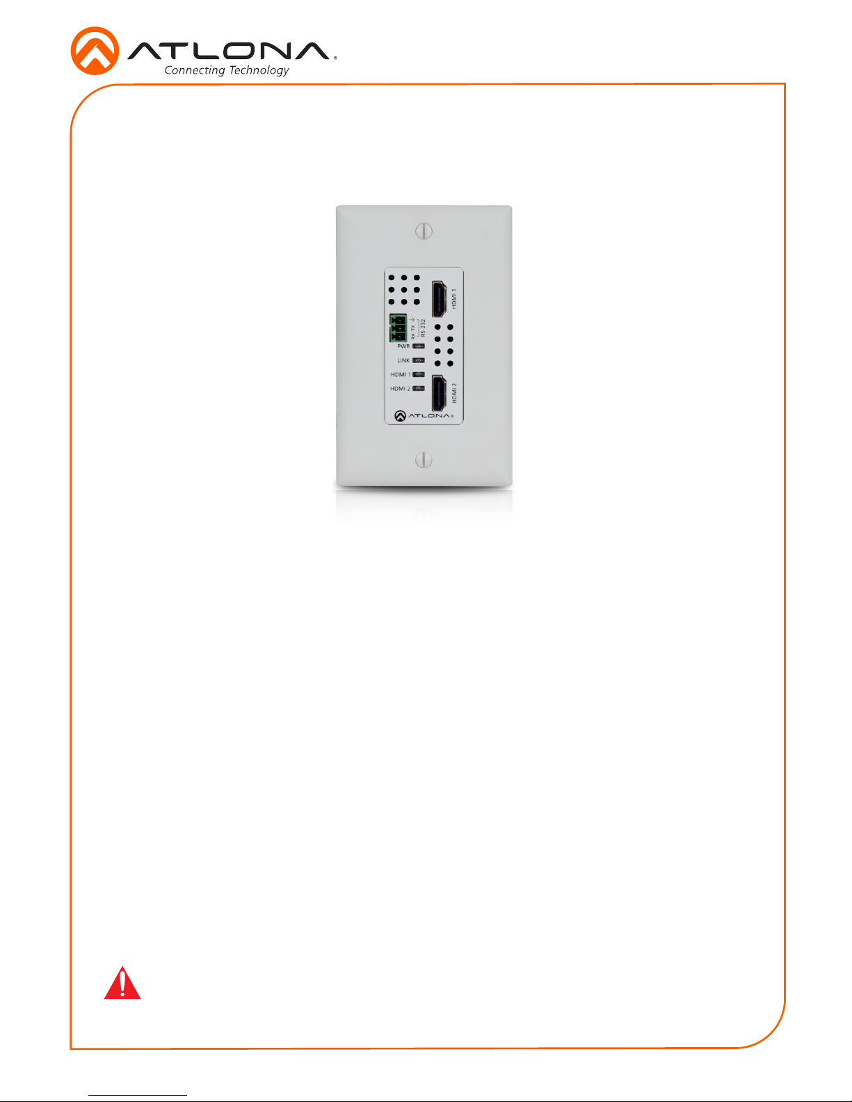
AT-HDVS-210H-TX-WP
The Atlona AT-HDVS-210H-TX-WP is a 2x1 switcher and HDBaseT transmitter with two
HDMI inputs. It features a US one-gang, Decora-style wallplate form factor, and includes
interchangeable black and white wallplates and faceplates. Video signals up to 4K/UHD @ 60
Hz with 4:2:0 chroma subsampling, plus embedded audio and control can be transmitted up to
330 feet (100 meters). The HDVS-210H-TX-WP is HDCP 2.2 compliant. It is designed for use with
select HDVS Series receivers and scalers, as well as the AT-UHD-EX-100CE-RX-PSE receiver,
and Atlona switchers and matrix switchers with HDBaseT inputs. This transmitter can serve as
an integral component of a fully automated AV system, with the convenience of automatic input
selection and display control. It is remotely powered by the AT-UHD-EX-100CE-RX-PSE or other
Atlona HDBaseT-equipped devices through Power over Ethernet (PoE).
IMPORTANT: Visit http://www.atlona.com/product/AT-HDVS-210H-TX-WP for the latest
rmware updates and User Manual.
1 x AT-HDVS-210H-TX-WP
1 x White faceplate with RS-232 cover
1 x White wallplate
1 x Black faceplate with RS-232 cover
1 x Black wallplate
1 x 3-pin captive screw connector
1 x Installation Guide
Package Contents
2
Installation Guide
AT-HDVS-210H-TX-WP
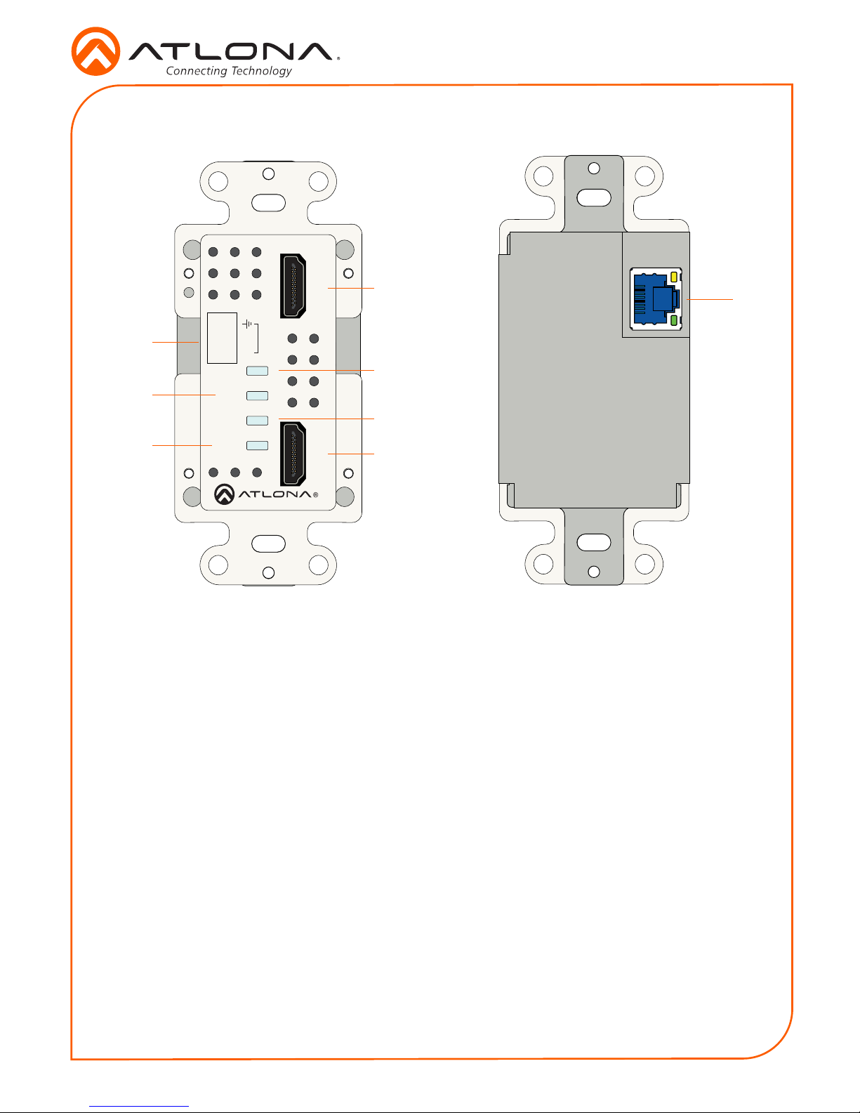
Panel Descriptions
1
8
3
5
2
4
6
7
HDMI 2 HDMI 1
LINK
HDMI 1
HDMI 2
PWR
RS-232
RX TX
AT-HDVS-210H-TX-WP
HDMI
HDBaseT
OUT
1 HDMI 1
Connect an HDMI cable from this port to a UHD/HD source.
2 RS-232
Connect an RS-232 control system to this port. The RS-232 port is covered by a plate and
must be removed to expose the RS-232 port.
3 PWR
This LED indicator glows solid green when the unit is powered.
4 LINK
This LED indicator glows solid green to indicate the presence of an A/V signal.
5 HDMI 1
This LED indicator glows solid green when the HDMI 1 port is the active port.
6 HDMI 2
This LED indicator glows solid green when the HDMI 2 port is the active port.
7 HDMI 2
Connect an HDMI cable from this port to a UHD/HD source.
8 HDBaseT OUT
Connect an Ethernet cable from this port to a locally-powered HDBaseT receiver such as
the AT-HDVS-200-RX or AT-UHD-EX-100CE-RX-PSE.

3
Installation Guide
AT-HDVS-210H-TX-WP
The AT-HDVS-210H-TX-WP provides an RS-232 port which allows communication between a
control system and an RS-232 device. This step is optional.
1. Remove the small plate covering the RS-232 port on the faceplate.
2. Use wire strippers to remove a portion of the RS-232 cable jacket.
3. Remove at least 3/16” (5 mm) from the insulation of the RX, TX, and GND wires.
4. Insert the TX, RX, and GND wires into correct terminal using the included 3-pin captive
screw connector.
5. Connect the opposite end of the cable to the control system.
NOTE: Typical DB9 connectors use pin 2 for TX, pin 3 for RX, and pin 5 for
ground. On some devices functions of pins 2 and 3 are reversed.
RS-232
GND
RX
TX
HDMI 2
LINK
HDMI 1
HDMI 2
PWR
RS-232
RX TX
HDMI1
AT-HDVS-210H-TX-WP
HDMI 2
LINK
HDMI 1
HDMI 2
PWR
RS-232
RX TX
HDMI1
AT-HDVS-210H-TX-WP
small plate
 Loading...