

Atlona AT-HDR-H2H-44M Installation Manual
Installation Guide
1
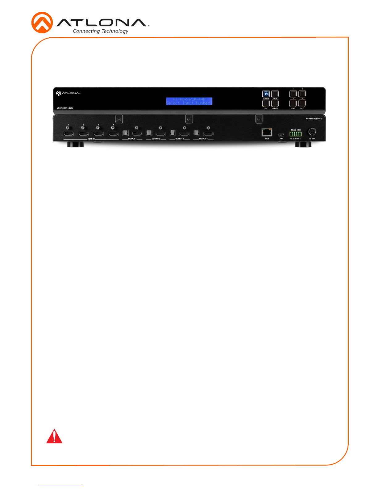
AT-HDR-H2H-44M
4K HDR 4×4 HDMI to HDMI Matrix Switcher
AT-HDR-H2H-44M
1 x AT-HDR-H2H-44M
1 x Captive screw connector, 5-pin
1 x 24V DC power supply
1 x Pair mounting ears w/screws
4 x Feet w/screws
1 x IR remote control
1 x Installation Guide
Package Contents
The Atlona AT-HDR-H2H-44M is a 4×4 HDMI matrix switcher for high dynamic range (HDR)
formats. It is HDCP 2.2 compliant and supports 4K/UHD video @ 60 Hz with 4:4:4 chroma
sampling, as well as HDMI data rates up to 18 Gbps. The HDR-H2H-44M is ideal for residential
applications with the latest as well as emerging 4K/UHD and HDR sources and displays. It
is compatible with all video resolutions, audio formats, and color space formats supported
in the HDMI 2.0b specication, plus the ability to pass metadata for HDR content. The HDR-
H2H-44M includes EDID and HDCP management features, and can send CEC display control
independently to each output. A TOSLINK digital audio output is paired with each HDMI output
for sending de-embedded HDMI audio to an AV receiver or soundbar. The HDR-H2H-44M can be
controlled via Ethernet, RS-232, and IR. A handheld IR remote control is included.
IMPORTANT: Visit http://www.atlona.com/product/AT-HDR-H2H-44M for the latest rm-
ware updates and User Manual.
Installation Guide
2
AT-HDR-H2H-44M
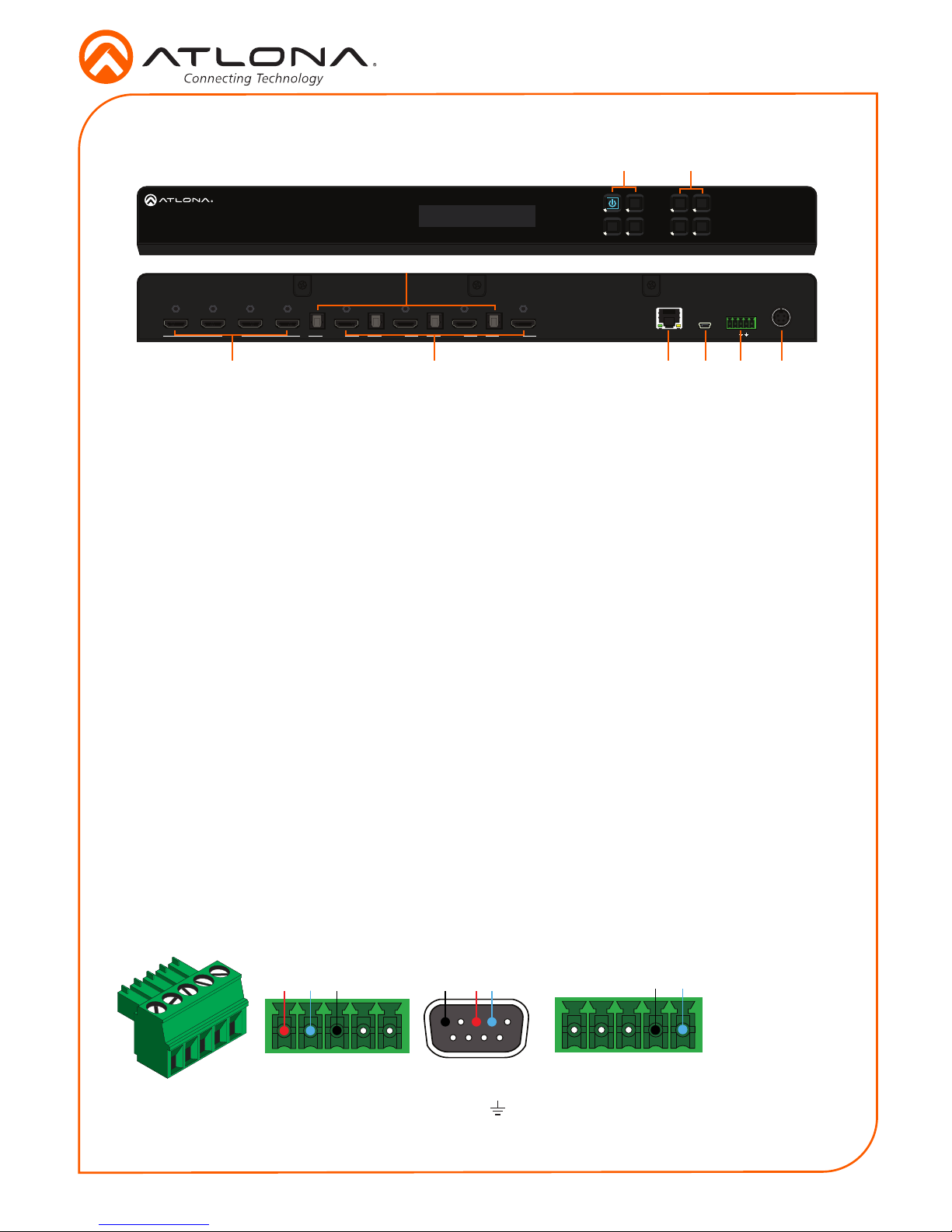
1 Function Buttons
Power - Sets the unit in and out of
standby.
Enter - Used for making selection within
the front panel OSD.
FNC - Use to switch number buttons to
their secondary function.
CANCEL - Navigates back one step in the
front panel OSD.
2 Number Buttons
Use for selection of inputs and outputs.
1 - Press FNC + 1 to route selected input
to all outputs.
2 - Press FNC + 2 to turn the IR receiver
window on and o.
3 - Press FNC + 3 to open the EDID menu.
4 - Press FNC + 4 to display the device
rmware. Press 4 again to view IP, IP port,
and MAC.
3 HDMI IN
Connect HDMI cables to these ports from
HDMI sources.
4 S/PDIF OUT
Connect an optical audio cable from this
TOSLINK port to an audio input device.
5 HDMI OUT
Connect an HDMI cable from this port to
an HDMI display, extender, or switcher.
Only two-channel audio is supported.
6 LAN
Connect an Ethernet cable from this port
to a Local Area Network (LAN). This port
provides access to the webGUI or TCP/
IP control.
7 FW
Connect a mini USB cable to this port to
update the rmware.
8 Control Port
Connect a third party controller or PC
to control the matrix through either IR or
RS-232
9 DC 48V
Connect the included 48V DC power
supply to this power receptacle.
Panel Descriptions
3 5
4
6 7 8 9
AT-HDR-H2H-44M
1 2 3
4
RS-232 IR IN
HDMI IN LAN FW DC 24VSRX TXOUTPUT 1 OUTPUT 2 OUTPUT 3
OUTPUT 4
AT-HDR-H2H-44M
1
2
3
4
POWER
FNC EDID INFO
ENTER
CANCEL
1
2
Pin out will be determined by the
RS-232 cable and connect as
RX (receive), TX (transmit) and
(Ground).
A 5-pin captive screw connector for control has been included. The rst three terminals are RS-
232 control, the last two terminals are for IR.
IR IN is connected by a ground and
signal wire. Use with 3rd party control
systems. For easy termination, Atlona
recommends using the 2 meter IR
cable AT-LC-CS-IR-2M.
Control
RS-232 IR
GND
S
GND RX
TX
GNDRX TX

Installation Guide
3
AT-HDR-H2H-44M
AT-HDR-H2H-44M
1
2 3
4
RS-232IR IN
HDMI IN LAN FW DC 24V
SRXTX
OUTPUT 1
OUTPUT 2
OUTPUT 3
OUTPUT 4
AT-HDR-H2H-44M
1
2
3 4POWER
FNC EDID INFO
ENTER
CANCEL
AT-HDR-H2H-44M
1 2 3
4
RS-232 IR IN
HDMI IN LAN FW DC 24V
SRXTX
OUTPUT 1
OUTPUT 2
OUTPUT 3
OUTPUT 4
AT-HDR-H2H-44M
1
2
3
4
POWER
FNC EDID INFO
ENTER
CANCEL
Mounting Instructions
The AT-HDR-H2H-44M can be mounted in a standard 19-inch rack or placed freestanding on top
of a desk or table.
Rack installation
1. Remove the front two case screws from the sides of the case.
2. Attach the included rack ears to each side of the AT-HDR-H2H-44M using the case screws.
3. Install the HDR-H2H into a rack, using four rack screws.
AT-HDR
NOTE: Increase the air ow as needed to
maintain the recommended temperature
inside the rack.
NOTE: Do not exceed the maximum weight
loads for the rack. Install heaver equipment in
the lower part of the rack for stability.
 Loading...